


ISO/TR 17671-2:2002
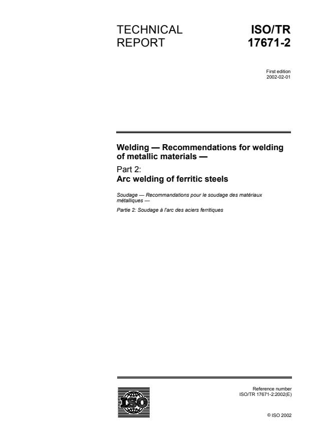
(Main)Welding — Recommendations for welding of metallic materials — Part 2: Arc welding of ferritic steels
Welding — Recommendations for welding of metallic materials — Part 2: Arc welding of ferritic steels
IS/TR 17671-2 gives guidance for manual, semi-mechanized, mechanized and automatic arc welding of ferritic steels, excluding ferritic stainless steels, in all product forms. Details concerning the possible detrimental phenomena which can occur are given with advice on methods by which they can be avoided. This part of ISO/TR 17671 is generally applicable to all ferritic steels and is appropriate regardless of the type of fabrication involved, although the application standard can have additional requirements.
Soudage — Recommandations pour le soudage des matériaux métalliques — Partie 2: Soudage à l'arc des aciers ferritiques
General Information
- Status
- Published
- Publication Date
- 30-Jan-2002
- Technical Committee
- ISO/TC 44/SC 10 - Quality management in the field of welding
- Drafting Committee
- ISO/TC 44/SC 10 - Quality management in the field of welding
- Current Stage
- 9093 - International Standard confirmed
- Start Date
- 25-May-2022
- Completion Date
- 14-Feb-2026
Overview
ISO/TR 17671-2:2002 - Welding - Recommendations for welding of metallic materials - Part 2: Arc welding of ferritic steels - is an informative Technical Report from ISO (TC 44/SC 10) that gives practical guidance for manual, semi‑mechanized, mechanized and automatic arc welding of ferritic steels (excluding ferritic stainless steels) in all product forms. Issued in 2002, this TR supplements general arc‑welding guidance (Part 1) and is intended to help avoid detrimental phenomena and achieve satisfactory weld production and control. Note: as a Technical Report it is informative and may be used alongside application standards that can impose additional requirements.
Key topics and requirements
- Scope and applicability: Guidance applicable to all ferritic steels (groups 1–7 in ISO/TR 15608) and to a wide range of fabrication types.
- Weldability factors: Joint design, hydrogen‑induced (cold) cracking, HAZ toughness and hardness, solidification cracking, lamellar tearing and corrosion.
- Consumables handling: Storage, drying/baking, use of heated quivers or sealed containers to control diffusible hydrogen.
- Joint preparation and weld details: Recommendations for butt and fillet welds, backing, partial penetration, allowable gaps, and preparation of fusion and unwelded faces.
- Preheating and interpass control: Guidance on preheat maintenance temperature and interpass temperatures to control cooling rates and HAZ properties.
- Heat input and cooling time: Consideration of heat input, cooling time (t8/5), and two‑ vs three‑dimensional heat flow for controlling microstructure.
- Welding documentation and control: Advice on welding procedure specification (WPS), inspection and testing, identification, correction of non‑conforming welds and distortion.
- Post‑weld heat treatment (PWHT): Criteria and use to modify HAZ properties where required.
- Annexes: Detailed guidance on avoiding hydrogen cracking (Annex A), joint‑detail design (B), other detrimental phenomena (C), HAZ toughness/hardness (D), solidification cracking (E), and lamellar tearing (F).
Practical applications
ISO/TR 17671-2 is used to:
- Develop and qualify welding procedures (WPS) for ferritic steels.
- Specify preheat, interpass and PWHT regimes to control HAZ hardness/toughness.
- Provide design guidance on joint preparation, backing and fillet weld practice to reduce cracking and distortion.
- Inform QA/QC inspection, consumable handling and remedial actions for non‑conforming welds.
Typical users:
- Welding engineers and procedure writers
- Fabricators and welding supervisors (manual and mechanized processes)
- NDE inspectors, QA/QC managers and materials engineers
- Designers and structural engineers specifying welded steel fabrication
Related standards
Relevant companion documents include:
- ISO/TR 17671‑1 (General guidance for arc welding)
- ISO 9692‑1 (Joint preparation for arc welding)
- ISO 9956‑2 (Welding procedure specification)
- ISO 13916 (Measurement of preheating and interpass temperature)
- ISO/TR 15608 (Material grouping guidelines)
Keywords: ISO/TR 17671-2, arc welding ferritic steels, welding recommendations, hydrogen cracking, heat affected zone, preheating, welding procedure specification, weldability, joint preparation.
Get Certified
Connect with accredited certification bodies for this standard

National Aerospace and Defense Contractors Accreditation Program (NADCAP)
Global cooperative program for special process quality in aerospace.
CARES (UK Certification Authority for Reinforcing Steels)
UK certification for reinforcing steels and construction.
DVS-ZERT GmbH
German welding certification society.
Sponsored listings
Frequently Asked Questions
ISO/TR 17671-2:2002 is a technical report published by the International Organization for Standardization (ISO). Its full title is "Welding — Recommendations for welding of metallic materials — Part 2: Arc welding of ferritic steels". This standard covers: IS/TR 17671-2 gives guidance for manual, semi-mechanized, mechanized and automatic arc welding of ferritic steels, excluding ferritic stainless steels, in all product forms. Details concerning the possible detrimental phenomena which can occur are given with advice on methods by which they can be avoided. This part of ISO/TR 17671 is generally applicable to all ferritic steels and is appropriate regardless of the type of fabrication involved, although the application standard can have additional requirements.
IS/TR 17671-2 gives guidance for manual, semi-mechanized, mechanized and automatic arc welding of ferritic steels, excluding ferritic stainless steels, in all product forms. Details concerning the possible detrimental phenomena which can occur are given with advice on methods by which they can be avoided. This part of ISO/TR 17671 is generally applicable to all ferritic steels and is appropriate regardless of the type of fabrication involved, although the application standard can have additional requirements.
ISO/TR 17671-2:2002 is classified under the following ICS (International Classification for Standards) categories: 25.160.10 - Welding processes. The ICS classification helps identify the subject area and facilitates finding related standards.
ISO/TR 17671-2:2002 is available in PDF format for immediate download after purchase. The document can be added to your cart and obtained through the secure checkout process. Digital delivery ensures instant access to the complete standard document.
Standards Content (Sample)
TECHNICAL ISO/TR
REPORT 17671-2
First edition
2002-02-01
Welding — Recommendations for welding
of metallic materials —
Part 2:
Arc welding of ferritic steels
Soudage — Recommandations pour le soudage des matériaux
métalliques —
Partie 2: Soudage à l'arc des aciers ferritiques
Reference number
©
ISO 2002
PDF disclaimer
This PDF file may contain embedded typefaces. In accordance with Adobe's licensing policy, this file may be printed or viewed but shall not
be edited unless the typefaces which are embedded are licensed to and installed on the computer performing the editing. In downloading this
file, parties accept therein the responsibility of not infringing Adobe's licensing policy. The ISO Central Secretariat accepts no liability in this
area.
Adobe is a trademark of Adobe Systems Incorporated.
Details of the software products used to create this PDF file can be found in the General Info relative to the file; the PDF-creation parameters
were optimized for printing. Every care has been taken to ensure that the file is suitable for use by ISO member bodies. In the unlikely event
that a problem relating to it is found, please inform the Central Secretariat at the address given below.
© ISO 2002
All rights reserved. Unless otherwise specified, no part of this publication may be reproduced or utilized in any form or by any means, electronic
or mechanical, including photocopying and microfilm, without permission in writing from either ISO at the address below or ISO's member body
in the country of the requester.
ISO copyright office
Case postale 56 • CH-1211 Geneva 20
Tel. + 41 22 749 01 11
Fax + 41 22 749 09 47
E-mail copyright@iso.ch
Web www.iso.ch
Printed in Switzerland
ii © ISO 2002 – All rights reserved
Contents Page
Foreword.iv
Introduction.v
1 Scope .1
2 References .1
3 Terms and definitions .1
4 Symbols and abbreviated terms .2
5 Parent metal .3
6 Weldability factors.3
7 Handling of welding consumables .3
8 Weld details.4
9 Welds in holes or slots.4
10 Preparation of joint face.4
11 Alignment of butt welds before welding .5
12 Preheating .5
13 Tack welds.5
14 Temporary attachments.6
15 Heat input .6
16 Welding procedure specification .6
17 Identification .6
18 Inspection and testing.6
19 Correction of non-conforming welds .7
20 Correction of distortion.7
21 Post-weld heat treatment.7
Annex A Avoidance of hydrogen cracking (also known as cold cracking).8
Annex B Guidance on joint detail design (when there is no application standard) .32
Annex C Possible detrimental phenomena resulting from welding of steels, not covered by other
annexes .34
Annex D Heat affected zone toughness and hardness .35
Annex E Avoidance of solidification cracking.42
Annex F Avoidance of lamellar tearing .44
Bibliography.50
Foreword
ISO (the International Organization for Standardization) is a worldwide federation of national standards bodies (ISO
member bodies). The work of preparing International Standards is normally carried out through ISO technical
committees. Each member body interested in a subject for which a technical committee has been established has
the right to be represented on that committee. International organizations, governmental and non-governmental, in
liaison with ISO, also take part in the work. ISO collaborates closely with the International Electrotechnical
Commission (IEC) on all matters of electrotechnical standardization.
International Standards are drafted in accordance with the rules given in the ISO/IEC Directives, Part 3.
The main task of technical committees is to prepare International Standards. Draft International Standards adopted
by the technical committees are circulated to the member bodies for voting. Publication as an International
Standard requires approval by at least 75 % of the member bodies casting a vote.
In exceptional circumstances, when a technical committee has collected data of a different kind from that which is
normally published as an International Standard (“state of the art”, for example), it may decide by a simple majority
vote of its participating members to publish a Technical Report. A Technical Report is entirely informative in nature
and does not have to be reviewed until the data it provides are considered to be no longer valid or useful.
Attention is drawn to the possibility that some of the elements of this part of ISO/TR 17671 may be the subject of
patent rights. ISO shall not be held responsible for identifying any or all such patent rights.
ISO/TR 17671-2 was prepared by Technical Committee ISO/TC 44, Welding and allied processes, Subcommittee
SC 10, Unification of requirements in the field of metal welding.
ISO/TR 17671 consists of the following parts, under the general title Welding — Recommendations for welding of
metallic materials:
Part 1: General guidance for arc welding
Part 2: Arc welding of ferritic steels
Part 3: Arc welding of stainless steels
Part 4: Arc welding of aluminium and aluminium alloys
iv © ISO 2002 – All rights reserved
Introduction
This part of ISO/TR 17671 supplements part 1. It is issued with several annexes in order that it can be extended to
cover the different types of steel which are produced to all the International steel standards for ferritic steels (see
clause 5).
This part of ISO/TR 17671 gives general guidance for the satisfactory production and control of welds in ferritic
steels. Details concerning the possible detrimental phenomena which can occur are given with advice on methods
by which they can be avoided. This part of ISO/TR 17671 is generally applicable to all ferritic steels and is
appropriate regardless of the type of fabrication involved, although the application standard can have additional
requirements.
TECHNICAL REPORT ISO/TR 17671-2:2002(E)
Welding — Recommendations for welding of metallic materials —
Part 2:
Arc welding of ferritic steels
1 Scope
This part of IS/TR 17671 gives guidance for manual, semi-mechanized, mechanized and automatic arc welding of
ferritic steels (see clause 5), excluding ferritic stainless steels, in all product forms.
2 References
ISO 9692-1, Welding and allied processes — Recommendations for joint preparation — Part 1: Manual metal-arc
welding, gas-shielded metal-arc welding and gas welding of steels
ISO 9956-2, Specification and approval of welding procedures for metallic materials — Part 2: Welding procedure
specification for arc welding
ISO 13916, Welding — Guidance on the measurement of preheating temperature, interpass temperature and
preheat maintenance temperature
ISO/TR 15608:2000, Welding — Guidelines for a metallic material grouping system
ISO/TR 17671-1:—, Welding — Recommendations for welding of metallic materials — Part 1: General guidance for
arc welding
3 Terms and definitions
For the purposes of this part of ISO/TR 17671, the terms and definitions given in ISO/TR 17671-1 and the following
apply.
3.1
cooling time
t
8/5
time taken, during cooling, for a weld run and its heat affected zone to pass through the temperature range from
800 °C to 500 °C
3.2
run out length
length of a run produced by the melting of a covered electrode
3.3
run out ratio
R
r
ratio of the run out length to the length of electrode consumed
3.4
shape factor
F
x
influence of the form of a weld on the cooling time, t
8/5
NOTE In the case of two-dimensional heat flow it is called F and in the case of three-dimensional heat flow it is called F .
2 3
3.5
three-dimensional heat flow
heat introduced during welding, which flows parallel and perpendicular to the plate surface
3.6
transition thickness
d
t
plate thickness at which the transition from three-dimensional to two-dimensional heat flow takes place
3.7
two-dimensional heat flow
heat introduced during welding, which flows only parallel to the plate surface
3.8
preheat maintenance temperature
T
m
minimum temperature in the weld zone, which should be maintained if welding is interrupted
4 Symbols and abbreviated terms
4.1 Symbols
See Table 1.
Table 1 — Symbols of the terms used
Symbol Term Unit
.
c Specific heat capacity
J/kg K
d Thickness of plate mm
d
Transition thickness mm
t
D Diameter mm
F
Shape factor for two-dimensional heat flow 1
F
Shape factor for three-dimensional heat flow 1
Q Heat input kJ/mm
R
Run out ratio 1
r
t
Cooling time (from 800 °C to 500 °C) s
8/5
t Melting time of an electrode s
T
Interpass temperature °C
i
T
Preheat maintenance temperature °C
m
T
Initial plate temperature °C
o
T
Preheat temperature °C
p
T
Impact transition temperature °C
t
. .
λ Thermal conductivity
J/cm K s
ρ Density kg/m
2 © ISO 2002 – All rights reserved
4.2 Abbreviations
CE Carbon equivalent (see A.2.1), expressed as a percentage
CET Carbon equivalent (see A.3.2), expressed as a percentage
HAZ Heat affected zone
HD Diffusable hydrogen content in millilitres per 100 g of deposited weld metal
UCS Unit of crack susceptibility
5 Parent metal
This part of ISO/TR applies to ferritic steels excluding ferritic stainless steels. This includes steels referenced in
groups 1 to 7 of ISO/TR 15608:2000. When ordering steel it may be necessary to specify requirements concerning
weldability, which can involve specifying additional requirements to those given in the relevant steel standard.
6 Weldability factors
The properties and the quality of welds are particularly influenced by the welding conditions. Thus, the following
factors should be taken into consideration:
joint design;
hydrogen-induced cracking;
toughness and hardness of the heat affected zone (HAZ);
solidification cracking;
lamellar tearing;
corrosion.
The mechanical and technological properties, in particular the hardness and toughness of the heat affected zone in
a narrowly delineated area, can be influenced to a greater or lesser degree, compared with the properties of the
parent metal and depend on the welding conditions. Experience and tests indicate that, not only the properties of
the narrow affected zone of lower strength and better flexibility, but also the load distribution effect of the tougher
adjacent zones should be taken into account when assessing the ductility and safety against fracture of welded
joints as this could affect the choice of steel.
7 Handling of welding consumables
When special protection or other treatment during storage or immediately prior to use is recommended by the
consumables' manufacturer, these consumables should be treated in accordance with the conditions detailed by
the manufacturer.
When drying or baking, consumables should be removed from their original containers. After removal from the
oven, the consumables should be protected from exposure to conditions conducive to moisture absorption. In the
case of welding consumables that have been specially packaged, e.g. using vacuum or other moisture-resistance
means, advice from the consumables' manufacturer should be sought as to further steps required for drying and
baking.
If controlled hydrogen levels are required, it is recommended that welders be issued with electrodes in heated
quivers or sealed containers.
Drying ovens, e.g. for welding consumables, should be provided with a means of measuring the oven temperature.
8 Weld details
8.1 Butt welds
Butt joints between parts of unequal cross-section should be made and subsequently shaped such that a severe
stress concentration at the junction is avoided.
Some examples of joint preparations for use with metal-arc welding with covered electrodes and gas-shielded
metal-arc welding are given in ISO 9692-1.
Partial penetration butt joints may be permitted dependant on the design specification. Consideration should be
given to the choice of weld preparation and welding consumables in order to achieve the specified throat thickness.
Under fatigue conditions, partial penetration joints or the use of permanent backing material may be undesirable.
Backing material may consist of another steel part of the structure when this is appropriate. When it is not
appropriate to use part of the structure as backing material, the material to be used should be such that detrimental
effects on the structure are avoided and should also be agreed in the design specification.
Care should be taken when using copper as a backing material as there is a risk of copper pick-up in the weld
metal.
Where temporary or permanent backing material is used, the joint should be arranged in such a way as to ensure
that complete fusion of the parts to be joined is readily achieved.
Wherever the fabrication sequence allows, tack welds, attaching permanent backing should be positioned for
subsequent incorporation into the weld (see clause 14 of ISO/TR 17671-1:—).
8.2 Fillet welds
Unless otherwise specified, the edges and surfaces to be joined by fillet welding should be in as close contact as
possible since any gap may increase the risk of cracking. Unless otherwise specified, the gap should not exceed
3 mm. Consideration should be given to the need to increase the throat of the fillet weld to compensate for a large
gap.
Unless otherwise specified, welding should not start/stop near corners, instead, it should be continued around the
corners.
9 Welds in holes or slots
Due to the risk of cracking, holes or slots should not be filled with weld metal unless required by the design
specification. Holes or slots that are required to be filled with weld metal shall only be filled after the first run has
been found to be acceptable (see also B.4).
10 Preparation of joint face
10.1 General
Any large notches or any other errors in joint geometry which might occur should be corrected by applying a weld
deposit according to an approved welding procedure. Subsequently, they should be ground smooth and flush with
the adjacent surface to produce an acceptable finish.
Prefabrication primers (shop primers) may be left on the joint faces provided that it is demonstrated that they do not
adversely affect the welding.
4 © ISO 2002 – All rights reserved
10.2 Fusion faces
When shearing is used, the effect of work hardening should be taken into account and precautions should be taken
to ensure that there is no cracking of the edges.
Single- and double-U and single-J weld preparations usually have to be machined. In assessing the methods of
preparation and type of joint, the requirements of the chosen welding process should be taken into account.
10.3 Unwelded faces
Where a cut edge is not a fusion face, the effect of embrittlement from shearing, thermal cutting or gouging should
not be such as to adversely affect the workpiece.
Local hardening can be reduced by suitable thermal treatment or removed by mechanical treatment. The removal
of 1 mm to 2 mm from a cut face normally eliminates the hardened layer. When using thermal cutting, local
hardening can be lessened by a reduction in usual cutting speed or by preheating before cutting. If necessary the
steel supplier should be consulted for recommendations on achieving a reduction in hardness.
U and J weld preparations as compared with V and bevel weld preparations serve to reduce distortion by virtue of
the smaller amount of weld metal required. Likewise, double preparations are better than single preparations in that
the weld metal can be deposited in alternate runs on each side of the joint. In the control of distortion, accuracy of
preparation and fit-up of parts are important considerations, as well as a carefully planned and controlled welding
procedure.
11 Alignment of butt welds before welding
Unless specified otherwise (e.g. in a welding procedure specification or an application standard), the root edges or
root faces of butt joints should not be out of alignment by more than 25 % of the thickness of the thinner material,
for material up to and including 12 mm thick, or by more than 3 mm for material thicker than 12 mm.
For certain applications and welding processes, closer tolerances may be necessary.
NOTE An application standard means a relevant product standard.
12 Pre-heating
The points of temperature measurement should be in accordance with ISO 13916 except that for all thicknesses
the distance for measurement should be at least 75 mm from the weld centre line.
Particular attention should be paid to the need for pre-heating when making low heat input welds, e.g. tack welds.
13 Tack welds
It is recommended that the minimum length of a tack weld be 50 mm, but for material thicknesses less than 12 mm
the minimum length of a tack weld should be four times the thicker part. For materials of thickness greater than
50 mm or of yield strength over 500 N/mm consideration should be given to increasing the length and size of tack
welds, which may involve the use of a two-run technique. Consideration should also be given to the use of lower
strength and/or higher ductility consumables when welding higher alloy steel.
14 Temporary attachments
If a thermal process is used to remove a temporary attachment or run on/off pieces after welding, sufficient
attachment or run on/off pieces should be left to allow subsequent removal of the heat-affected material by careful
grinding.
15 Heat input
Heat input is calculated from the weld travel speed (see clause 19 of ISO/TR 17671-1:—). When weaving with
manual metal-arc welding, the weave width should be restricted to three times the diameter of the core rod.
NOTE This limitation of weave width refers only to the calculation of the heat input.
For multi-wire arc welding, the heat input is calculated as the sum of the heat input for each individual wire using
the individual current and voltage parameters.
16 Welding procedure specification
The welding procedure specification should comply with ISO 9956-2 and include the following:
a) whether shop or site welding;
b) maximum combined thickness (see A.2.4) if annex A.2 is applied; plate thickness if annex A.3 is applied;
c) heat input (see clause 15);
d) hydrogen scale (see A.2.3 and A.3.2);
e) tack welds (see clause 13).
17 Identification
Where the use of hard stamp marks is required by the contract, guidance on their location and size should be
given. Indentations used for marking in radiographic examination require equal consideration.
18 Inspection and testing
Due to the risk of delayed cracking, a period of at least 16 h is generally required before the final inspection is
made of as-welded fabrications. The minimum time may be reduced for thin materials below 500 N/mm yield
strength or increased for materials of thickness greater than 50 mm or of yield strength over 500 N/mm . Whatever
period is used it should be stated in the inspection records.
Welds that have been heat-treated to reduce the hydrogen content or which have been stress relieved, need no
additional time interval following the heat treatment before final inspection is made.
Tungsten inert gas welding (TIG) and other remelting processes, if required for post-weld treatment, should be
performed before final inspection.
Welds which are to be inspected and approved should not be painted or otherwise treated until they have been
accepted.
6 © ISO 2002 – All rights reserved
19 Correction of non-conforming welds
All welds which do not conform to the design specification should be corrected.
NOTE Fracture mechanics or other assessment techniques may be used to determine whether a non-conforming weld
needs to be corrected.
20 Correction of distortion
The temperature of heated areas, measured by appropriate methods, should be in accordance with the
recommendations of the material supplier or the design specification.
21 Post-weld heat treatment
When post-weld heat treatment of welds is required but no application standard exists, the heat treatment details
should be stated in the design specification taking account of the effect on the properties of the parent metal, HAZ
and weld metal.
Annex A
Avoidance of hydrogen cracking (also known as cold cracking)
A.1 General
This annex gives recommendations for the avoidance of hydrogen cracking.
In preparing this annex, full account was taken of the fact that many methods have been proposed for predicting
preheat temperatures to avoid hydrogen cracking in non-alloyed, fine grained and low alloy steel weldments.
Examples are given in IIW documents IX-1602-90 and IX-1631-91. Two methods are included in this annex as A.2
and A.3. Method A given in A.2 is based on extensive experience and data which is mainly, but not exclusively, for
carbon manganese type steels. Method B given in A.3 is based on experience and data which is mainly, but not
exclusively, for low alloy, high strength steels. The differences in origin and experience used to develop these two
methods can be used as a guide as to their application.
The method described under A.4 is used for creep resistant and low temperature steels.
The recommendations apply only to normal fabrication restraint conditions. Higher restraint situations may need
higher preheat temperatures or other precautions in order to prevent hydrogen cracking.
Clauses A.2 and A.3 refer to welding of parent metal at temperatures above 0 °C. When welding is carried out
below this temperature it is possible that special requirements will be needed.
Alternative procedures to those derived from this annex may be used, e.g. lower preheat temperatures, provided
they are supported by evidence of their effectiveness. The evidence should include all the factors also considered
for the welding procedures as given in this annex.
A.2 Method A for the avoidance of hydrogen cracking in non-alloyed, fine grained and
low alloy steels
A.2.1 Parent metal
Clause A.2 covers non-alloyed, fine grained and low alloy steels.
The range of chemical composition in percentage by weight of the main alloy constituents is:
carbon 0,05 to 0,25
silicon 0,8 max.
manganese 1,7 max.
chromium 0,9 max.
copper 1,0 max.
nickel 2,5 max.
molybdenum 0,75 max.
vanadium 0,20 max.
8 © ISO 2002 – All rights reserved
The determination of safe, but economic, preheating levels for the prevention of hydrogen cracking is critically
dependent on an accurate knowledge of parent metal composition and carbon equivalent, CE, and on the weld
metal composition (see A.2.9).
CE values for parent material are calculated using the following formula:
Mn Cr++Mo V Ni+ Cu
CE=+C + + in % (A.1)
65 15
Clause A.2 is applicable to steels with a CE in the range 0,30 to 0,70.
If, of the elements in this formula, only carbon and manganese are stated on the mill sheet for carbon and carbon
manganese steels, then 0,03 should be added to the calculated value in order to allow for residual elements.
Where steels of different CE or grade are being joined, the higher CE value should be used.
This CE formula may not be suitable for boron-containing steels.
A.2.2 Factors affecting cracking
The occurrence of hydrogen cracking depends on a number of factors; composition of the steel, the welding
procedure, welding consumables and the stress involved. If the t time associated with welding is too short,
8/5
excessive hardening can occur in the HAZ. When the hydrogen in the weld is above a critical level the hardened
zone can crack spontaneously under the influence of residual stress after the weld has cooled to near ambient
temperature. Welding conditions may be selected to avoid cracking by ensuring that the HAZ cools sufficiently
slowly, by control of weld run dimensions in relation to metal thickness, and if necessary, by applying preheat and
controlling interpass temperature. Procedures for avoiding hydrogen cracking, as well as selecting cooling times
through the transformation temperature range to avoid hardened and susceptible microstructures, may involve
controlling cooling in the lower temperature part of the thermal cycle, typically from 300 °C to 100 °C, thereby
beneficially influencing the evolution of hydrogen from the welded joint. In particular, this can be achieved by the
application of a post heat on completion of welding simply by maintaining the preheat temperature.
The hydrogen content of the weld can be controlled by using hydrogen controlled welding processes and
consumables, and also to some extent, by the application of post-heat as described above.
Similar considerations apply to hydrogen cracking in the weld metal where, although hardening will be on a
reduced scale, actual hydrogen and stress levels are likely to be higher than in the heat affected zone. In general,
welding procedures selected to avoid HAZ hydrogen cracking will also avoid cracking in the weld metal. However,
under some conditions such as high restraint, low CE steels, thick sections or alloyed weld metal, weld metal
hydrogen cracking can become the dominant mechanism.
The most effective assurance of avoiding hydrogen cracking is to reduce the hydrogen input to the weld metal from
the welding consumables. The benefits resulting from a growing number of possibilities where no preheat
temperature > 20 °C is required, can — as shown by examples in Table A.1 — be increased by using filler
materials with lower hydrogen content.
Welding conditions for avoiding hydrogen cracking in carbon manganese steels have been drawn up in graphical
form in Figure A.2 for the normal range of compositions, expressed as CE, covered by this part of ISO/TR 17671
and these conditions should be followed for all types of joint whenever practicable.
The conditions have been drawn up to take account of differences in behaviour between different steels of the
same CE (making allowances for scatter in hardness) and of normal variations between ladle and product analysis.
They are valid for the avoidance of both HAZ and weld metal cracking in the majority of welding situations (see also
A.2.9).
Table A.1 — Examples of maximum combined thickness (see A.2.4) weldable without preheat
a
Maximum combined thickness
HD
CE of 0,49 CE of 0,43
ml/100 g of deposited
Heat input Heat input
metal
1,0 kJ/mm 2,0 kJ/mm 1,0 kJ/mm 2,0 kJ/mm
mm mm mm mm
> 15 25 50 40 80
10 u 15 30 55 50 90
5 u 10 35 65 60 100
3 u 5 50 100 100 100
3 60 100 100 100
u
a
Measured in accordance with ISO 3690.
A.2.3 Hydrogen content of welding consumables
A.2.3.1 General
The manufacturer should be able to demonstrate that he has used the consumables in the manner recommended
by the consumables' manufacturer and that the consumables have been stored and dried or baked to the
appropriate temperature levels and times.
A.2.3.2 Hydrogen scales
The hydrogen scale to be used for any arc welding process depends principally on the weld diffusable hydrogen
content, HD, and should be as given in Table A.2. The value used should be stated by the consumables'
manufacturer in accordance with the relevant standard where it exists (or as independently determined) in
conjunction with a specified condition of supply and treatment.
Table A.2 — Hydrogen scales
HD
Hydrogen scale
ml/100 g of deposited metal
15 A
>
10 u 15 B
5 u 10 C
3 5 D
u
u 3 E
10 © ISO 2002 – All rights reserved
A.2.3.3 Selection of hydrogen scales
The following gives general guidance on the selection of the appropriate hydrogen scale for various welding
processes.
Manual metal-arc basic covered electrodes can be used with scales B to D depending on the electrode
manufacturer's classification of the consumable. Manual metal-arc rutile or cellulosic electrodes should be used
with scale A.
Flux-cored or metal-cored consumables can be used with scales B to D depending on the manufacturer's
classification of the wire. Submerged arc wire and flux consumable combinations can have hydrogen levels
corresponding to scales B to D, although most typically these will be scale C but therefore need assessing in the
case of each named product combination and condition. Submerged arc fluxes can be classified by the
manufacturer but this does not necessarily confirm that a practical flux/wire combination also meets the same
classification.
Solid wires for gas-shielded arc welding and for TIG welding may be used with scale D unless specifically assessed
and shown to meet scale E. Scale E may also be found to be appropriate for some cored wires and some manual
metal-arc basic covered electrodes, but only after specific assessment. On achieving these low levels of hydrogen,
consideration should be given to the contribution of hydrogen from the shielding gas composition and atmospheric
humidity from welding.
For plasma arc welding, specific assessment should be made.
A.2.4 Combined thickness
Combined thickness should be determined as the sum of the parent metal thicknesses averaged over a distance of
75 mm from the weld line (see Figure A.1).
Combined thickness is used to assess the heat sink of a joint for the purpose of determining the cooling rate.
If the thickness increases greatly just beyond 75 mm from the weld line, it may be necessary to use a higher
combined thickness value.
For the same metal thickness, the preheating temperature is higher in a fillet weld than in a butt weld because the
combined thickness, and therefore the heat sink, is greater.
A.2.5 Preheat temperature
The preheating temperature to be used should be obtained from Figure A.2 a) to m) by reading the preheat line
immediately above or to the left of the co-ordinated point for heat input and combined thickness.
A.2.6 Interpass temperature
The minimum recommended interpass temperature is frequently used as the preheat temperature for multi-run
welds. However, multi-run welds may have a lower permitted interpass temperature than the preheat temperature
where subsequent runs are of higher heat input than the root run. In these cases the interpass temperature should
be determined from Figure A.2 a) to m) for the larger run. Recommendations relating to maximum interpass
temperature for creep resisting and low temperature steels are given in Table A.5 and Table A.6.
A.2.7 Heat input
Heat input values (in kJ/mm) for use with Figure A.2 should be calculated in accordance with ISO/TR 17671-1 and
clause 15.
Dimensions in millimetres
NOTE The limited heat sink should be considered (see A.2.10b).
a
d = average thickness over a length of 75 mm.
b
For simultaneously deposited directly opposed twin fillet welds, combined thickness = ½ (d + d + d ).
1 2 3
c
Combined thickness = d + d + d .
1 2 3
d
Combined thickness = ½ (D + D ); maximum diameter = 40 mm.
1 2
Figure A.1 — Examples for the determination of combined thickness
A.2.8 Hydrogen reduction by post-heating
When there is a higher risk of cold cracking, hydrogen release should be accelerated by either maintaining the
minimum interpass temperature or raising the temperature to between 200 °C and 300 °C immediately after
welding and before the weld region cools to below the minimum interpass temperature. The duration of post-
heating should be at least 2 h and is a function of the thickness. Large thicknesses require temperatures at the
upper end of the stated range as well as prolonged post-heating times.
Post-heating is also appropriate where a partially filled weld cross-section is to be cooled.
A.2.9 Conditions which may require more stringent procedures
The preheating conditions presented in Figure A.2 have been found from experience to provide a satisfactory basis
for deriving safe welding procedures for many welded fabrications. However, the risk of hydrogen cracking is
influenced by several parameters and these can sometimes exert an adverse influence greater than accounted for
in Figure A.2 a) to m). The following paragraphs cover some factors which can increase the risk of cracking above
that envisaged in drawing up the data in Figure A.2. Precise quantification of the effects of these factors on the
need for a more stringent procedure and on the change to the welding procedure required to avoid cracking cannot
currently be made. The following factors should therefore be considered for guidance only.
12 © ISO 2002 – All rights reserved
Joint restraint is a complex function of section thickness, weld preparation, joint geometry and the stiffness of the
fabrication. Welds made in section thicknesses above approximately 50 mm and root runs in double bevel butt
joints may require more stringent procedures.
Certain welding procedures may not be adequate for avoiding weld metal hydrogen cracking when welding steels
of low CE. This is more likely to be the case when welding thick sections (i.e. greater than about 50 mm) and with
higher heat inputs.
The use of higher strength alloyed weld metal or carbon manganese weld metal with a manganese content above
approximately 1,5 % can lead to higher operating stresses. Whether or not this causes an increased risk of HAZ
cracking, the weld deposit would generally be harder and more susceptible to cracking itself.
Experience and research has indicated that lowering the inclusion content of the steel, principally by lowering the
sulfur content (but also the oxygen content) can increase the hardenability of the steel. From a practical point of
view, this effect can result in an increase in the hardness of the HAZ, and possibly a small increase in the risk of
HAZ hydrogen cracking. Accurate quantification of the effect is currently not practicable.
Although modifications to the procedures for dealing with welds involving the above factors can, in principle, be
obtained through a change in heat input, preheating or other influencing factors, the most effective modification is
to lower the weld hydrogen level. This can be done either directly, by lowering the weld hydrogen input to the weld
(use of lower hydrogen welding processes or consumables), or by increasing hydrogen loss from the weld by
diffusion through the use of higher post-heat for a period of time after welding. The required post-heat time will
depend on many factors, but a period of 2 h to 3 h has been found to be beneficial in many instances. It is
recommended that the required modifications to the procedures be derived by the use of adequate joint simulation
weld testing.
A.2.10 Relaxations
Relaxations of the welding procedures may be permissible under the following conditions.
a) General preheating
If the whole component or a width more than twice that stated in clause 12 is preheated, it is generally possible
to reduce the preheating temperature by a limited amount.
b) Limited heat sink
If the heat sink is limited in one or more directions (e.g. when the shortest heat path is less than × 10 the fillet
leg length) especially in the thicker plate (e.g. in the case of a lap joint where the outstand is only marginally
greater than the fillet weld leg length), it is possible to reduce preheating levels.
c) Austenitic consumables
In some circumstances where sufficient preheating to ensure crack-free welds is impracticable an advantage
can be gained by using certain austenitic or high nickel alloy consumables. In such cases preheat is not
always necessary, especially if the condition of the consumable is such as to deposit weld metal containing
very low levels of hydrogen.
d) Joint fit up
Close fit fillet welds (where the gap is 0,5 mm or less) may justify relaxations in the welding procedure.
A.2.11 Simplified conditions for manual metal-arc welding
Where single run minimum leg length fillet welds are specified in the design, Table A.3 can be used to determine
the approximate heat input values for use in determining preheat temperatures from Figure A.2.
These values are appropriate for practical situations when a manufacturer is required to make single run fillet welds
of specified dimensions related to the minimum leg length of the fillet welds. In practice, one leg will be longer than
the minimum, as, e.g., in a horizontal-vertical fillet weld and the data are therefore not appropriate for direct
conversion to welds of specified throat dimension.
In other cases heat input should be controlled by control of electrode run out length (see Table A.4) or directly
through welding parameters.
Table A.3 — Values of heat input for manual metal-arc welding of single run fillet welds
a
Heat input for electrodes with different covering types
and electrode efficiencies
Minimum leg length
mm R and RR < 110 % B < 130 % R and RR > 130 %
kJ/mm kJ/mm kJ/mm
4 0,8 1,0 —
5 1,1 1,4 0,6
6 1,6 1,8 0,9
8 2,2 2,7 1,3
a
Covering types in accordance with ISO 2560.
Scale A B C D E Scale A B C D E
To be used for carbon To be used for carbon
equivalent not 0,30 0,34 0,38 0,44 0,46 equivalent not 0,34 0,39 0,41 0,46 0,48
exceeding exceeding
a) b)
Figure A.2 — Conditions for welding steels with defined carbon equivalents
14 © ISO 2002 – All rights reserved
Scale A B C D E Scale A B C D E
To be used for carbon To be used for carbon
0,38 0,41 0,43 0,48 0,50 0,41 0,43 0,45 0,50 0,52
equivalent not equivalent not
exceeding exceeding
c) d)
Scale A B C D E
To be used for carbon
0,43 0,45 0,47 0,53 0,55
equivalent not exceeding
e)
Figure A.2 — Conditions for welding steels with defined carbon equivalents
Scale A B C D E
To be used for carbon
0,45 0,47 0,49 0,55 0,57
equivalent not exceeding
f)
Scale A B C D E
To be used for carbon
0,47 0,49 0,51 0,58 0,60
equivalent not exceeding
g)
Figure A.2 — Conditions for welding steels with defined carbon equivalents
16 © ISO 2002 – All rights reserved
Scale A B C D E
To be used for carbon
0,49 0,51 0,53 0,60 0,62
equivalent not exceeding
h)
Scale A B C D E
To be used for carbon
0,51 0,53 0,55 0,62 0,64
equivalent not exceeding
i)
Figure A.2 — Conditions for welding steels with defined carbon equivalents
Scale A B C D E
To be used for carbon
0,53 0,55 0,57 0,64 0,66
equivalent not exceeding
j)
Scale A B C D E
To be used for carbon
0,55 0,57 0,59 0,66 0,68
equivalent not exceeding
k)
Figure A.2 — Conditions for welding steels with defined carbon equivalents
18 © ISO 2002 – All rights reserved
Scale A B C D E
To be used for carbon
— — 0,60 0,68 0,70
equivalent not exceeding
l)
Scale A B C D E
To be used for carbon
— — 0,62 0,70 —
equivalent not exceeding
m)
Figure A.2 — Conditions for welding steels with defined carbon equivalents
Table A.4 — Run out length for manual metal-arc welding
Table A.4.1 — Electrode efficiency 95 % approximately
Run out length from 410 mm
...
Questions, Comments and Discussion
Ask us and Technical Secretary will try to provide an answer. You can facilitate discussion about the standard in here.
Loading comments...