

ISO 5149-2:2026
(Main)Refrigerating systems and heat pumps — Safety and environmental requirements — Part 2: Design, construction, testing, marking and documentation
- Abstract
This document specifies the design, construction and installation of refrigerating systems, including piping, components, materials and ancillary equipment directly associated with such systems, which are not covered in ISO 5149-1, ISO 5149-3, or ISO 5149-4. It also specifies requirements for testing, commissioning, marking and documentation. Requirements for secondary heat-transfer circuits are excluded except for any safety devices associated with the refrigerating system. This document is applicable to new refrigerating systems, extensions or modifications of already existing systems, and for used systems, being transferred to and operated on another site. This document is applicable to: refrigerating systems, stationary or mobile, of all sizes, except vehicle air conditioning systems covered by a specific product standard; NOTE Example of specific product standard is ISO 13043 and SAE J 639. secondary cooling or heating systems; the location of the refrigerating systems; replaced parts and added components after the adoption of this document, if they are not identical in function and in capacity; the conversion of a system for another refrigerant. This document does not apply to goods in storage, with respect to spoilage or contamination.
- Status
- Published
- Publication Date
- 04-Nov-2026
- Current Stage
- 6060 - International Standard published
- Start Date
- 05-Nov-2026
- Completion Date
- 05-Nov-2026
ISO 5149-2:2026 is an International Standard from ISO for the design, construction, testing, marking and documentation of refrigerating systems and heat pumps. It sets safety and environmental requirements for the system itself, including piping, components, materials and ancillary equipment, and it is written for designers, manufacturers, installers, and people who commission or inspect these systems.
What does ISO 5149-2:2026 specify?
ISO 5149-2:2026 specifies how refrigerating systems and directly associated equipment are designed, built, installed, tested, marked and documented. It applies to new systems, extensions, modifications, used systems moved to another site, and systems converted for another refrigerant.
The scope covers stationary and mobile refrigerating systems of all sizes, secondary cooling or heating systems, the installation location, and replaced or added parts when they are not identical in function and capacity. It excludes secondary heat-transfer circuits except for safety devices associated with the refrigerating system, and it does not apply to goods in storage with respect to spoilage or contamination.
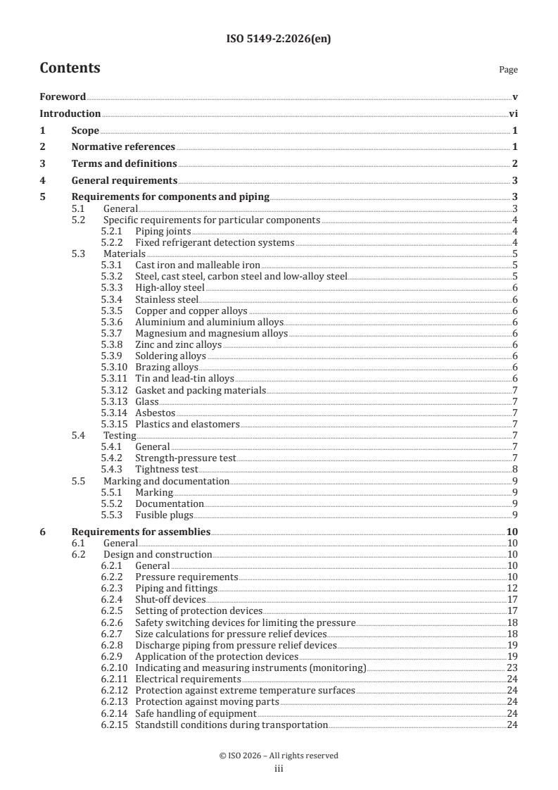
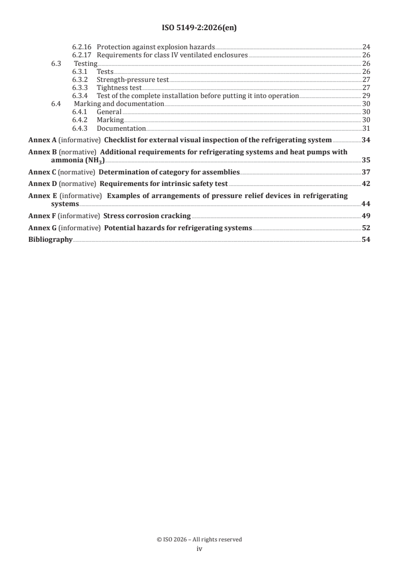
The document is organized into six clauses and seven annexes.
| Annex | What it covers |
|---|---|
| Annex A | Checklist for external visual inspection of the refrigerating system |
| Annex B | Additional requirements for refrigerating systems and heat pumps with ammonia (NH3) |
| Annex C | Determination of category for assemblies |
| Annex D | Requirements for intrinsic safety test |
| Annex E | Examples of arrangements of pressure relief devices in refrigerating systems |
| Annex F | Stress corrosion cracking |
| Annex G | Potential hazards for refrigerating systems |
What are the key requirements of ISO 5149-2:2026?
ISO 5149-2:2026 focuses on preventing hazards to people, property and the environment through design choices, component selection, testing and documentation. In practice, it tells the designer what to check, what to protect, and what to record before a system goes into service.
General safety intent and relation to product standards
Clause 4 requires refrigerating systems and components to be designed and constructed to eliminate possible hazards. Deliberate refrigerant discharge is only allowed in a way that is not harmful, so leak management and venting need to be planned, not improvised.
Clause 4 also recognizes conformity pathways through certain product standards. For equipment built to those standards, the practical point is to check which parts of ISO 5149-2 still apply, especially mechanical strength and pressure safety where IEC 60335-2-40 is involved.
Components, piping and materials
Clause 5 ties each component or piping item to the standard or requirement that applies to it. Table 1 is central here because it links items such as detectors, heat exchangers, compressors, valves, flexible piping, safety devices and gauges to either a related product standard or to the detailed requirements in Clauses 5.2 to 5.5.
Clause 5 also covers materials. The practical effect is that the material choice is not just a design preference - it has to suit the refrigerant, pressure, temperature and corrosion conditions, with special attention to combinations that can lead to stress corrosion cracking.
Testing, tightness and marking of components
Clause 5 requires strength-pressure testing and tightness testing for components and piping, together with marking and documentation. The important point for manufacturers is that the part must not only work in service, it must also be shown to be sound before it is put into the system.
Clause 5.5 also covers fusible plugs. That matters because pressure-protection elements need to be identified and documented like other safety-related parts.
Assembly design and pressure protection
Clause 6 is the core part for complete refrigerating system assemblies. It requires the whole assembly to be designed, constructed, tested, installed, documented and marked in accordance with Clause 6, and it adds special requirements for assemblies using ammonia in Annex B.
Pressure design is a major theme in Clause 6.2. The standard covers maximum allowable pressure, component pressure limits, damage limitation in external fire, piping and fittings, shut-off devices, protection-device settings, pressure-relief sizing, discharge piping and the application of protection devices. For the reader, this means the pressure path of the system must be planned as a complete chain, not as isolated parts.
Monitoring, electrical safety and hazards
Clause 6.2 also covers indicating and measuring instruments, electrical requirements, protection against hot or cold surfaces, moving parts, handling, transport standstill conditions, explosion hazards, and class IV ventilated enclosures. These requirements matter because refrigerating systems can create both mechanical and electrical risks in normal operation and during abnormal events.
Testing before putting the installation into operation
Clause 6.3 requires testing of the complete installation before operation. It includes inspection of the refrigerating system, verification of safety devices, refrigerant piping checks and visual inspection of the complete installation. The practical message is that commissioning is not just a functional run - the system has to be checked as a complete safety-relevant installation.
Marking and documentation for the assembly
Clause 6.4 requires marking and documentation for the finished system. This covers certificates, documentation at the operating site, the instruction manual, drawings and the logbook. In practice, the standard expects the system to be handed over with the information needed for safe use, maintenance and later changes.
Ammonia, categorization and intrinsic safety
Annex B adds extra requirements for refrigerating systems and heat pumps with ammonia (NH3), including shut-off devices, emergency stop arrangements and oil drain provisions for certain ammonia systems. Annex C gives the method for determining the category of an assembly, using refrigerant safety classification, pressure, refrigerant state and component category. Annex D gives the requirements for the intrinsic safety test when the decision path in Clause 6.2.9.2 leads to that option.
What terms does ISO 5149-2:2026 define?
Clause 3 adopts the definitions and abbreviations in ISO 5149-1, so the vocabulary is shared across the ISO 5149 series. These are some of the key terms and abbreviations used in this part:
- PS - maximum allowable pressure used as a key design basis for the refrigerating system assembly.
- HSIT - hot surface ignition temperature, introduced in this edition as a safety-related concept for ignition assessment.
- NH3 - ammonia, the refrigerant covered by the additional requirements in Annex B.
- GHS - Globally Harmonized System of Classification and Labelling of Chemicals, used in Annex C for refrigerant safety classification.
- Group 1 fluid - a refrigerant class covering explosive, highly flammable, highly toxic, toxic and oxidizing fluids, among others in Annex C.
- Group 2 fluid - all refrigerants not classified in Group 1 for the purposes of Annex C.
- Emergency stop system - a system that acts on drives and actuators to put the refrigerating system into a safe operating mode.
Who uses ISO 5149-2:2026?
ISO 5149-2:2026 is used by refrigeration and heat pump manufacturers, system designers, installers, commissioning engineers, service organizations and inspection teams. It is also relevant to buyers, project engineers and quality managers who need to specify safety-related design and documentation requirements for refrigerating systems.
It is especially relevant where refrigerant leakage, pressure safety, electrical equipment, detection systems, ammonia systems or hazardous locations have to be addressed. The document helps teams check what has to be designed, verified and recorded before a system is put into operation or modified.
What changed in ISO 5149-2:2026 from the previous edition?
ISO 5149-2:2026 is the second edition and it cancels and replaces ISO 5149-2:2014. It also incorporates Amendment 1:2020.
The foreword states two main changes: alignment with EN 378-2, with the future aim of merging the two documents, and the introduction of the hot surface ignition temperature (HSIT).
Which standards are used with ISO 5149-2:2026?
ISO 5149-2:2026 relies on several normative references and companion parts:
- ISO 817 - refrigerant designation and safety classification used in refrigerant identification and categorization.
- ISO 4126-1 and ISO 4126-2 - safety valves and bursting disc safety devices for protection against excessive pressure.
- ISO 5149-1 - vocabulary and abbreviations shared by the series.
- ISO 5149-3:2026 - installation site, classification and selection criteria.
- ISO 5149-4 - operation, maintenance, repair and recovery.
- ISO 12100 - general principles for risk assessment and risk reduction.
- ISO 13971 - requirements and classification for flexible pipe elements, vibration isolators, expansion joints and non-metallic tubes.
- ISO 14903 - qualification of tightness of components and joints.
- ISO 21922 - requirements, testing and marking for valves.
- ISO 24664 - calculation methods for pressure relief devices and associated piping.
- IEC 60079-10-1, IEC 60079-29-1 and IEC 62990-1 - area classification and detector performance for explosive or toxic gases.
- IEC 60204-1 and IEC 60730-2-6 - electrical equipment of machines and automatic electrical pressure-sensing controls.
- IEC/TS 63542 - refrigerant detection systems for flammable refrigerants.
- The listed IEC 60335 parts - appliance safety standards used where the refrigerating equipment falls under those product standards.
What does the ISO 5149-2:2026 document contain?
ISO 5149-2:2026 contains detailed requirements for components, piping, materials, testing, marking and documentation, together with assembly-level rules for pressure protection, safety switching devices, monitoring and electrical safety. It also includes annexes for ammonia systems, category determination, intrinsic safety testing and examples of pressure-relief arrangements.
The document uses tables, procedures and figures to support design and verification work. For example, Table 1 links component types to their applicable requirements, Clause 6 includes pipe support spacing and pressure-protection provisions, Annex C uses figures to show category determination examples, Annex D gives the intrinsic safety test path, and Annex E shows practical arrangements for pressure relief devices and their monitoring.
Relations
- Effective Date
- 19-Nov-2022
- Effective Date
- 19-Nov-2022
Get Certified
Connect with accredited certification bodies for this standard

DNV
DNV is an independent assurance and risk management provider.

Lloyd's Register
Lloyd's Register is a global professional services organisation specialising in engineering and technology.
DNV Energy Systems
Energy and renewable energy certification.
Sponsored listings
Frequently Asked Questions
ISO 5149-2:2026 is a standard published by the International Organization for Standardization (ISO). Its full title is "Refrigerating systems and heat pumps — Safety and environmental requirements — Part 2: Design, construction, testing, marking and documentation". This standard covers: This document specifies the design, construction and installation of refrigerating systems, including piping, components, materials and ancillary equipment directly associated with such systems, which are not covered in ISO 5149-1, ISO 5149-3, or ISO 5149-4. It also specifies requirements for testing, commissioning, marking and documentation. Requirements for secondary heat-transfer circuits are excluded except for any safety devices associated with the refrigerating system. This document is applicable to new refrigerating systems, extensions or modifications of already existing systems, and for used systems, being transferred to and operated on another site. This document is applicable to: refrigerating systems, stationary or mobile, of all sizes, except vehicle air conditioning systems covered by a specific product standard; NOTE Example of specific product standard is ISO 13043 and SAE J 639. secondary cooling or heating systems; the location of the refrigerating systems; replaced parts and added components after the adoption of this document, if they are not identical in function and in capacity; the conversion of a system for another refrigerant. This document does not apply to goods in storage, with respect to spoilage or contamination.
This document specifies the design, construction and installation of refrigerating systems, including piping, components, materials and ancillary equipment directly associated with such systems, which are not covered in ISO 5149-1, ISO 5149-3, or ISO 5149-4. It also specifies requirements for testing, commissioning, marking and documentation. Requirements for secondary heat-transfer circuits are excluded except for any safety devices associated with the refrigerating system. This document is applicable to new refrigerating systems, extensions or modifications of already existing systems, and for used systems, being transferred to and operated on another site. This document is applicable to: refrigerating systems, stationary or mobile, of all sizes, except vehicle air conditioning systems covered by a specific product standard; NOTE Example of specific product standard is ISO 13043 and SAE J 639. secondary cooling or heating systems; the location of the refrigerating systems; replaced parts and added components after the adoption of this document, if they are not identical in function and in capacity; the conversion of a system for another refrigerant. This document does not apply to goods in storage, with respect to spoilage or contamination.
ISO 5149-2:2026 is classified under the following ICS (International Classification for Standards) categories: 27.080 - Heat pumps; 27.200 - Refrigerating technology. The ICS classification helps identify the subject area and facilitates finding related standards.
ISO 5149-2:2026 has the following relationships with other standards: It is inter standard links to ISO 5149-2:2014, ISO 5149-2:2014/Amd 1:2020. Understanding these relationships helps ensure you are using the most current and applicable version of the standard.
ISO 5149-2:2026 is available in PDF format for immediate download after purchase. The document can be added to your cart and obtained through the secure checkout process. Digital delivery ensures instant access to the complete standard document.
Standards Content (Sample)
International
Standard
ISO 5149-2
Second edition
Refrigerating systems and heat
2026-11
pumps — Safety and environmental
requirements —
Part 2:
Design, construction, testing,
marking and documentation
Systèmes frigorifiques et pompes à chaleur — Exigences de
sécurité et d'environnement —
Partie 2: Conception, construction, essais, marquage et
documentation
Reference number
© ISO 2026
All rights reserved.
This ISO publication is protected by copyright and is owned by ISO and/or its licensors.
The content of this ISO publication is provided under licence, not sold. Use is subject to the applicable licence terms issued by ISO,
an ISO member body, or an authorized third-party distributor.
Except as required for implementation or expressly permitted by a separate licence, no part of this ISO publication may be
reproduced, distributed, modified, used, or made available in any form or by any means – electronic or mechanical, including
photocopying, scanning, recording, or posting on internal or external digital platforms.
Any use beyond the scope of the granted rights is prohibited and may result in legal action.
ISO copyright office
CP 401 • CH-1214 Vernier, Geneva
Phone: +41 22 749 01 11
Email: copyright@iso.org
Website: www.iso.org
Published in Switzerland
ii
Contents Page
Foreword .v
Introduction .vi
1 Scope . 1
2 Normative references . 1
3 Terms and definitions . 2
4 General requirements . 3
5 Requirements for components and piping . 3
5.1 General .3
5.2 Specific requirements for particular components .4
5.2.1 Piping joints .4
5.2.2 Fixed refrigerant detection systems .4
5.3 Materials .5
5.3.1 Cast iron and malleable iron .5
5.3.2 Steel, cast steel, carbon steel and low-alloy steel .5
5.3.3 High-alloy steel .6
5.3.4 Stainless steel .6
5.3.5 Copper and copper alloys .6
5.3.6 Aluminium and aluminium alloys.6
5.3.7 Magnesium and magnesium alloys .6
5.3.8 Zinc and zinc alloys .6
5.3.9 Soldering alloys .6
5.3.10 Brazing alloys .6
5.3.11 Tin and lead-tin alloys .6
5.3.12 Gasket and packing materials . .7
5.3.13 Glass .7
5.3.14 Asbestos .7
5.3.15 Plastics and elastomers .7
5.4 Testing .7
5.4.1 General .7
5.4.2 Strength-pressure test .7
5.4.3 Tightness test .8
5.5 Marking and documentation .9
5.5.1 Marking . .9
5.5.2 Documentation.9
5.5.3 Fusible plugs .9
6 Requirements for assemblies .10
6.1 General .10
6.2 Design and construction .10
6.2.1 General .10
6.2.2 Pressure requirements .10
6.2.3 Piping and fittings . 12
6.2.4 Shut-off devices.17
6.2.5 Setting of protection devices . .17
6.2.6 Safety switching devices for limiting the pressure .18
6.2.7 Size calculations for pressure relief devices.18
6.2.8 Discharge piping from pressure relief devices .19
6.2.9 Application of the protection devices .19
6.2.10 Indicating and measuring instruments (monitoring). 23
6.2.11 Electrical requirements .24
6.2.12 Protection against extreme temperature surfaces .24
6.2.13 Protection against moving parts .24
6.2.14 Safe handling of equipment .24
6.2.15 Standstill conditions during transportation .24
iii
6.2.16 Protection against explosion hazards .24
6.2.17 Requirements for class IV ventilated enclosures . 26
6.3 Testing . 26
6.3.1 Tests . 26
6.3.2 Strength-pressure test .27
6.3.3 Tightness test .27
6.3.4 Test of the complete installation before putting it into operation . 29
6.4 Marking and documentation . 30
6.4.1 General . 30
6.4.2 Marking . . . 30
6.4.3 Documentation.31
Annex A (informative) Checklist for external visual inspection of the refrigerating system .34
Annex B (normative) Additional requirements for refrigerating systems and heat pumps with
ammonia (NH ) .35
Annex C (normative) Determination of category for assemblies .37
Annex D (normative) Requirements for intrinsic safety test .42
Annex E (informative) Examples of arrangements of pressure relief devices in refrigerating
systems .44
Annex F (informative) Stress corrosion cracking .49
Annex G (informative) Potential hazards for refrigerating systems .52
Bibliography .54
iv
Foreword
ISO (the International Organization for Standardization) is a worldwide federation of national standards
bodies (ISO member bodies). The work of preparing International Standards is normally carried out through
ISO technical committees. Each member body interested in a subject for which a technical committee
has been established has the right to be represented on that committee. International organizations,
governmental and non-governmental, in liaison with ISO, also take part in the work. ISO collaborates closely
with the International Electrotechnical Commission (IEC) on all matters of electrotechnical standardization.
The procedures used to develop this document and those intended for its further maintenance are described
in the ISO/IEC Directives, Part 1. In particular, the different approval criteria needed for the different types
of ISO document should be noted. This document was drafted in accordance with the editorial rules of the
ISO/IEC Directives, Part 2 (see www.iso.org/directives).
ISO draws attention to the possibility that the implementation of this document may involve the use of (a)
patent(s). ISO takes no position concerning the evidence, validity or applicability of any claimed patent
rights in respect thereof. As of the date of publication of this document, ISO had not received notice of (a)
patent(s) which may be required to implement this document. However, implementers are cautioned that
this may not represent the latest information, which may be obtained from the patent database available at
www.iso.org/patents. ISO shall not be held responsible for identifying any or all such patent rights.
Any trade name used in this document is information given for the convenience of users and does not
constitute an endorsement.
For an explanation of the voluntary nature of standards, the meaning of ISO specific terms and expressions
related to conformity assessment, as well as information about ISO's adherence to the World Trade
Organization (WTO) principles in the Technical Barriers to Trade (TBT), see www.iso.org/iso/foreword.html.
This document was prepared by Technical Committee ISO/TC 86, Refrigeration and air-conditioning,
Subcommittee SC 1, Safety and environmental requirements for refrigerating systems.
This second edition cancels and replaces the first edition (ISO 5149-2:2014), which has been technically
revised. It also incorporates the Amendment ISO 5149-2:2014/Amd 1:2020.
The main changes are as follows:
— alignment of the document with EN 378-2, with the future aim of merging the two documents;
— introduction of the hot surface ignition temperature (HSIT).
A list of all parts in the ISO 5149 series can be found on the ISO website.
Any feedback or questions on this document should be directed to the user’s national standards body. A
complete listing of these bodies can be found at www.iso.org/members.html.
v
Introduction
The purpose of this document is to encourage the safe design, construction, installation, operation and
disposal of refrigerating systems.
The industry response to environmental issues has accelerated the introduction of alternative refrigerants.
The entry of new refrigerants and blends onto the market and the introduction of new safety classifications
prompted the revision of this document.
This document is directed to the safety of persons and property on or near the premises where refrigeration
facilities are located. It includes specifications for fabricating a tight system.
This document is intended to minimize possible hazards to persons, property and the environment from
refrigerating systems and refrigerants. These hazards are associated with the physical and chemical
characteristics of refrigerants as well as the pressures and temperatures occurring in the refrigeration
cycles (see Annex G).
Attention is drawn to hazards common to all compression systems, such as high temperature at discharge,
liquid slugging, erroneous operation or reduction in mechanical strength caused by corrosion, erosion,
thermal stress, fatigue stresses, liquid hammer or vibration.
Corrosion, however, should be given special consideration as conditions specific to refrigerating systems
and heat pumps arise due to the alternate frosting and defrosting or the covering of equipment by insulation.
vi
International Standard ISO 5149-2:2026(en)
Refrigerating systems and heat pumps — Safety and
environmental requirements —
Part 2:
Design, construction, testing, marking and documentation
1 Scope
This document specifies the design, construction and installation of refrigerating systems, including piping,
components, materials and ancillary equipment directly associated with such systems, which are not
covered in ISO 5149-1, ISO 5149-3, or ISO 5149-4. It also specifies requirements for testing, commissioning,
marking and documentation. Requirements for secondary heat-transfer circuits are excluded except for any
safety devices associated with the refrigerating system.
This document is applicable to new refrigerating systems, extensions or modifications of already existing
systems, and for used systems, being transferred to and operated on another site.
This document is applicable to:
a) refrigerating systems, stationary or mobile, of all sizes, except vehicle air conditioning systems covered
by a specific product standard;
NOTE Example of specific product standard is ISO 13043 and SAE J 639.
b) secondary cooling or heating systems;
c) the location of the refrigerating systems;
d) replaced parts and added components after the adoption of this document, if they are not identical in
function and in capacity;
e) the conversion of a system for another refrigerant.
This document does not apply to goods in storage, with respect to spoilage or contamination.
2 Normative references
The following documents are referred to in the text in such a way that some or all of their content constitutes
requirements of this document. For dated references, only the edition cited applies. For undated references,
the latest edition of the referenced document (including any amendments) applies.
ISO 817, Refrigerants — Designation and safety classification
ISO 4126-1, Safety devices for protection against excessive pressure — Part 1: Safety valves
ISO 4126-2, Safety devices for protection against excessive pressure — Part 2: Bursting disc safety devices
ISO 5149-1, Refrigerating systems and heat pumps — Safety and environmental requirements — Part 1:
Vocabulary
ISO 5149-3:2026, Refrigerating systems and heat pumps — Safety and environmental requirements — Part 3:
Installation site, classification and selection criteria
ISO 5149-4, Refrigerating systems and heat pumps — Safety and environmental requirements — Part 4:
Operation, maintenance, repair and recovery
ISO 7010, Graphical symbols — Safety colours and safety signs — Registered safety signs
ISO 12100, Safety of machinery — General principles for design — Risk assessment and risk reduction
ISO 13732-1, Ergonomics of the thermal environment — Methods for the assessment of human responses to
contact with surfaces — Part 1: Hot surfaces
ISO 13732-3, Ergonomics of the thermal environment — Methods for the assessment of human responses to
contact with surfaces — Part 3: Cold surfaces
ISO 13971, Refrigeration systems and heat pumps — Flexible pipe elements, vibration isolators, expansion joints
and non-metallic tubes — Requirements and classification
ISO 14903, Refrigerating systems and heat pumps — Qualification of tightness of components and joints
ISO 21922, Refrigerating systems and heat pumps — Valves — Requirements, testing and marking
ISO 24664, Refrigerating systems and heat pumps — Pressure relief devices and their associated piping —
Methods for calculation
IEC 60079-29-1, Explosive atmospheres — Part 29-1: Gas detectors — Performance requirements of detectors
for flammable gases
IEC 60204-1, Safety of machinery — Electrical equipment of machines — Part 1: General requirements
IEC 60335-2-34, Household and similar electrical appliances — Safety — Part 2-34: Particular requirements for
motor-compressors
IEC 60335-2-40, Household and similar electrical appliances — Safety — Part 2-40: Particular requirements for
electrical heat pumps, air-conditioners and dehumidifiers
IEC 60335-2-75, Household and similar electrical appliances — Safety — Part 2-75: Particular requirements for
commercial dispensing appliances and vending machines
IEC 60335-2-89, Household and similar electrical appliances — Safety — Part 2-89: Particular requirements for
commercial refrigerating appliances and ice-makers with an incorporated or remote refrigerant unit or motor-
compressor
IEC 60335-2-118, Household and similar electrical appliances — Safety — Part 2-118: Particular requirements
for professional ice-cream makers
IEC 60079-10-1:2020, Explosive atmospheres — Part 10-1: Classification of areas — Explosive gas atmospheres
IEC 60730-2-6, Automatic electrical controls — Part 2-6: Particular requirements for automatic electrical
pressure sensing controls including mechanical requirements
IEC 62990-1, Workplace Atmospheres — Part 1: Gas detectors — Performance requirements of detectors for
toxic gases
IEC/TS 63542, Refrigerant detection systems for flammable refrigerants
3 Terms and definitions
For the purposes of this document, the definitions and abbreviations given in ISO 5149-1 apply.
ISO and IEC maintain terminology databases for use in standardization at the following addresses:
— ISO Online browsing platform: available at https:// www .iso .org/ obp
— IEC Electropedia: available at https:// www .electropedia .org/
4 General requirements
Refrigerating systems and components shall be designed and constructed with the intention to eliminate
possible hazards to persons, property and the environment (see Annex G for potential hazards for
refrigerating systems). Deliberate discharge of refrigerants shall only be permitted in a manner which is not
harmful to persons, property and the environment.
Refrigerating appliances or systems constructed according to product standards such as IEC 60335-2-24 or
IEC 60335-2-89 are presumed to be in conformity with this document.
IEC 60335-2-40 requires appliances to conform to the requirements of this document with regard to
mechanical strength and pressure safety. In all other respects, appliances constructed according to
IEC 60335-2-40 are presumed to be in conformity with this document.
NOTE Information for mechanical strength and pressure safety can be found in Clause 5 and Clause 6.
5 Requirements for components and piping
5.1 General
Components and piping shall conform to the related standards or requirements given in Table 1. Components
not included in Table 1 shall conform to relevant national standards or codes. For components not listed in
Table 1 and not covered by national standards or codes, the requirements of 5.2 to 5.5 shall apply.
Table 1 — Components and piping requirements
Components and piping Requirements
Detector 5.2.2
Fired heat exchangers 5.2 to 5.5
Heat exchangers:
— pipe coil without air (tube in tube)
5.2 to 5.5
— multi-tubular (shell and tubes)
Plate heat exchangers 5.2 to 5.5
Headers and coils with air as secondary fluid 5.2 to 5.5
Receiver/accumulator/economizer 5.2 to 5.5
Oil separator 5.2 to 5.5
Drier 5.2 to 5.5
Filter 5.2 to 5.5
Muffler 5.2 to 5.5
Hermetic positive displacement compressor IEC 60335-2-34 or IEC 60204–1
Semi-hermetic positive displacement compressor IEC 60335-2-34 or IEC 60204–1
Open positive displacement compressor 5.2 to 5.5
Non-positive displacement compressor IEC 60204–1
Pump IEC 60204–1 combined with 5.4.3 and 5.5.1
Piping 5.2 to 5.5
Piping joints 5.2 to 5.5
Permanent joints 5.2 to 5.5
Non-permanent joints 5.2 to 5.5
Flexible piping ISO 13971
Safety switching devices for limiting the pressure 5.2 to 5.5
Control pressure switch 5.2 to 5.5
TTabablele 1 1 ((ccoonnttiinnueuedd))
Components and piping Requirements
Safety valve ISO 4126-1 or ISO 24664 combined with 5.4.3
Bursting disc ISO 4126-2 or ISO 24664 combined with 5.4.3
Valve ISO 21922
Isolating valves ISO 21922
Hand-operated valves ISO 21922
Capped valves ISO 21922
Liquid level indicators ISO 21922
Gauges 5.2 to 5.5
Soldering materials 5.3.9
Brazing materials 5.3.10
Welding materials 5.3
If the component contains electrical components and if the component standard does not cover electrical
safety, then the component shall fulfil the electrical requirements of IEC 60335-2-40, IEC 60335-2-34,
IEC 60335-2-89 or IEC 60204–1, as relevant.
Piping and vessels manufactured in copper or carbon steel can suffer from stress corrosion cracking.
Guidance on design is given in Annex F.
5.2 Specific requirements for particular components
5.2.1 Piping joints
Joints shall be designed so that they are not damaged because of freezing of water on the outside. They shall
be suitable for the pipe, the piping material and the pressure, temperature and fluid.
Coated (e.g. galvanized) pipes shall not be welded unless all coating has been completely removed from the
joint area. Welded joints shall be suitably protected.
5.2.2 Fixed refrigerant detection systems
5.2.2.1 General
The detector for the detection of refrigerant gases shall be a pre-set (indicating or alarm only) refrigerant
detector/sensor or a proportional (transmitter or measuring) refrigerant detector. The refrigerant detection
system shall be accurate at the pre-set alarm point and reliable according to the relevant standards, as
specified below.
The detection system shall conform to one of the following standards, where applicable:
— For detection systems where sensors are incorporated in the control of the refrigerating system,
IEC 60335-2-40 and IEC TS 63542 shall apply, where relevant.
— For detection systems separately installed at the installation site, such as a machinery room or other
location, IEC 60079-29-1 and IEC 62990-1 shall apply, where relevant.
An appropriate maintenance period shall be established for each type of detector used. The t response
time of the detector, including the optional delay time specified by the system manufacturer, shall be 30 s or
less.
The detector shall be suitable for foreseeable variations in power supply voltage experienced at the
installation site and shall be triggered at the set value within the tolerances defined in the listed standards,
where specified.
Where vibration requirements are specified, they shall apply to the detection system and not to the entire
refrigerating system.
5.2.2.2 Refrigerant detection system output and general performance
A refrigerant detector shall give at least one output signal at a pre-set alarm point set by the manufacturer
of the detector. The pre-set alarm point shall not be adjustable on site. It should also have a separate output
for the fault signal.
The refrigerant detection system shall maintain the same performance between 0 °C and 30 °C. For
applications outside this temperature range, the detector shall be specified for safe operation at the
temperature for the specific application.
The pre-set alarm point for the refrigerant detection system shall be set at no more than 25 % of the lower
flammability limit (LFL) or 50 % of the acute toxicity exposure limit/oxygen deprivation limit (ATEL/ODL).
The pre-set alarm value for the oxygen detector shall be 19,5 % by volume.
The value shall be selected to ensure that the output signal is triggered at or below the alarm threshold
value under all expected mains power voltage conditions.
The accuracy of the alarm threshold level and the long-term drift shall be recorded in the instruction manual
specified in 6.4.3.3 in order to demonstrate that the alarm threshold level is within the limit specified and
will be assured throughout the lifetime of the detector.
The refrigerant sensors or the parts containing the refrigerant sensors shall be marked or tagged with:
— year of manufacturing and where relevant, date of expiration;
— reference number or other means for identifying the refrigerant sensor.
5.2.2.3 Information on resistance to contaminants and high concentrations
The effect of contaminants or high concentrations of refrigerant gas on the accuracy, alarm threshold level
and the performance of the sensor as stated by the detector manufacturer, and minimum requirements for
maintenance, calibration and replacement shall be included in the instruction manual.
5.3 Materials
5.3.1 Cast iron and malleable iron
Cast iron and malleable iron shall only be used when suitable for the particular application, in accordance
with the requirements of this document.
NOTE 1 Since some grades of cast iron are brittle, their application is dependent on temperature, stress and design
considerations.
NOTE 2 Malleable iron has two general classifications with several different grades in each. These can have very
different mechanical properties.
5.3.2 Steel, cast steel, carbon steel and low-alloy steel
Steel, cast steel, carbon steel and low-alloy steel can be used for all parts carrying refrigerant and also for
heat-transfer medium circuits. Where there is a combination of low temperatures and high pressure or
where corrosion risks or thermal stresses are present, steel with adequate impact strength shall be used,
paying regard to thickness, the lowest operating temperature and its welding properties.
NOTE Guidance on stress corrosion cracking in carbon steel vessels is given in Clause F.3.
5.3.3 High-alloy steel
High-alloy steel can be required where there is a combination of low temperatures and high pressure
or where corrosion risks or thermal stresses are present. The impact strength shall be adequate for the
particular duty and the material suitable for welding, if required.
5.3.4 Stainless steel
When using stainless steel, the grade of stainless steel shall be compatible with the process fluids and
possible atmospheric impurities, e.g. sodium chloride (NaCl) and sulphuric acid (H SO ).
2 4
5.3.5 Copper and copper alloys
Copper in contact with refrigerants shall be oxygen-free or de-oxidized.
Copper and alloys with a high percentage of copper shall not be used for parts carrying ammonia unless
their compatibility has been previously established.
NOTE Guidance on stress corrosion cracking in copper pipes is given in Clause F.2.
5.3.6 Aluminium and aluminium alloys
Aluminium and aluminium alloys may be used in any part of the refrigerant circuit provided that their
strength is adequate and it is compatible with the refrigerants and the lubricants being used.
Aluminium used for gaskets for use with ammonia shall be of at least 99,5 % purity. Aluminium alloys
containing more than 2 % magnesium shall not be used with halogenated refrigerants unless their
compatibility has been previously established.
Aluminium and its alloys shall not be used in contact with methyl chloride (CH Cl).
5.3.7 Magnesium and magnesium alloys
Magnesium and magnesium alloys shall not be used unless their compatibility with refrigerants has been
previously established.
5.3.8 Zinc and zinc alloys
Zinc shall not be used in continuous contact with the refrigerants ammonia and methyl chloride (CH Cl).
External zinc coating of components is permissible.
Electro-zinc plating of components is permissible.
5.3.9 Soldering alloys
Soldering alloys shall not be used for refrigerant containment purposes.
5.3.10 Brazing alloys
Brazing alloys shall not be used unless their compatibility with refrigerants and lubricants has been
established.
5.3.11 Tin and lead-tin alloys
Tin and lead-tin alloys can be corroded by halogenated refrigerants and shall not be used unless their
compatibility has been previously established.
Copper-free lead antimony or lead-tin alloys may be used for valve seats.
5.3.12 Gasket and packing materials
Gasket and packing materials for sealing joints and for sealing stuffing boxes on valves shall be resistant
to the refrigerants, oil and lubricants used and shall be suitable for the expected range of pressures and
temperatures.
5.3.13 Glass
Glass may be used in refrigerant circuits and for terminal insulators, indicators and sight glasses, but it shall
be resistant to the pressures, temperatures and chemical actions which can occur.
5.3.14 Asbestos
Asbestos shall not be used.
5.3.15 Plastics and elastomers
When plastics or elastomers are used, they shall be:
— suitable for the mechanical, electrical, thermal, chemical and long-term creep stresses to which they are
subjected;
— compatible with refrigerant or refrigerant-oil mixtures with which they are in contact.
5.4 Testing
5.4.1 General
All components, except type-approved components including piping consisting of type-tested components,
shall undergo the following tests:
a) strength-pressure test (see 5.4.2);
b) tightness test (see 5.4.3);
c) functional test (see 6.3.1).
The results of these tests shall be recorded. Tests according to the relevant component standard are
considered to satisfy these testing requirements. When agreed by the manufacturer of the refrigerating
system assembly, some or all tests may be executed on the refrigerating system assembly (see 6.3).
5.4.2 Strength-pressure test
5.4.2.1 Individual strength-pressure test
Each component shall be strength-pressure-tested individually at a minimum of 1,43 × P (where P is the
S S
maximum allowable pressure). The individual strength-pressure test shall be carried out as a hydrostatic
pressure test by means of water (under the condition that the refrigeration circuit shall not be contaminated
when the test is complete) or some other liquid, except where a component cannot be pressure-tested with
liquid for technical reasons. In that case, the component shall be tested by means of air or some other non-
hazardous gas. Adequate precautions shall be taken to prevent danger to people and to minimize risk to
property.
As an alternative, the components can be type-approved by testing at 3 × P or by testing according to the
S
fatigue test as described in 5.4.2.2.
If the maximum continuous operating temperature exceeds 125 °C for copper or aluminium, or 200 °C for
steel, then the type-approved strength test pressure shall be increased according to the ratio of allowable
stress at the test temperature and that at the maximum continuous operating temperature based on a
known pressure vessel code or a published national or international standard. For example, if the material
2 2
of the component has an allowable stress of 35 N/mm at test temperature and 27 N/mm at maximum
continuous operating temperature, then the type-approved test shall be conducted at 3,9 times (3 × 35/27)
of maximum allowable pressure.
5.4.2.2 Fatigue test
As an alternative to the pressure test as mentioned in 5.4.2.1, the components shall be subjected to a
strength-pressure test at 2 × P provided they conform to the fatigue test as described in this subclause.
S
Three test samples shall be filled with fluid and shall be connected to a pressure-driving source. The
pressure shall be raised and lowered between the upper and lower cyclic values at a rate specified by the
manufacturer for a total number of 250 000 cycles. The entire specified pressure excursion shall occur
during each cycle.
For safety purposes, it is recommended to use a non-compressible fluid:
— For the first cycle, the maximum P for the low-pressure side components or the maximum P for the
S S
high-pressure side components shall be applied.
— For the test cycles, the upper-pressure value shall not be less than 0,7 × P and the lower-pressure value
S
shall not be greater than 0,2 × P . The upper-pressure value shall be 0,9 × P for water heat exchangers in
S S
the refrigerating system.
— For the final test cycle, the test pressure shall be increased to 1,4 × P (twice 0,7 × P ). The pressure shall
S S
be 1,8 × P (two times of 0,9 × P ) for water heat exchangers in the refrigerating system.
S S
The strength-pressure test at 2 × P shall be performed on three samples, other than the samples used for the
S
fatigue test. If the maximum continuous operating temperature exceeds 125 °C for copper or aluminium, or
200 °C for steel, the fatigue test shall be conducted at least 10 °C above the maximum operating temperature.
5.4.2.3 Acceptance criteria
In the case of individual strength test at minimum 1,43 × P , permanent deformation shall not result from
S
these tests.
In the case of type approval, it is deemed that the components are designed to withstand a pressure not less
than three times the component's maximum allowable pressure without rupture (or not less than two times
the component's maximum allowable pressure without rupture after the fatigue test). Confirmation shall be
provided by testing.
The component shall not rupture, burst or leak after completion of the fatigue test.
5.4.3 Tightness test
The tightness test shall be performed according to the type approval procedure as specified in ISO 14903.
Components not covered by the scope of ISO 14903 shall be tested with detection equipment with a
sensitivity of 3 g/year of refrigerant or better, under a pressure of at least 0,25 × P . The acceptance criterion
S
is that no leak shall be detected.
The manufacturer of the refrigerating assembly may agree with the component manufacturer to execute
some or all component tightness tests on the refrigerating system assembly (see 6.3.3).
The tightness test shall be conducted only after the component has passed a strength-pressure test or has
been verified by a type test.
For environmental and safety reasons, nitrogen, helium and carbon dioxide are preferred test media. Tracers
may be added to the test gases. Mixtures of air and other gases should be avoided as certain mixtures can be
dangerous. Air may be used if the hazard of ignition is eliminated and the safety of the workers is ensured.
Oxygen shall not be used for tightness tests.
After testing, care shall be taken to ensure that the test medium is relieved safely.
5.5 Marking and documentation
5.5.1 Marking
Components shall be marked with the following items, unless the component standard is published and
requires more specific marking items:
a) the name or logo of the manufacturer;
b) the type designation;
c) the serial number or batch number, if one exists;
d) the year of manufacture, for components of nominal size greater than DN 25;
e) the design pressure or maximum allowable pressure;
f) the applicable refrigerant (where appropriate);
g) the capacity of the main function (where appropriate).
When agreed by the manufacturer of the refrigerating system assembly, components assembled in a factory
are not required to be marked by the component manufacturer. It is not necessary to mark small components
on which such markings are impractical, but the attached documentation shall indicate the information
specified from a) to g).
5.5.2 Documentation
The documentation shall include the following information:
a) the results of tests;
b) the material test certificates;
c) the inspection certificates.
Material test certificates shall be provided by the manufacturer as required by the purchaser to enable the
purchaser to ensure that the material used conforms with the required specification and that it is traceable
from the final test through production up to receipt, preferably at the time of delivery and not later than the
time of commissioning. Any required inspection certificate shall be prepared on behalf of and signed by the
competent person who carried out the inspection, test or checking.
Documentation shall include the following specifications:
— the maximum allowable pressure;
— the maximum allowable temperature;
— the applicable refrigerant;
— the applicable oil.
Generic components which can be used for all types of refrigerant may be labelled with a more general
indication of t
...