

IEC 61326-2-7:2025
(Main)Electrical equipment for measurement, control and laboratory use - EMC requirements - Part 2-7: Particular requirements - Test configurations, operational conditions, test levels and performance criteria for devices with Ethernet-APL interfaces
- Abstract
IEC 61326-2-7:2025 specifies the EMC test requirements for process automation equipment using at least one Ethernet APL (Ethernet ADVANCED PHYSICAL LAYER) compliant port according IEC TS 63444. The type of equipment covered by this document includes INFRASTRUCTURE DEVICES such as switches as well as measurement and control devices. This document provides requirements for the EMC test setups of the APL interface for devices intended for use in process control and process measurement.
The other functions of the equipment remain covered by other parts of the IEC 61326 series.
NOTE Ethernet-APL uses IEEE Std. 802.3 2022 Ethernet Physical Layer 10BASE-T1L, suitable to be used for full-duplex communication over a single balanced pair of conductors.
The test levels are based on the intended environment as stated in the product’s specification or user documentation and selected appropriately from IEC 61326-1.
- Status
- Published
- Publication Date
- 03-Dec-2025
- Technical Committee
- SC 65A - System aspects
- Drafting Committee
- WG 4 - TC 65/SC 65A/WG 4
- Current Stage
- PPUB - Publication issued
- Start Date
- 04-Dec-2025
- Completion Date
- 26-Dec-2025
Buy Documents

IEC 61326-2-7:2025 - Electrical equipment for measurement, control and laboratory use - EMC requirements - Part 2-7: Particular requirements - Test configurations, operational conditions, test levels and performance criteria for devices with Ethernet-APL interfaces Released:12/4/2025

iec61326-2-7{ed1.0}fr - Matériel électrique de mesure, de commande et de laboratoire - Exigences relatives à la CEM - Partie 2-7: Exigences particulières - Configurations d'essai, conditions de fonctionnement, niveaux d'essai et critères de performance applicables aux dispositifs équipés d'interfaces Ethernet-APL
Overview
IEC 61326-2-7:2025 is a key international standard developed by the International Electrotechnical Commission (IEC) that specifies electromagnetic compatibility (EMC) requirements for electrical equipment used in measurement, control, and laboratory processes. This part of the IEC 61326 series specifically addresses the EMC test configurations, operational conditions, test levels, and performance criteria for devices equipped with Ethernet-APL (Advanced Physical Layer) interfaces. As process automation devices increasingly depend on advanced networked solutions, ensuring EMC compliance for Ethernet-APL interfaces is critical for reliable measurements and control in industrial environments.
Key Topics
Scope of the Standard:
IEC 61326-2-7:2025 applies to process automation equipment that includes at least one Ethernet-APL compliant port, as defined in IEC TS 63444. This covers both infrastructure devices (like switches) and measurement and control devices.EMC Requirements for Ethernet-APL:
- Defines EMC test setups specific to the APL interface.
- Addresses both emission and immunity requirements for different environmental scenarios.
- Provides performance criteria for evaluating the equipment under test (EUT) during exposure to electromagnetic disturbances.
Test Configurations and Setup:
- Standardized test setups using defined cable types and lengths ensure comparable results across laboratories.
- Includes requirements for both normal and worst-case operating modes, simulating typical field conditions.
Environmental Considerations:
- Test levels are selected based on the product's intended environment, including general industrial and specified electromagnetic process control environments (e.g., chemical, petrochemical, pharmaceutical plants).
Applications
IEC 61326-2-7:2025 is essential for manufacturers, integrators, and users of process automation systems that rely on Ethernet-APL for high-performance, robust communication in demanding industrial settings. Practical applications include:
Process Automation:
Equipment such as field measurement devices and process controllers in industries like oil and gas, chemical processing, and pharmaceuticals benefit from the standard's guidance on EMC robustness.Infrastructure Devices:
Switches and network devices with Ethernet-APL ports are validated for EMC performance, supporting reliable plant networking and system availability.Laboratory Testing:
EMC test laboratories utilize the outlined test setups, cable requirements, and performance criteria to ensure devices meet international regulatory and performance expectations.Product Design and Compliance:
R&D teams and compliance engineers reference IEC 61326-2-7:2025 throughout the design and certification process to demonstrate conformity with global EMC requirements specific to Ethernet-APL interfaces.
Related Standards
For comprehensive EMC testing and compliance in process automation, the following related international standards are referenced or complement IEC 61326-2-7:
- IEC 61326-1: General EMC requirements for measurement, control, and laboratory equipment.
- IEC TS 63444: Ethernet-APL port profile specification.
- IEC 61000 series: Includes various testing and measurement techniques (e.g., ESD, radiated RF, surge, conducted disturbances).
- CISPR 11: Limits and methods for measuring radio-frequency disturbances from industrial, scientific, and medical equipment.
- IEEE Std 802.3-2022: Defines the Ethernet physical layer, including 10BASE-T1L used by Ethernet-APL.
Conclusion
IEC 61326-2-7:2025 delivers a focused framework for EMC compliance of process automation and infrastructure equipment with Ethernet-APL interfaces, supporting seamless integration and reliable operation in complex industrial control environments. By adhering to its test configurations, operational conditions, and performance criteria, stakeholders can ensure product robustness, compliance, and sustained interoperability in the digitalized industrial landscape.
Buy Documents
IEC 61326-2-7:2025 - Electrical equipment for measurement, control and laboratory use - EMC requirements - Part 2-7: Particular requirements - Test configurations, operational conditions, test levels and performance criteria for devices with Ethernet-APL interfaces Released:12/4/2025
iec61326-2-7{ed1.0}fr - Matériel électrique de mesure, de commande et de laboratoire - Exigences relatives à la CEM - Partie 2-7: Exigences particulières - Configurations d'essai, conditions de fonctionnement, niveaux d'essai et critères de performance applicables aux dispositifs équipés d'interfaces Ethernet-APL
Get Certified
Connect with accredited certification bodies for this standard

DVS-ZERT GmbH
German welding certification society.

ANCE
Mexican certification and testing association.

BSMI (Bureau of Standards, Metrology and Inspection)
Taiwan's standards and inspection authority.
Sponsored listings
Frequently Asked Questions
IEC 61326-2-7:2025 is a standard published by the International Electrotechnical Commission (IEC). Its full title is "Electrical equipment for measurement, control and laboratory use - EMC requirements - Part 2-7: Particular requirements - Test configurations, operational conditions, test levels and performance criteria for devices with Ethernet-APL interfaces". This standard covers: IEC 61326-2-7:2025 specifies the EMC test requirements for process automation equipment using at least one Ethernet APL (Ethernet ADVANCED PHYSICAL LAYER) compliant port according IEC TS 63444. The type of equipment covered by this document includes INFRASTRUCTURE DEVICES such as switches as well as measurement and control devices. This document provides requirements for the EMC test setups of the APL interface for devices intended for use in process control and process measurement. The other functions of the equipment remain covered by other parts of the IEC 61326 series. NOTE Ethernet-APL uses IEEE Std. 802.3 2022 Ethernet Physical Layer 10BASE-T1L, suitable to be used for full-duplex communication over a single balanced pair of conductors. The test levels are based on the intended environment as stated in the product’s specification or user documentation and selected appropriately from IEC 61326-1.
IEC 61326-2-7:2025 specifies the EMC test requirements for process automation equipment using at least one Ethernet APL (Ethernet ADVANCED PHYSICAL LAYER) compliant port according IEC TS 63444. The type of equipment covered by this document includes INFRASTRUCTURE DEVICES such as switches as well as measurement and control devices. This document provides requirements for the EMC test setups of the APL interface for devices intended for use in process control and process measurement. The other functions of the equipment remain covered by other parts of the IEC 61326 series. NOTE Ethernet-APL uses IEEE Std. 802.3 2022 Ethernet Physical Layer 10BASE-T1L, suitable to be used for full-duplex communication over a single balanced pair of conductors. The test levels are based on the intended environment as stated in the product’s specification or user documentation and selected appropriately from IEC 61326-1.
IEC 61326-2-7:2025 is classified under the following ICS (International Classification for Standards) categories: 17.220.20 - Measurement of electrical and magnetic quantities; 25.040.40 - Industrial process measurement and control; 33.100.20 - Immunity. The ICS classification helps identify the subject area and facilitates finding related standards.
IEC 61326-2-7:2025 is available in PDF format for immediate download after purchase. The document can be added to your cart and obtained through the secure checkout process. Digital delivery ensures instant access to the complete standard document.
Standards Content (Sample)
IEC 61326-2-7 ®
Edition 1.0 2025-12
INTERNATIONAL
STANDARD
Electrical equipment for measurement, control and laboratory use - EMC
requirements -
Part 2-7: Particular requirements - Test configurations, operational conditions,
test levels and performance criteria for devices with Ethernet-APL interfaces
ICS 17.220.20; 25.040.40; 33.100.20 ISBN 978-2-8327-0892-7
All rights reserved. Unless otherwise specified, no part of this publication may be reproduced or utilized in any form or
by any means, electronic or mechanical, including photocopying and microfilm, without permission in writing from either
IEC or IEC's member National Committee in the country of the requester. If you have any questions about IEC copyright
or have an enquiry about obtaining additional rights to this publication, please contact the address below or your local
IEC member National Committee for further information.
IEC Secretariat Tel.: +41 22 919 02 11
3, rue de Varembé info@iec.ch
CH-1211 Geneva 20 www.iec.ch
Switzerland
About the IEC
The International Electrotechnical Commission (IEC) is the leading global organization that prepares and publishes
International Standards for all electrical, electronic and related technologies.
About IEC publications
The technical content of IEC publications is kept under constant review by the IEC. Please make sure that you have the
latest edition, a corrigendum or an amendment might have been published.
IEC publications search - IEC Products & Services Portal - products.iec.ch
webstore.iec.ch/advsearchform Discover our powerful search engine and read freely all the
The advanced search enables to find IEC publications by a
publications previews, graphical symbols and the glossary.
variety of criteria (reference number, text, technical With a subscription you will always have access to up to date
committee, …). It also gives information on projects, content tailored to your needs.
replaced and withdrawn publications.
Electropedia - www.electropedia.org
IEC Just Published - webstore.iec.ch/justpublished The world's leading online dictionary on electrotechnology,
Stay up to date on all new IEC publications. Just Published containing more than 22 500 terminological entries in English
details all new publications released. Available online and and French, with equivalent terms in 25 additional languages.
once a month by email. Also known as the International Electrotechnical Vocabulary
(IEV) online.
IEC Customer Service Centre - webstore.iec.ch/csc
If you wish to give us your feedback on this publication or
need further assistance, please contact the Customer
Service Centre: sales@iec.ch.
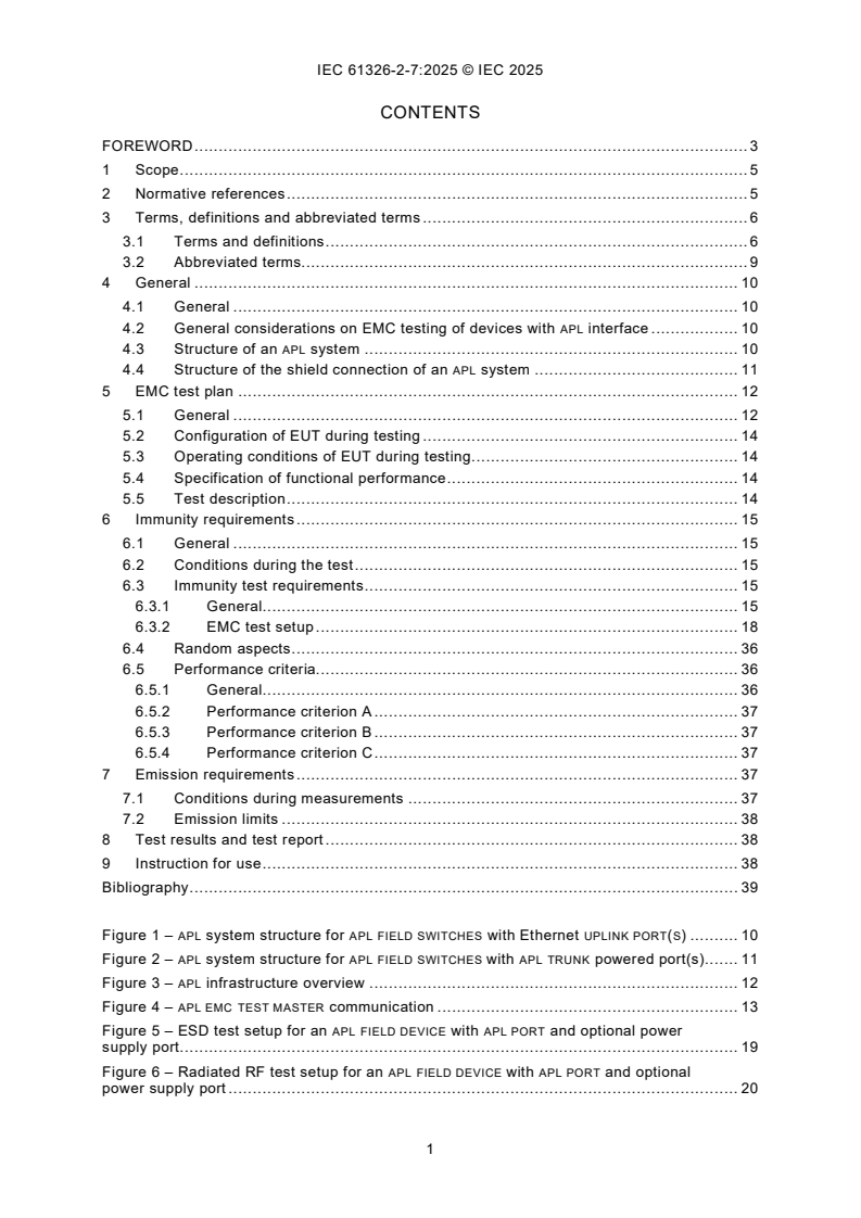
CONTENTS
FOREWORD . 3
1 Scope . 5
2 Normative references . 5
3 Terms, definitions and abbreviated terms . 6
3.1 Terms and definitions . 6
3.2 Abbreviated terms. 9
4 General . 10
4.1 General . 10
4.2 General considerations on EMC testing of devices with APL interface . 10
4.3 Structure of an APL system . 10
4.4 Structure of the shield connection of an APL system . 11
5 EMC test plan . 12
5.1 General . 12
5.2 Configuration of EUT during testing . 14
5.3 Operating conditions of EUT during testing . 14
5.4 Specification of functional performance . 14
5.5 Test description . 14
6 Immunity requirements . 15
6.1 General . 15
6.2 Conditions during the test . 15
6.3 Immunity test requirements . 15
6.3.1 General. 15
6.3.2 EMC test setup . 18
6.4 Random aspects . 36
6.5 Performance criteria. 36
6.5.1 General. 36
6.5.2 Performance criterion A . 37
6.5.3 Performance criterion B . 37
6.5.4 Performance criterion C . 37
7 Emission requirements . 37
7.1 Conditions during measurements . 37
7.2 Emission limits . 38
8 Test results and test report . 38
9 Instruction for use . 38
Bibliography . 39
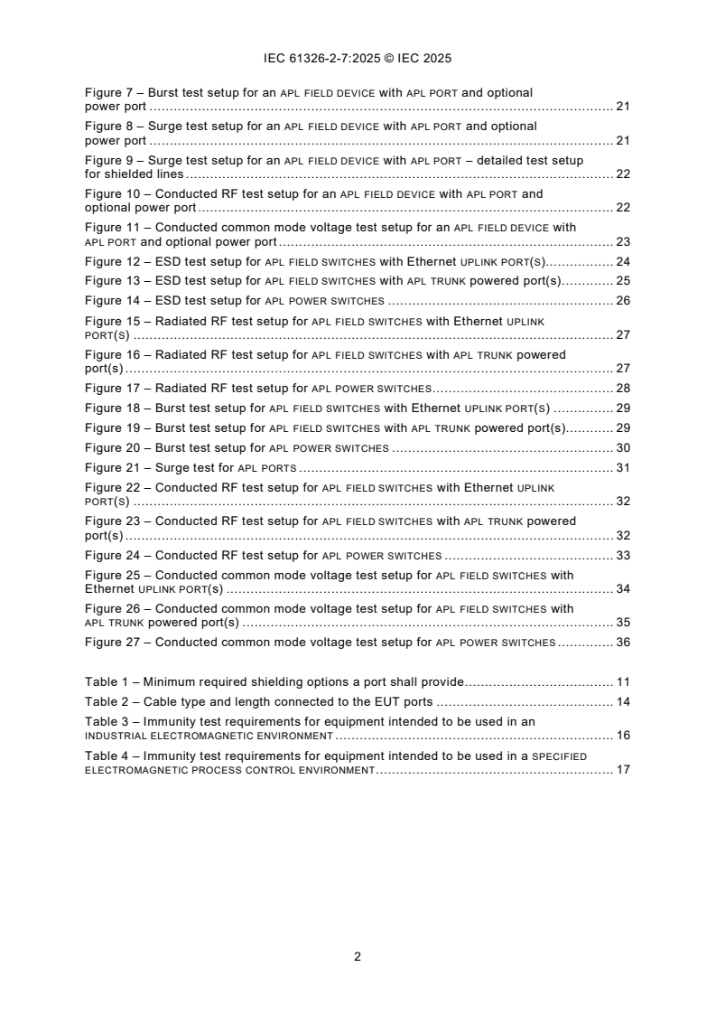
Figure 1 – APL system structure for APL FIELD SWITCHES with Ethernet UPLINK PORT(S) . 10
Figure 2 – APL system structure for APL FIELD SWITCHES with APL TRUNK powered port(s). 11
Figure 3 – APL infrastructure overview . 12
Figure 4 – APL EMC TEST MASTER communication . 13
Figure 5 – ESD test setup for an APL FIELD DEVICE with APL PORT and optional power
supply port . 19
Figure 6 – Radiated RF test setup for an APL FIELD DEVICE with APL PORT and optional
power supply port . 20
Figure 7 – Burst test setup for an APL FIELD DEVICE with APL PORT and optional
power port . 21
Figure 8 – Surge test setup for an APL FIELD DEVICE with APL PORT and optional
power port . 21
Figure 9 – Surge test setup for an APL FIELD DEVICE with APL PORT – detailed test setup
for shielded lines . 22
Figure 10 – Conducted RF test setup for an APL FIELD DEVICE with APL PORT and
optional power port . 22
Figure 11 – Conducted common mode voltage test setup for an APL FIELD DEVICE with
APL PORT and optional power port . 23
Figure 12 – ESD test setup for APL FIELD SWITCHES with Ethernet UPLINK PORT(S). 24
Figure 13 – ESD test setup for APL FIELD SWITCHES with APL TRUNK powered port(s) . 25
Figure 14 – ESD test setup for APL POWER SWITCHES . 26
Figure 15 – Radiated RF test setup for APL FIELD SWITCHES with Ethernet UPLINK
PORT(S) . 27
Figure 16 – Radiated RF test setup for APL FIELD SWITCHES with APL TRUNK powered
port(s) . 27
Figure 17 – Radiated RF test setup for APL POWER SWITCHES . 28
Figure 18 – Burst test setup for APL FIELD SWITCHES with Ethernet UPLINK PORT(S) . 29
Figure 19 – Burst test setup for APL FIELD SWITCHES with APL TRUNK powered port(s). 29
Figure 20 – Burst test setup for APL POWER SWITCHES . 30
Figure 21 – Surge test for APL PORTS . 31
Figure 22 – Conducted RF test setup for APL FIELD SWITCHES with Ethernet UPLINK
PORT(S) . 32
Figure 23 – Conducted RF test setup for APL FIELD SWITCHES with APL TRUNK powered
port(s) . 32
Figure 24 – Conducted RF test setup for APL POWER SWITCHES . 33
Figure 25 – Conducted common mode voltage test setup for APL FIELD SWITCHES with
Ethernet UPLINK PORT(s) . 34
Figure 26 – Conducted common mode voltage test setup for APL FIELD SWITCHES with
APL TRUNK powered port(s) . 35
Figure 27 – Conducted common mode voltage test setup for APL POWER SWITCHES . 36
Table 1 – Minimum required shielding options a port shall provide . 11
Table 2 – Cable type and length connected to the EUT ports . 14
Table 3 – Immunity test requirements for equipment intended to be used in an
INDUSTRIAL ELECTROMAGNETIC ENVIRONMENT . 16
Table 4 – Immunity test requirements for equipment intended to be used in a SPECIFIED
ELECTROMAGNETIC PROCESS CONTROL ENVIRONMENT . 17
INTERNATIONAL ELECTROTECHNICAL COMMISSION
____________
Electrical equipment for measurement, control and laboratory use -
EMC requirements -
Part 2-7: Particular requirements - Test configurations, operational
conditions, test levels and performance criteria
for devices with Ethernet-APL interfaces
FOREWORD
1) The International Electrotechnical Commission (IEC) is a worldwide organization for standardization comprising
all national electrotechnical committees (IEC National Committees). The object of IEC is to promote international
co-operation on all questions concerning standardization in the electrical and electronic fields. To this end and
in addition to other activities, IEC publishes International Standards, Technical Specifications, Technical Reports,
Publicly Available Specifications (PAS) and Guides (hereafter referred to as “IEC Publication(s)”). Their
preparation is entrusted to technical committees; any IEC National Committee interested in the subject dealt with
may participate in this preparatory work. International, governmental and non-governmental organizations liaising
with the IEC also participate in this preparation. IEC collaborates closely with the International Organization for
Standardization (ISO) in accordance with conditions determined by agreement between the two organizations.
2) The formal decisions or agreements of IEC on technical matters express, as nearly as possible, an international
consensus of opinion on the relevant subjects since each technical committee has representation from all
interested IEC National Committees.
3) IEC Publications have the form of recommendations for international use and are accepted by IEC National
Committees in that sense. While all reasonable efforts are made to ensure that the technical content of IEC
Publications is accurate, IEC cannot be held responsible for the way in which they are used or for any
misinterpretation by any end user.
4) In order to promote international uniformity, IEC National Committees undertake to apply IEC Publications
transparently to the maximum extent possible in their national and regional publications. Any divergence between
any IEC Publication and the corresponding national or regional publication shall be clearly indicated in the latter.
5) IEC itself does not provide any attestation of conformity. Independent certification bodies provide conformity
assessment services and, in some areas, access to IEC marks of conformity. IEC is not responsible for any
services carried out by independent certification bodies.
6) All users should ensure that they have the latest edition of this publication.
7) No liability shall attach to IEC or its directors, employees, servants or agents including individual experts and
members of its technical committees and IEC National Committees for any personal injury, property damage or
other damage of any nature whatsoever, whether direct or indirect, or for costs (including legal fees) and
expenses arising out of the publication, use of, or reliance upon, this IEC Publication or any other IEC
Publications.
8) Attention is drawn to the Normative references cited in this publication. Use of the referenced publications is
indispensable for the correct application of this publication.
9) IEC draws attention to the possibility that the implementation of this document may involve the use of (a)
patent(s). IEC takes no position concerning the evidence, validity or applicability of any claimed patent rights in
respect thereof. As of the date of publication of this document, IEC had not received notice of (a) patent(s), which
may be required to implement this document. However, implementers are cautioned that this may not represent
the latest information, which may be obtained from the patent database available at https://patents.iec.ch. IEC
shall not be held responsible for identifying any or all such patent rights.
IEC 61326-2-7 has been prepared by subcommittee 65A: System aspects, of IEC technical
committee 65: Industrial-process measurement, control and automation. It is an International
Standard.
The text of this International Standard is based on the following documents:
Draft Report on voting
65A/1190/FDIS 65A/1196/RVD
Full information on the voting for its approval can be found in the report on voting indicated in
the above table.
The language used for the development of this International Standard is English.
This document was drafted in accordance with ISO/IEC Directives, Part 2, and developed in
accordance with ISO/IEC Directives, Part 1 and ISO/IEC Directives, IEC Supplement, available
at www.iec.ch/members_experts/refdocs. The main document types developed by IEC are
described in greater detail at www.iec.ch/publications.
Words in SMALL CAPITALS in the text are defined in Clause 3.
A list of all parts of the IEC 61326 series, under the general title Electrical equipment for
measurement, control and laboratory use - EMC requirements, can be found on the IEC website.
The committee has decided that the contents of this document will remain unchanged until the
stability date indicated on the IEC website under webstore.iec.ch in the data related to the
specific document. At this date, the document will be
– reconfirmed,
– withdrawn, or
– revised.
1 Scope
In addition to the requirements of IEC 61326-1, this part of IEC 61326 specifies the EMC test
requirements for process automation equipment using at least one Ethernet-APL (Ethernet
ADVANCED PHYSICAL LAYER) compliant port according IEC TS 63444. The type of equipment
covered by this document includes INFRASTRUCTURE DEVICES such as switches as well as
measurement and control devices. This document provides requirements for the EMC test
setups of the APL interface for devices intended for use in process control and process
measurement.
The other functions of the equipment remain covered by other parts of the IEC 61326 series.
NOTE Ethernet-APL uses IEEE Std. 802.3-2022 Ethernet Physical Layer 10BASE-T1L, suitable to be used for full-
duplex communication over a single balanced pair of conductors.
The test levels are based on the intended environment as stated in the product’s specification
or user documentation and selected appropriately from IEC 61326-1.
2 Normative references
The following documents are referred to in the text in such a way that some or all of their content
constitutes requirements of this document. For dated references, only the edition cited applies.
For undated references, the latest edition of the referenced document (including any
amendments) applies.
IEC 60050-161:1990, International Electrotechnical Vocabulary (IEV) - Part 161:
Electromagnetic compatibility
IEC 61000-3-2, Electromagnetic compatibility (EMC) - Part 3-2: Limits - Limits for harmonic
current emissions (equipment input current ≤16 A per phase)
IEC 61000-3-3, Electromagnetic compatibility (EMC) - Part 3-3: Limits - Limitation of voltage
changes, voltage fluctuations and flicker in public low-voltage supply systems, for equipment
with rated current ≤16 A per phase and not subject to conditional connection
IEC 61000-3-11, Electromagnetic compatibility (EMC) - Part 3-11: Limits - Limitation of voltage
changes, voltage fluctuations and flicker in public low-voltage supply systems - Equipment with
rated current ≤ 75 A and subject to conditional connection
IEC 61000-3-12, Electromagnetic compatibility (EMC) - Part 3-12: Limits - Limits for harmonic
currents produced by equipment connected to public low-voltage systems with input current >16
A and ≤ 75 A per phase
IEC 61000-4-2:2025, Electromagnetic compatibility (EMC) - Part 4-2: Testing and measurement
techniques - Electrostatic discharge immunity test
IEC 61000-4-3:2020, Electromagnetic compatibility (EMC) - Part 4-3: Testing and measurement
techniques - Radiated, radio-frequency, electromagnetic field immunity test
IEC 61000-4-4:2012, Electromagnetic compatibility (EMC) - Part 4-4: Testing and measurement
techniques - Electrical fast transient/burst immunity test
IEC 61000-4-5:2014, Electromagnetic compatibility (EMC) - Part 4-5: Testing and measurement
techniques - Surge immunity test
IEC 61000-4-6:2023, Electromagnetic compatibility (EMC) - Part 4-6: Testing and measurement
techniques - Immunity to conducted disturbances, induced by radio-frequency fields
IEC 61000-4-8:2009, Electromagnetic compatibility (EMC) - Part 4-8: Testing and measurement
techniques - Power frequency magnetic field immunity test
IEC 61000-4-11:2020, Electromagnetic compatibility (EMC) - Part 4-11: Testing and
measurement techniques - Voltage dips, short interruptions and voltage variations immunity
tests for equipment with input current up to 16 A per phase
IEC 61000-4-16:2015, Electromagnetic compatibility (EMC) - Part 4-16: Testing and
measurement techniques - Test for immunity to conducted, common mode disturbances in the
frequency range 0 Hz to 150 kHz
IEC 61000-4-29:2000, Electromagnetic compatibility (EMC) - Part 4-29: Testing and
measurement techniques - Voltage dips, short interruptions and voltage variations on d.c. input
power port immunity tests
IEC 61326-1:2020, Electrical equipment for measurement, control and laboratory use - EMC
requirements - Part 1: General requirements
IEC TS 63444:2023, Industrial networks - Ethernet-APL port profile specification
CISPR 11:2024, Industrial, scientific and medical equipment - Radio-frequency disturbance
characteristics - Limits and methods of measurement
IEEE Std 802.3-2022, IEEE Standard for Ethernet
3 Terms, definitions and abbreviated terms
3.1 Terms and definitions
For the purposes of this document, the terms and definitions given in IEC 60050-161 and the
following apply.
ISO and IEC maintain terminology databases for use in standardization at the following
addresses:
– IEC Electropedia: available at https://www.electropedia.org/
– ISO Online browsing platform: available at https://www.iso.org/obp
3.1.1
advanced physical layer
APL
physical layer, specified in IEC TS 63444, based on 10BASE-T1L according to
IEEE Std 802.3-2022 with additional optional features like intrinsic safety, power over 2 wires
3.1.2
APL EMC test master
device used for testing the communication as well as for testing the process date integrity of a
FIELD DEVICE
Note 1 to entry: It is providing an Ethernet port, which can be directly connected to the EUT or connected to the
EUT using an APL FIELD SWITCH or APL POWER SWITCH. Additionally, the APL EMC TEST MASTER will provide at least one
failure output to indicate a disturbed communication.
3.1.3
APL field device
device with one SPUR load port which sends or receives process values
Note 1 to entry: In addition, it can have an optional power supply port.
3.1.4
APL segment
segment that consists of two F ports, each containing a 10BASE-T1L compatible PHY,
connected at each end of a two-wire, shielded cable
Note 1 to entry: An APL SEGMENT can optionally be equipped with a maximum of two AUXILIARY DEVICES and can
contain up to 10 inline terminal CONNECTIONS. An AUXILIARY DEVICE corresponds to one inline CONNECTION; for
example, having two AUXILIARY DEVICES connected to one APL SEGMENT will reduce the number of inline CONNECTIONS
by two.
Note 2 to entry: An APL SEGMENT is either a TRUNK or a SPUR.
3.1.5
APL switch
Ethernet switch including at least one APL compliant port
3.1.6
APL port
electrical and mechanical interface of a device to an APL SEGMENT
3.1.7
auxiliary device
device that is connected within an APL SEGMENT and does not include a 10BASE-T1L PHY, e.g.
it could comprise a power load or introduce communication signal insertion losses
Note 1 to entry: A surge protector is an example of an AUXILIARY DEVICE.
3.1.8
connection
inline connection
mated device or combination of devices used to connect cables or cable elements to other
cables or application specific equipment
3.1.9
cascade port
APL PORT used in powered daisy chain networks
Note 1 to entry: If the CASCADE PORT is used in a powered ring network, it shall be either a power source port or a
power load port depending on the status of the ring.
3.1.10
degradation (in performance)
undesired departure in the operational performance of any device, equipment or system from
its intended performance
Note 1 to entry: The term "DEGRADATION" can apply to temporary or permanent failure.
[SOURCE: IEC 60050-161:1990, 161-01-19]
3.1.11
field switch
APL SWITCH having at least one port to which a SPUR can be connected
3.1.12
infrastructure device
SPUR port and at least one ethernet UPLINK PORT
device with at least one
3.1.13
industrial electromagnetic environment
environment existing at locations characterized by a separate power network, in most cases
supplied from a high- or medium-voltage transformer, dedicated for the supply of installations
feeding manufacturing or similar plants with one or more of the following conditions:
– frequent switching of heavy inductive or capacitive loads,
– high currents and associated magnetic fields,
– presence of Industrial, Scientific and Medical (ISM) equipment (for example, welding
machines)
3.1.14
laboratory
test and measurement area that is specifically used for analysis, testing and servicing and
where equipment is operated by trained personnel
3.1.15
loss of function
operation of equipment with one (or more) of the equipment’s functions unusable
3.1.16
performance level
specified operation of equipment under conditions of intended use
3.1.17
long-distance line
line within a building which are longer than 30 m, or which leave the building (including lines of
outdoor installations)
3.1.18
loss of performance
operation of equipment outside a specified PERFORMANCE LEVEL
3.1.19
PHY
physical layer circuitry required to implement physical layer functions
3.1.20
power switch
switch including at least one port feeding power into a TRUNK
3.1.21
specified electromagnetic process control environment
environments encompassed both indoor and outdoor, that are based on the requirements of the
process industry, specifically chemical/petrochemical/pharmaceutical manufacturing plants
EXAMPLE The difference between this electromagnetic environment compared to the general industrial
environment (see 3.1.13) is due to the mitigation measures employed against electromagnetic phenomena leading
to a specified electromagnetic environment with test values that have been proven in practice to gain high availability.
The environment of industrial application with a specified electromagnetic environment typically includes the
following characteristics:
– industrial area with limited access,
– limited use of mobile transmitters,
– dedicated cables for power supply and control, signal or communication lines,
– separation between power supply and control, signal or communication cables,
– factory building mostly consisting of metal construction,
– overvoltage/lightning protection by appropriate measures (for example, metal construction of the building or use
of protection devices),
– pipe heating systems driven by AC main power,
– no high-voltage substation close to sensitive areas,
– presence of CISPR 11 Group 2 ISM equipment using ISM frequencies only with low power,
– competent staff,
– periodical maintenance of equipment and systems,
– mounting and installation guidelines for equipment and systems.
3.1.22
spur
APL SEGMENT which connects a field device to a FIELD SWITCH
Note 1 to entry: An APL SPUR segment can have a maximum cable length of 200 m.
Note 2 to entry: An APL SPUR segment can optionally be equipped with a maximum of two AUXILIARY DEVICES and
up to four inline terminal CONNECTIONS.
3.1.23
trunk
APL SEGMENT which connects a POWER SWITCH to a FIELD SWITCH or a FIELD SWITCH to a FIELD
SWITCH
Note 1 to entry: An APL TRUNK segment can have a maximum cable length of 1 000 m.
Note 2 to entry: An APL TRUNK segment can optionally be equipped with a maximum of two AUXILIARY DEVICES and
up to 10 inline terminal CONNECTIONS.
3.1.24
uplink port
ethernet port of an APL INFRASTRUCTURE DEVICE used for CONNECTION to the Ethernet network
3.2 Abbreviated terms
AE auxiliary equipment
APL advanced physical layer
CCC capacitive coupling clamp
CDN coupling/decoupling network
CN coupling network
EMC electromagnetic compatibility
ESD electrostatic discharge
EUT equipment under test
FIELD DEVICE
FD
HCP horizontal coupling plate
GRP ground reference plate
ICMP internet control message protocol
IP internet protocol
RF radio frequency
4 General
4.1 General
This document specifies the requirements and test setups for testing APL infrastructure and
FIELD DEVICES.
4.2 General considerations on EMC testing of devices with APL interface
The following general rules apply when testing APL devices:
– EMC testing of INFRASTRUCTURE DEVICES and field devices with APL interface is based on the
IEC 61326 series.
– Test levels and test requirements for industrial environments are provided in Table 3 of this
document. These levels are the minimum requirements for EMC testing for an APL device.
– For processing industry environments, such as chemical/petrochemical/pharmaceutical
manufacturing plants, additional tests can be required. The higher test levels required for
these environments are provided in Table 4 of this document.
All tests may either be performed on a single EUT or the tests may be split between several
EUTs. In the latter case, each test result shall be traceable to the tested EUT. The testing
sequence with multiple EUTs is optional.
4.3 Structure of an APL system
APL allows different system configurations, using 10/100/1 000 Mbit/s Ethernet network
CONNECTIONS with powered APL TRUNKS.
Figure 1 illustrates an example of an APL network connected to a control network using an
Ethernet network. In such a case, the 10/100/1 000 MBit/s Ethernet backbone is directly
connected to the APL FIELD SWITCHES. For an Ethernet network, an APL system also supports
redundant ring topologies.
Key
FD APL FIELD DEVICE
a
In case of a ring topology
Figure 1 – APL system structure for APL FIELD SWITCHES with Ethernet UPLINK PORT(S)
Figure 2 illustrates an example of an APL network connected to a control network using a
powered APL TRUNK. The communication link between the control network and the APL SEGMENT
is performed through an APL POWER SWITCH, which additionally powers the APL TRUNK. For a
powered APL TRUNK, an APL system currently does not support redundant ring topologies.
Key
FD APL FIELD DEVICE
Figure 2 – APL system structure for APL FIELD SWITCHES with APL TRUNK powered port(s)
Each APL SPUR finally terminates at a FIELD DEVICE, which can also be powered in accordance
with the applicable hazardous area classification, so that FIELD DEVICES, which will typically be
intrinsically safe certified, can be located in an appropriately assessed hazardous area.
Each TRUNK cable length can be up to 1 000 m long, depending on the type of the cable used,
the power loss through the cable and the power consumption of the components connected to
the TRUNK. The SPUR cable length can be up to 200 m, depending on the type of the cable used.
4.4 Structure of the shield connection of an APL system
The Ethernet- APL PORT profile specification specifies required shielding options depending on
the type of port (see Table 1). While it is recommended to make a low impedance connection
to the equipotential bonding system at both ends of a cable shield to guarantee the highest
rejection of electromagnetic disturbances, in some installations this can not be practical or could
lead to current loops. For this kind of installations, one end of the cable shall be capacitively
grounded and the other end shall be directly grounded.
Table 1 – Minimum required shielding options a port shall provide
Port class Segment class
TRUNK SPUR
P Power source Direct Capacitive
L Power load Capacitive and direct Direct
C CASCADE PORT Capacitive and direct Not applicable
Key
P power source
L power load
C CASCADE PORT power source
P
C CASCADE PORT power load
L
NOTE 1 If the equipotential bonding system is controlled and equalized, direct shield grounding on both sides can
be used.
NOTE 2 A C port is a CASCADE PORT operating as a source port, a C port is a CASCADE PORT operating as a power
p L
load port.
Figure 3 – APL infrastructure overview
5 EMC test plan
5.1 General
EMC tests of EUTs (APL INFRASTRUCTURE DEVICES and FIELD DEVICES) shall be applied using an
APL EMC TEST MASTER in combination with an APL FIELD SWITCH or APL POWER SWITCH, depending
on which EUT type is tested. Specific test setups for the different EUT types are provided in
6.3.2.
The APL EMC TEST MASTER shall provide an Ethernet port, which can be directly connected to the
EUT or connected to the EUT using an APL FIELD SWITCH or APL POWER SWITCH. Additionally, the
APL EMC TEST MASTER shall provide at least one failure output to indicate a disturbed
communication. Failure criteria for activating the failure output are provided in 6.5.
The APL EMC TEST MASTER may be used for testing the communication as well as for testing the
process data integrity of a FIELD DEVICE. Alternatively, two APL EMC TEST MASTERS may be used:
one for testing the communication and the second for testing the process data integrity.
To test communication, the APL EMC TEST MASTER shall continuously send ICMP ping request
packets to an IP-capable EUT and AUXILIARY EQUIPMENT devices (e.g. FIELD DEVICES or FIELD
SWITCHES) connected to the EUT to verify whether communication to these devices is valid or
disturbed. All connected APL communication ports of the EUT shall carry ICMP packets during
testing.
Figure 4 shows an example how the APL EMC TEST MASTER communicates with the EUT and the
AUXILIARY DEVICES sending ICMP ping request packets and receiving ICMP ping response
packets to check whether the communication links are active and continue to provide valid
communication during the EMC tests.
Key
Dashed lines:
ICMP ping request packets sent from APL test master to EUT and AUXILIARY DEVICES
ICMP ping response packets returned from EUT and AUXILIARY DEVICES to APL test master
Figure 4 – APL EMC TEST MASTER communication
The IPv4 ICMP ping request packets issued by the APL EMC TEST MASTER shall have a payload
data length of 1 472 bytes communicating with the EUT and each AUXILIARY DEVICE with a cycle
time of 16 ms (± 2 ms). The EUT and each AUXILIARY DEVICE shall respond with an IPv4 ICMP
response packet with a payload length of 1 472 bytes. This causes a link utilisation of minimum
7,6 %. If an alternative protocol is used, the same minimum link utilisation shall be reached.
The data packets should be equally distributed over time. If the minimum link utilisation cannot
be achieved, the test time or number of test events should be extended for all transient tests to
have the same statistical possibility to disturb the communication signal.
An IPv4 ICMP packet with a payload data length of 1 472 bytes results in the maximum allowed
Ethernet packet size of 1 518 bytes including Ethernet header and frame check sequence. For
IPv6 packets, the ICMP packet payload data length shall be reduced to 1 452 bytes, as the IPv6
IP header is 20 bytes longer than the IPv4 IP header.
In case a high number of AUXILIARY DEVICES (typically more than 10 to 12 devices) is used within
the EMC test setup, it can be necessary to reduce the ICMP packet length to get a link utilization
of less than 100 % for the APL EMC TEST MASTER. In such a case, reducing the ICMP packet
length complies with this specification.
For APL FIELD DEVICES, in addition to the ICMP ping packets, it is necessary to exchange
measurement or control data in a cyclic manner during the EMC tests. For this data exchange,
standard communication protocols may be used and shall be specified in the test plan.
An EMC test plan shall be established prior to testing. At a minimum, it shall contain the
elements specified in 5.2 to 5.5.
5.2 Configuration of EUT during testing
APL devices often are used in systems with no fixed configuration. Thus, it is reasonable to test
only a subset of possible arrangements.
To realistically simulate EMC conditions (related both to emission and immunity), the equipment
assembly shall represent a typical installation as specified by the manufacturer. Such tests shall
be carried out as type tests under normal conditions as specified in the test plan.
The detailed test setup during the EMC test shall be documented.
5.3 Operating conditions of EUT during testing
The EUT shall be used in normal operation. The estimated worst-case operating mode for
normal operation shall be selected.
5.4 Specification of functional performance
For immunity tests, the functional performance for each test shall be specified, where possible,
as quantitative values (e.g. communication error rate or allowed measurement tolerances).
5.5 Test description
Each test to be applied shall be specified in the EMC test plan. The description of the tests, the
test methods, the characteristics of the tests, and the test setups are given in the basic
standards, which are referred to in 6.2 and Clause 7. Additional information needed for the
practical implementation of the tests is given in this document. It is not necessary to reproduce
the contents of the referenced standards in the test plan. Where necessary, the EMC test plan
shall specify the application in detail.
The cable configurations in Table 2 shall apply for all test setups specified in 6.2 and Clause 7.
Table 2 – Cable type and length connected to the EUT ports
Port type Cable type, length
a
Ethernet port
CAT 6A S/FTP Ethernet cable, 20 m
Power supply Adequate cable type and length
a
APL TRUNK
IEC TS 63444 AWG 18 fieldbus cable, 20 m
a
APL SPUR
IEC TS 63444 AWG 18 fieldbus cable, 20 m
NOTE Instead of a cable defined in IEC TS 63444, an SPE cable in accordance with IEC 61156-13 can be used.
a
Background for these requirements is that a cable length of 20 m, especially if wound as 50 cm (± 5 cm) cable
coils, can be easily handled in EMC lab environments and be used for all the different test scenarios (including
surge test). By specifying a unified cable length for all APL-specific EMC tests, the test results between different
EMC test labs are expected to be better comparable.
If an EUT port provides both direct and capacitive shield grounding options, the correct
behaviour of the EUT shall be tested for both options.
IF the EUT provides only one port of a specific type (e.g. APL TRUNK port or APL SPUR port), the
tests shall be applied sequentially using the different shield grounding options.
If the EUT provides more than one port of a specific type, test efforts may be reduced by setting
up one port using direct shield grounding and another port of the same specific type using
capacitive shield grounding. For example, testing a FIELD SWITCH with at least two APL TRUNK
ports and at least two APL SPUR ports, a test setup can use one APL TRUNK port with direct shield
grounding, one APL TRUNK port with capacitive shield grounding, one APL SPUR port with direct
shield grounding and one APL SPUR port with capacitive shield grounding being configured.
The connection of the shield grounding for the AE (auxiliary equipment) used with a FIELD
SWITCH as an EUT shall be selected according to the test plan. See Figure 3. For other APL
devices (e.g. FIELD DEVICES), it shall be done according to Figure 3.
If the EUT has a DC power port, the EMC test setup shall be supplied by an isolated power
supply or a battery. There shall be no connection of the output of the power supply or battery
to ground. If the EUT has an AC power port, the EMC test setup shall be supplied directly from
the mains or from a power source that is not isolated from ground.
6 Immunity requirements
6.1 General
This clause specifies the immunity test requirements for APL infrastructure and FIELD DEVICES,
the conditions during the test and the given immunity test levels for the expected EMC
environment.
6.2 Conditions during the test
The configuration of the EUT and the modes of operation used during the execution of each
test shall be precisely noted in the test report. The tests shall be performed in accordance with
the basic standards listed in the relevant table for one phenomenon at a time. If additional test
conditions or configurations not described in the basic standards are required, these conditions
or configurations, and their rationale, shall be documented in the test report.
6.3 Immunity test requirements
6.3.1 General
The minimum immunity requirements for equipment intended to be used in an INDUSTRIAL
ELECTROMAGNETIC ENVIRONMENT are given in Table 3.
If required, Table 4 gives the immunity requirements for equipment intended to be used in a
SPECIFIED ELECTROMAGNETIC PROCESS CONTROL environment like
chemical/petrochemical/pharmaceutical manufacturing plants.
The performance criteria A, B and C that are mentioned in the following tables are specified in
6.5.
Table 3 – Immunity test requirements for equipment intended to be used in an
INDUSTRIAL ELECTROMAGNETIC ENVIRONMENT
Performance
Port Phenomenon Basic standard Test value
criterion
ENCLOSURE ESD IEC 61000-4-2 ± 4 kV contact discharge B
± 8 kV air discharge B
Electromagnetic field IEC 61000-4-3 10 V/m (80 MHz to 1 GHz) A
a
A
3 V/m (1,4 GHz to 6 GHz)
Power-frequency magnetic IEC 61000-4-8 30 A/m (50 Hz, 60 Hz) A
b
field
AC power Burst IEC 61000-4-4 ± 2 kV (5 kHz or 100 kHz) B
(including
Surge IEC 61000-4-5 ± 1 kV line-to-line B
protective earth)
± 2 kV line-to-ground B
Conducted RF IEC 61000-4-6 3 V (150 kHz to 80 MHz) A
See NOTE
Voltage dip IEC 61000-4-11 0 % during 1 cycle B
c
C
40 % during 10/12 cycles
c C
70 % during 25/30 cycles
c
Short interruptions IEC 61000-4-11 C
0 % during 250/300 cycles
d, e
Burst IEC 61000-4-4 ± 2 kV (5 kHz or 100 kHz) B
DC power
(including Surge IEC 61000-4-5 ± 1 kV line-to-line B
protective earth)
± 2 kV line-to-ground B
Conducted RF IEC 61000-4-6 3 V (150 kHz to 80 MHz) A
See NOTE
d
I/O signal / IEC 61000-4-4 ± 1 kV (5 kHz or 100 kHz) B
Burst
e, g
control / APL
f
IEC 61000-4-5 ± 1 kV line-to-ground B
Surge
(including
d
IEC 61000-4-6 3 V (150 kHz to 80 MHz) A
Conducted RF
functional earth)
See NOTE
d
I/O signal / IEC 61000-4-4 ± 2 kV (5 kHz or 100 kHz) B
Burst
e
control
f
IEC 61000-4-5 ± 1 kV line-to-line B
Surge
(connected
± 2 kV line-to-ground B
directly to mains
d
supply) IEC 61000-4-6 3 V (150 kHz to 80 MHz) A
Conducted RF
See NOTE
NOTE Equipment considered in this table is typically used in industrial installations with the cabling arranged on
metallic structures. This reduces coupling of electromagnetic fields into cables and hence justifies a lower immunity
level compared to that given in the generic immunity standard IEC 61000-6-2. The level of 3 V has been used for
more than 15 years without immunity issues and hence is considered to be sufficient.
a
In case testing is performed also in the frequency range from 1 GHz to 1,4 GHz, the same test level as above
1,4 GHz is recommended.
b
On
...
IEC 61326-2-7 ®
Édition 1.0 2025-12
NORME
INTERNATIONALE
Matériel électrique de mesure, de commande et de laboratoire - Exigences
relatives à la CEM -
Partie 2-7: Exigences particulières - Configurations d'essai, conditions de
fonctionnement, niveaux d'essai et critères de performance applicables aux
dispositifs équipés d'interfaces Ethernet-APL
ICS 17.220.20; 25.040.40; 33.100.20 ISBN 978-2-8327-1599-4
Droits de reproduction réservés. Sauf indication contraire, aucune partie de cette publication ne peut être reproduite ni
utilisée sous quelque forme que ce soit et par aucun procédé, électronique ou mécanique, y compris la photocopie et
les microfilms, sans l'accord écrit de l'IEC ou du Comité national de l'IEC du pays du demandeur. Si vous avez des
questions sur le copyright de l'IEC ou si vous désirez obtenir des droits supplémentaires sur cette publication, utilisez
les coordonnées ci-après ou contactez le Comité national de l'IEC de votre pays de résidence.
IEC Secretariat Tel.: +41 22 919 02 11
3, rue de Varembé info@iec.ch
CH-1211 Geneva 20 www.iec.ch
Switzerland
A propos de l'IEC
La Commission Electrotechnique Internationale (IEC) est la première organisation mondiale qui élabore et publie des
Normes internationales pour tout ce qui a trait à l'électricité, à l'électronique et aux technologies apparentées.
A propos des publications IEC
Le contenu technique des publications IEC est constamment revu. Veuillez vous assurer que vous possédez l’édition la
plus récente, un corrigendum ou amendement peut avoir été publié.
Recherche de publications IEC - IEC Products & Services Portal - products.iec.ch
webstore.iec.ch/advsearchform Découvrez notre puissant moteur de recherche et consultez
La recherche avancée permet de trouver des publications gratuitement tous les aperçus des publications, symboles
IEC en utilisant différents critères (numéro de référence, graphiques et le glossaire. Avec un abonnement, vous aurez
texte, comité d’études, …). Elle donne aussi des toujours accès à un contenu à jour adapté à vos besoins.
informations sur les projets et les publications remplacées
ou retirées. Electropedia - www.electropedia.org
Le premier dictionnaire d'électrotechnologie en ligne au
IEC Just Published - webstore.iec.ch/justpublished monde, avec plus de 22 500 articles terminologiques en
Restez informé sur les nouvelles publications IEC. Just anglais et en français, ainsi que les termes équivalents
dans 25 langues additionnelles. Egalement appelé
Published détaille les nouvelles publications parues.
Disponible en ligne et une fois par mois par email. Vocabulaire Electrotechnique International (IEV) en ligne.
Service Clients - webstore.iec.ch/csc
Si vous désirez nous donner des commentaires sur cette
publication ou si vous avez des questions contactez-
nous: sales@iec.ch.
SOMMAIRE
AVANT-PROPOS . 3
1 Domaine d'application . 5
2 Références normatives . 5
3 Termes, définitions et abréviations . 6
3.1 Termes et définitions . 6
3.2 Abréviations . 10
4 Généralités . 10
4.1 Généralités . 10
4.2 Considérations générales relatives aux essais de CEM des dispositifs avec
l'interface APL . 10
4.3 Structure d'un système APL . 10
4.4 Structure de raccordement à l'écran d'un système APL . 12
5 Plan d'essai de CEM . 14
5.1 Généralités . 14
5.2 Configuration de l'EUT lors des essais . 16
5.3 Conditions de fonctionnement de l'EUT lors des essais . 16
5.4 Spécification des performances fonctionnelles . 16
5.5 Description de l'essai . 16
6 Exigences relatives à l'immunité . 17
6.1 Généralités . 17
6.2 Conditions lors de l'essai . 18
6.3 Exigences pour les essais d'immunité . 18
6.3.1 Généralités . 18
6.3.2 Montage d'essai de CEM . 20
6.4 Aspects aléatoires . 49
6.5 Critères de performance . 49
6.5.1 Généralités . 49
6.5.2 Critère de performance A. 49
6.5.3 Critère de performance B. 49
6.5.4 Critère de performance C . 50
7 Exigences relatives à l'émission . 50
7.1 Conditions applicables pendant les mesurages . 50
7.2 Limites d'émission . 50
8 Résultats d'essai et rapport d'essai . 51
9 Instructions pour l'utilisation . 51
Bibliographie . 52
Figure 1 – Structure de système APL pour COMMUTATEURS DE CHAMP APL avec un ou
plusieurs ACCES DE LIAISON MONTANTE Ethernet . 11
Figure 2 – Structure de système APL pour COMMUTATEURS DE CHAMP APL avec un ou
plusieurs accès alimentés de LIGNE PRIMAIRE APL . 12
Figure 3 – Vue d'ensemble de l'infrastructure APL . 13
Figure 4 – Communication du MAITRE D'ESSAI DE CEM DE L'APL . 15
Figure 5 – Montage d'essai DES pour un DISPOSITIF DE TERRAIN APL avec ACCES APL et
accès d'alimentation facultatif . 22
Figure 6 – Montage d'essai de RF rayonnée pour un DISPOSITIF DE TERRAIN APL avec
ACCES APL et accès d'alimentation facultatif . 23
Figure 7 – Montage d'essai en salves pour un DISPOSITIF DE TERRAIN APL avec ACCES
APL et accès d'alimentation facultatif . 24
Figure 8 – Montage d'essai de tension de choc pour un DISPOSITIF DE TERRAIN APL avec
ACCES APL et accès d'alimentation facultatif . 25
Figure 9 – Montage d'essai de tension de choc pour un DISPOSITIF DE TERRAIN APL avec
ACCES APL – Vue détaillée du montage d'essai pour lignes blindées . 26
Figure 10 – Montage d'essai de perturbations RF conduites pour un DISPOSITIF DE
TERRAIN APL avec ACCES APL et accès d'alimentation facultatif . 27
Figure 11 – Montage d'essai de tension conduite en mode commun pour un DISPOSITIF
DE TERRAIN APL avec ACCES APL et accès d'alimentation facultatif . 28
Figure 12 – Montage d'essai DES pour COMMUTATEURS DE CHAMP APL avec un ou
plusieurs ACCES DE LIAISON MONTANTE Ethernet . 30
Figure 13 – Montage d'essai DES pour COMMUTATEURS DE CHAMP APL avec un ou
plusieurs accès alimentés de LIGNE PRIMAIRE APL . 31
Figure 14 – Montage d'essai DES pour COMMUTATEURS DE PUISSANCE APL . 32
Figure 15 – Montage d'essai de perturbations RF rayonnées pour COMMUTATEURS DE
CHAMP APL avec un ou plusieurs ACCES DE LIAISON MONTANTE Ethernet . 34
Figure 16 – Montage d'essai de perturbations RF rayonnées pour COMMUTATEURS DE
CHAMP APL avec un ou plusieurs accès alimentés de LIGNE PRIMAIRE APL . 35
Figure 17 – Montage d'essai de perturbations RF rayonnées pour COMMUTATEURS DE
PUISSANCE APL . 36
Figure 18 – Montage d'essai de salve pour COMMUTATEURS DE CHAMP APL avec un ou
plusieurs ACCES DE LIAISON MONTANTE Ethernet . 38
Figure 19 – Montage d'essai de salve pour COMMUTATEURS DE CHAMP APL avec un ou
plusieurs accès alimentés de LIGNE PRIMAIRE APL . 39
Figure 20 – Montage d'essai de salve pour COMMUTATEURS DE PUISSANCE APL . 40
Figure 21 – Essai de tension de choc pour ACCES APL . 41
Figure 22 – Montage d'essai de perturbations RF conduites pour COMMUTATEURS DE
CHAMP APL avec un ou plusieurs ACCES DE LIAISON MONTANTE Ethernet . 42
Figure 23 – Montage d'essai de perturbations RF conduites pour COMMUTATEURS DE
CHAMP APL avec un ou plusieurs accès alimentés de LIGNE PRIMAIRE APL . 43
Figure 24 – Montage d'essai de perturbations RF conduites pour COMMUTATEURS DE
PUISSANCE APL . 44
Figure 25 – Montage d'essai de tension conduite en mode commun pour
COMMUTATEURS DE CHAMP APL avec un ou plusieurs ACCES DE LIAISON MONTANTE
Ethernet . 46
Figure 26 – Montage d'essai de tension conduite en mode commun pour
COMMUTATEURS DE CHAMP APL avec un ou plusieurs accès alimentés de LIGNE
PRIMAIRE APL . 47
Figure 27 – Montage d'essai de tension conduite en mode commun pour
COMMUTATEURS DE PUISSANCE APL . 48
Tableau 1 – Options de blindage minimales exigées qu'un accès doit fournir . 13
Tableau 2 – Type et longueur des câbles raccordés aux accès de l'EUT . 17
Tableau 3 – Exigences pour les essais d'immunité des équipements destinés à être
utilisés dans un ENVIRONNEMENT ELECTROMAGNETIQUE INDUSTRIEL . 18
Tableau 4 – Exigences pour les essais d'immunité des équipements destinés à être
utilisés dans un ENVIRONNEMENT ELECTROMAGNETIQUE SPECIFIE DE COMMANDE DE
ROCESSUS . 19
COMMISSION ÉLECTROTECHNIQUE INTERNATIONALE
____________
Matériel électrique de mesure, de commande et de laboratoire -
Exigences relatives à la CEM -
Partie 2-7: Exigences particulières - Configurations d'essai, conditions de
fonctionnement, niveaux d'essai et critères de performance applicables
aux dispositifs équipés d'interfaces Ethernet-APL
AVANT-PROPOS
1) La Commission Électrotechnique Internationale (IEC) est une organisation mondiale de normalisation composée
de l'ensemble des comités électrotechniques nationaux (Comités nationaux de l'IEC). L'IEC a pour objet de
favoriser la coopération internationale pour toutes les questions de normalisation dans les domaines de
l'électricité et de l'électronique. À cet effet, l'IEC – entre autres activités – publie des Normes internationales,
des Spécifications techniques, des Rapports techniques, des Spécifications accessibles au public (PAS) et des
Guides (ci-après dénommés "Publication(s) de l'IEC"). Leur élaboration est confiée à des comités d'études, aux
travaux desquels tout Comité national intéressé par le sujet traité peut participer. Les organisations
internationales, gouvernementales et non gouvernementales, en liaison avec l'IEC, participent également aux
travaux. L'IEC collabore étroitement avec l'Organisation Internationale de Normalisation (ISO), selon des
conditions fixées par accord entre les deux organisations.
2) Les décisions ou accords officiels de l'IEC concernant les questions techniques représentent, dans la mesure du
possible, un accord international sur les sujets étudiés, étant donné que les Comités nationaux de l'IEC intéressés
sont représentés dans chaque comité d'études.
3) Les Publications de l'IEC se présentent sous la forme de recommandations internationales et sont agréées
comme telles par les Comités nationaux de l'IEC. Tous les efforts raisonnables sont entrepris afin que l'IEC
s'assure de l'exactitude du contenu technique de ses publications; l'IEC ne peut pas être tenue responsable de
l'éventuelle mauvaise utilisation ou interprétation qui en est faite par un quelconque utilisateur final.
4) Dans le but d'encourager l'uniformité internationale, les Comités nationaux de l'IEC s'engagent, dans toute la
mesure possible, à appliquer de façon transparente les Publications de l'IEC dans leurs publications nationales
et régionales. Toutes divergences entre toutes Publications de l'IEC et toutes publications nationales ou
régionales correspondantes doivent être indiquées en termes clairs dans ces dernières.
5) L'IEC elle-même ne fournit aucune attestation de conformité. Des organismes de certification indépendants
fournissent des services d'évaluation de conformité et, dans certains secteurs, accèdent aux marques de
conformité de l'IEC. L'IEC n'est responsable d'aucun des services effectués par les organismes de certification
indépendants.
6) Tous les utilisateurs doivent s'assurer qu'ils sont en possession de la dernière édition de cette publication.
7) Aucune responsabilité ne doit être imputée à l'IEC, à ses administrateurs, employés, auxiliaires ou mandataires,
y compris ses experts particuliers et les membres de ses comités d'études et des Comités nationaux de l'IEC,
pour tout préjudice causé en cas de dommages corporels et matériels, ou de tout autre dommage de quelque
nature que ce soit, directe ou indirecte, ou pour supporter les coûts (y compris les frais de justice) et les dépenses
découlant de la publication ou de l'utilisation de cette Publication de l'IEC ou de toute autre Publication de l'IEC,
ou au crédit qui lui est accordé.
8) L'attention est attirée sur les références normatives citées dans cette publication. L'utilisation de publications
référencées est obligatoire pour une application correcte de la présente publication.
9) L'IEC attire l'attention sur le fait que la mise en application du présent document peut entraîner l'utilisation d'un
ou de plusieurs brevets. L'IEC ne prend pas position quant à la preuve, à la validité et à l'applicabilité de tout
droit de brevet revendiqué à cet égard. À la date de publication du présent document, l'IEC n'avait pas reçu
notification qu'un ou plusieurs brevets pouvaient être nécessaires à sa mise en application. Toutefois, il y a lieu
d'avertir les responsables de la mise en application du présent document que des informations plus récentes
sont susceptibles de figurer dans la base de données de brevets, disponible à l'adresse https://patents.iec.ch.
L'IEC ne saurait être tenue pour responsable de ne pas avoir identifié de tels droits de brevets.
L'IEC 61326-2-7 a été établie par le sous-comité 65A: Aspects systèmes, du comité études 65
de l'IEC: Mesure, commande et automation dans les processus industriels. Il s'agit d'une Norme
internationale.
La présente version bilingue (2026-11) correspond à la version anglaise monolingue publiée en
2025-12.
La version française de cette norme n'a pas été soumise au vote.
La langue employée pour l'élaboration de cette Norme internationale est l'anglais.
Ce document a été rédigé selon les Directives ISO/IEC, Partie 2, il a été développé selon les
Directives ISO/IEC, Partie 1 et les Directives ISO/IEC, Supplément IEC, disponibles sous
www.iec.ch/members_experts/refdocs. Les principaux types de documents développés par
l'IEC sont décrits plus en détail sous www.iec.ch/publications.
Les termes en PETITES MAJUSCULES dans le texte sont définis à l'Article 3.
Une liste de toutes les parties de la série IEC 61326, publiées sous le titre général Matériel
électrique de mesure, de commande et de laboratoire, se trouve sur le site web de l'IEC.
Le comité a décidé que le contenu de ce document ne sera pas modifié avant la date de stabilité
indiquée sur le site web de l'IEC sous webstore.iec.ch dans les données relatives au document
recherché. À cette date, le document sera
– reconduit,
– supprimé, ou
– révisé.
1 Domaine d'application
En plus des exigences données dans l'IEC 61326-1, la présente partie de l'IEC 61326 spécifie
les exigences d'essai en matière de CEM pour les équipements d'automatisation de processus
COUCHE PHYSIQUE AVANCEE Ethernet) conforme à
utilisant au moins un accès Ethernet-APL (
l'IEC TS 63444. Le type d'équipement couvert par le présent document comprend les
DISPOSITIFS D'INFRASTRUCTURE tels que les commutateurs ainsi que les dispositifs de mesure et
de commande. Le présent document fournit des exigences relatives aux montages d'essai de
CEM de l'interface APL pour les dispositifs destinés à être utilisés pour la commande et la
mesure des processus.
Les autres fonctions du matériel sont toujours couvertes par les autres parties de la série
IEC 61326.
NOTE Ethernet-APL utilise la couche physique Ethernet 10BASE-T1L de l'IEEE Std. 802.3-2022, adaptée à une
utilisation dans le cadre de la communication en duplex intégral sur une seule paire équilibrée de conducteurs.
Les niveaux d'essai sont fondés sur l'environnement prévu, tel qu'indiqué dans la spécification
du produit ou la documentation d'utilisation, et choisis de manière appropriée dans
l'IEC 61326 -1.
2 Références normatives
Les documents suivants sont cités dans le texte de sorte qu'ils constituent, pour tout ou partie
de leur contenu, des exigences du présent document. Pour les références datées, seule
l'édition citée s'applique. Pour les références non datées, la dernière édition du document de
référence s'applique (y compris les éventuels amendements).
IEC 60050-161:1990, Vocabulaire Électrotechnique International (IEV) - Partie 161:
Compatibilité électromagnétique
IEC 61000-3-2, Compatibilité électromagnétique (CEM) - Partie 3-2: Limites - Limites pour les
émissions de courant harmonique (courant appelé par les appareils ≤ 16 A par phase)
IEC 61000-3-3, Compatibilité électromagnétique (CEM) - Partie 3-3: Limites - Limitation des
variations de tension, des fluctuations de tension et du papillotement dans les réseaux publics
d'alimentation basse tension, pour les matériels ayant un courant assigné ≤ 16 A par phase et
non soumis à un raccordement conditionnel
IEC 61000-3-11, Compatibilité électromagnétique (CEM) - Partie 3-11: Limites - Limitation des
variations de tension, des fluctuations de tension et du papillotement dans les réseaux publics
d'alimentation basse tension - Équipements ayant un courant assigné inférieur ou égal à ≤ 75
A et soumis à un raccordement conditionnel
IEC 61000-3-12, Compatibilité électromagnétique (CEM) - Partie 3-12: Limites - Limites pour
les courants harmoniques produits par les appareils connectés aux réseaux publics basse
tension ayant un courant appelé > 16 A et ≤ 75 A par phase
IEC 61000-4-2:2025, Compatibilité électromagnétique (CEM) - Partie 4-2: Techniques d'essai
et de mesure - Essai d'immunité aux décharges électrostatiques
IEC 61000-4-3:2020, Compatibilité électromagnétique (CEM) - Partie 4-3: Techniques d'essai
et de mesure - Essai d'immunité aux champs électromagnétiques rayonnés aux fréquences
radioélectriques
IEC 61000-4-4:2012, Compatibilité électromagnétique (CEM) - Partie 4-4: Techniques d'essai
et de mesure - Essais d'immunité aux transitoires électriques rapides en salves
IEC 61000-4-5:2014, Compatibilité électromagnétique (CEM) - Partie 4-5: Techniques d'essai
et de mesure - Essai d'immunité aux ondes de choc
IEC 61000-4-6:2023, Compatibilité électromagnétique (CEM) - Partie 4-6: Techniques d'essai
et de mesure - Immunité aux perturbations conduites, induites par les champs aux fréquences
radioélectriques
IEC 61000-4-8:2009, Compatibilité électromagnétique (CEM) - Partie 4-8: Techniques d'essai
et de mesure - Essai d'immunité au champ magnétique à la fréquence du réseau
IEC 61000-4-11:2020, Compatibilité électromagnétique (CEM) - Partie 4-11: Techniques
d'essai et de mesure - Essais d'immunité aux creux de tension, coupures brèves et variations
de tension pour les appareils à courant d'entrée inférieur ou égal à 16 A par phase
IEC 61000-4-16:2015, Compatibilité électromagnétique (CEM) - Partie 4-16: Techniques
d'essai et de mesure - Essai d'immunité aux perturbations conduites en mode commun dans la
plage de fréquences de 0 Hz à 150 kHz
IEC 61000-4-29:2000, Compatibilité électromagnétique (CEM) - Partie 4-29: Techniques
d'essai et de mesure - Essais d'immunité aux creux de tension, coupures brèves et variations
de tension sur les accès d'alimentation en courant continu
IEC 61326-1:2020, Matériel électrique de mesure, de commande et de laboratoire - Exigences
relatives à la CEM - Partie 1: Exigences générales
IEC TS 63444:2023, Industrial networks - Ethernet-APL port profile specification (disponible en
anglais seulement)
CISPR 11:2024, Appareils industriels, scientifiques et médicaux - Caractéristiques de
perturbations radioélectriques - Limites et méthodes de mesure
IEEE Std 802.3-2022, IEEE Standard for Ethernet (disponible en anglais seulement)
3 Termes, définitions et abréviations
3.1 Termes et définitions
Pour les besoins du présent document, les termes et définitions de l'IEC 60050-161 ainsi que
les suivants s'appliquent.
L'ISO et l'IEC tiennent à jour des bases de données terminologiques destinées à être utilisées
en normalisation, consultables aux adresses suivantes:
– IEC Electropedia: disponible à l'adresse https://www.electropedia.org/
– ISO Online browsing platform: disponible à l'adresse https://www.iso.org/obp
3.1.1
couche physique avancée
APL
couche physique, spécifiée dans l'IEC TS 63444, fondée sur la norme 10BASE-T1L selon
l'IEEE Std 802.3-2022 avec des fonctions supplémentaires facultatives telles que la sécurité
intrinsèque ou la puissance sur deux fils
Note 1 à l'article: L'abréviation 'APL" est dérivée du terme anglais développé correspondant "advanced physical
layer".
3.1.2
maître d'essai de CEM de l'APL
dispositif utilisé pour soumettre à essai la communication ainsi que l'intégrité des données de
processus d'un DISPOSITIF DE TERRAIN
Note 1 à l'article: Il fournit un accès Ethernet, qui peut être directement connecté à l'EUT ou connecté à ce dernier
en utilisant un COMMUTATEUR DE CHAMP APL ou un COMMUTATEUR DE PUISSANCE APL. En outre, le MAITRE D'ESSAI DE
CEM DE L'APL fournit au moins une sortie de défaillance permettant d'indiquer une perturbation de la communication.
3.1.3
dispositif de terrain APL
dispositif muni d'un accès de charge de DERIVATION qui envoie ou reçoit des valeurs de
processus
Note 1 à l'article: Il peut également posséder un accès d'alimentation en option.
3.1.4
segment APL
segment constitué de deux accès F comportant chacun un circuit PHY compatible 10BASE-T1L,
relié à chaque extrémité d'un câble blindé à deux fils
Note 1 à l'article: Un SEGMENT APL peut éventuellement être équipé d'un maximum de deux DISPOSITIFS AUXILIAIRES
et peut comporter jusqu'à 10 CONNEXIONS de borne en ligne. Un DISPOSITIF AUXILIAIRE correspond à une CONNEXION
EN LIGNE. Par exemple, deux DISPOSITIFS AUXILIAIRES raccordés à un SEGMENT APL réduiront de deux le nombre de
CONNEXIONS en ligne disponibles.
Note 2 à l'article: Un SEGMENT APL est soit une LIGNE PRIMAIRE, soit une DERIVATION.
3.1.5
commutateur APL
commutateur Ethernet comprenant au moins un accès conforme à l'APL
3.1.6
accès APL
interface électrique et mécanique d'un dispositif avec un SEGMENT APL
3.1.7
dispositif auxiliaire
dispositif connecté dans un SEGMENT APL et qui ne comprend pas de circuit PHY compatible
10BASE-T1L, il peut par exemple comporter une charge électrique ou introduire des pertes
d'insertion du signal de communication
Note 1 à l'article: Un dispositif de protection contre les surtensions est un exemple de DISPOSITIF AUXILIAIRE.
3.1.8
connexion
connexion en ligne
dispositif accouplé ou combinaison de dispositifs utilisés pour raccorder des câbles ou des
éléments de câbles à d'autres câbles ou appareils spécifiques à l'application
3.1.9
accès en cascade
ACCES APL utilisé dans les réseaux à chaîne d'éléments en boucle alimentés
Note 1 à l'article: Si l'ACCES EN CASCADE est utilisé dans un réseau en anneau alimenté, il doit s'agir d'un accès de
source d'alimentation ou d'un accès de charge électrique, en fonction de l'état de l'anneau.
3.1.10
dégradation (de fonctionnement)
écart non désiré des caractéristiques de fonctionnement d'un dispositif, d'un appareil ou d'un
système par rapport aux caractéristiques attendues
Note 1 à l'article: Une DEGRADATION peut être un défaut de fonctionnement temporaire ou permanent.
[SOURCE: IEC 60050-161:1990, 161-01-19]
3.1.11
commutateur de champ
COMMUTATEUR APL qui comporte au moins un accès sur lequel une DERIVATION peut être
connectée
3.1.12
dispositif d'infrastructure
dispositif qui comporte au moins un accès de DERIVATION et au moins un ACCES DE LIAISON
MONTANTE Ethernet
3.1.13
environnement électromagnétique industriel
environnement existant dans des lieux caractérisés par un réseau électrique distinct, fourni
dans la plupart des cas à partir d'un transformateur à haute ou moyenne tension, dédié à
l'approvisionnement d'installations alimentant des usines de fabrication ou similaires et
présentant l'une ou plusieurs des conditions suivantes:
– la commutation fréquente d'importantes charges inductives ou capacitives;
– la présence de courants élevés et des champs magnétiques associés;
– la présence d'équipements industriels, scientifiques et médicaux (ISM) (par exemple,
soudeuses)
3.1.14
laboratoire
zone d'essai et de mesure spécifiquement utilisée à des fins d'analyse, d'essai et d'entretien,
et dont les équipements sont utilisés par du personnel formé
3.1.15
perte de fonction
fonctionnement de l'équipement alors qu'(au moins) une de ses fonctions est inutilisable
3.1.16
niveau de performance
fonctionnement spécifié d'un équipement dans les conditions d'utilisation prévue
3.1.17
ligne à grande distance
ligne de plus de 30 m située à l'intérieur ou sortant d'un bâtiment (y compris les lignes
d'installations extérieures)
3.1.18
perte de performance
NIVEAU DE PERFORMANCE spécifié
fonctionnement de l'équipement en dehors d'un
3.1.19
PHY
circuit de la couche physique exigé pour la mise en œuvre des fonctions de la couche physique
3.1.20
commutateur de puissance
commutateur comprenant au moins un accès assurant l'alimentation électrique d'une LIGNE
PRIMAIRE
3.1.21
environnement électromagnétique spécifié de commande de processus
environnements tant intérieurs qu'extérieurs, fondés sur les exigences de l'industrie de
transformation, en particulier les usines de fabrication de produits
chimiques/pétrochimiques/pharmaceutiques
EXEMPLE La différence entre cet environnement électromagnétique et l'environnement industriel général (voir
3.1.13) tient aux mesures d'atténuation mises en œuvre contre les phénomènes électromagnétiques et qui
conduisent à un environnement électromagnétique spécifié pour lequel les valeurs d'essai ont permis de démontrer
en pratique la grande disponibilité.
L'environnement d'application industrielle et son environnement électromagnétique spécifié présentent généralement
les caractéristiques suivantes:
– zone industrielle à accès limité;
– utilisation limitée des émetteurs mobiles;
– câbles dédiés aux lignes d'alimentation, de commande, de signal ou de communication;
– séparation entre les câbles d'alimentation, de commande, de signal ou de communication;
– bâtiment d'usine principalement constitué d'une construction métallique;
– protection contre les surtensions/la foudre assurée par des mesures appropriées (par exemple, construction
métallique du bâtiment ou utilisation de dispositifs de protection);
– systèmes de chauffage des tuyaux alimentés par l'alimentation principale en courant alternatif;
– absence de poste à haute tension à proximité des zones sensibles;
– présence d'équipements ISM relevant du Groupe 2 de la CISPR 11 utilisant uniquement des fréquences ISM à
faible puissance;
– personnel compétent,
– maintenance périodique des équipements et systèmes;
– application de lignes directrices pour le montage et l'installation des équipements et systèmes.
3.1.22
dérivation
SEGMENT APL qui relie un dispositif de terrain à un COMMUTATEUR DE CHAMP
Note 1 à l'article: Un segment de DERIVATION APL peut avoir une longueur de câble maximale de 200 m.
Note 2 à l'article: Un segment de DERIVATION APL peut éventuellement être équipé d'un maximum de deux
DISPOSITIFS AUXILIAIRES et comporter jusqu'à quatre CONNEXIONS de borne en ligne.
3.1.23
ligne primaire
SEGMENT APL qui relie un COMMUTATEUR DE PUISSANCE à un COMMUTATEUR DE CHAMP ou un
COMMUTATEUR DE CHAMP à un COMMUTATEUR DE CHAMP
Note 1 à l'article: Un segment de LIGNE PRIMAIRE APL peut avoir une longueur de câble maximale de 1 000 m.
Note 2 à l'article: Un segment de LIGNE PRIMAIRE APL peut éventuellement être équipé d'un maximum de deux
DISPOSITIFS AUXILIAIRES et comporter jusqu'à 10 CONNEXIONS de borne en ligne.
3.1.24
accès de liaison montante
accès Ethernet d'un DISPOSITIF D'INFRASTRUCTURE APL utilisé pour la CONNEXION au réseau
Ethernet
3.2 Abréviations
AE (Auxiliary Equipment) équipement auxiliaire
APL (Advanced Physical Layer) couche physique
CCC (Capacitive Coupling Clamp) pince de couplage capacitif
CDN (Coupling/Decoupling Network) réseau de couplage/découplage
CN (Coupling Network) réseau de couplage
CEM compatibilité électromagnétique
DES décharge électrostatique
EUT (Equipment Under Test) équipement en essai
FD (Field Device) DISPOSITIF DE TERRAIN
HCP (Horizontal Coupling Plate) plan de couplage horizontal
GRP (Ground Reference Plate) plan du sol de référence
ICMP (Internet Control Message Protocol) protocole des messages de commande
Internet
IP (Internet Protocol) protocole Internet
RF radiofréquence
4 Généralités
4.1 Généralités
Le présent document spécifie les exigences et les montages d'essai pour la mise à l'essai de
l'infrastructure APL et des DISPOSITIFS DE TERRAIN.
4.2 Considérations générales relatives aux essais de CEM des dispositifs avec
l'interface APL
Les règles générales suivantes s'appliquent lors de la mise à l'essai des dispositifs APL:
– Les essais de CEM des DISPOSITIFS D'INFRASTRUCTURE et des dispositifs de terrain avec
l'interface APL sont fondés sur la série IEC 61326.
– Les niveaux d'essai et les exigences d'essai pour les environnements industriels sont
spécifiés dans le Tableau 3 du présent document. Ces niveaux correspondent aux
exigences minimales pour les essais de CEM des dispositifs APL.
– Pour les environnements de l'industrie de transformation, tels que les usines de fabrication
de produits chimiques/pétrochimiques/pharmaceutiques, des essais supplémentaires
peuvent être exigés. Les niveaux d'essai les plus élevés exigés pour ces environnements
sont spécifiés dans le Tableau 4 du présent document.
Tous les essais peuvent être effectués sur un EUT unique ou les essais peuvent être répartis
entre plusieurs EUT. Dans ce dernier cas, chaque résultat d'essai doit être traçable jusqu'à
l'EUT concerné. La séquence d'essai impliquant plusieurs EUT est facultative.
4.3 Structure d'un système APL
L'APL permet la mise en place de différentes configurations de système, en utilisant des
CONNEXIONS réseau Ethernet de 10/100/1 000 Mbit/s avec des LIGNES PRIMAIRES APL
alimentées.
La Figure 1 donne un exemple de réseau APL connecté à un réseau de commande utilisant un
réseau Ethernet. Dans ce cas, le réseau Ethernet dorsal de 10/100/1 000 MBit/s est
directement connecté aux COMMUTATEURS DE CHAMP APL. Dans un réseau Ethernet, un système
APL prend également en charge des topologies en anneau redondantes.
Anglais Français
Auxiliary power Alimentation auxiliaire
Ethernet backbone Réseau Ethernet central
a a
Ethernet backbone Réseau Ethernet central
APL FIELD SWITCH with Ethernet uplink port(s) COMMUTATEUR DE CHAMP APL avec un ou plusieurs
accès de liaison montante Ethernet
APL SPUR DÉRIVATION APL
FD FD
Légende
FD DISPOSITIF DE TERRAIN APL
a
Dans le cas d'une topologie en anneau
Figure 1 – Structure de système APL pour COMMUTATEURS DE CHAMP APL
avec un ou plusieurs ACCES DE LIAISON MONTANTE Ethernet
La Figure 2 représente un réseau APL connecté à un réseau de commande utilisant une LIGNE
PRIMAIRE APL alimentée. La liaison de communication entre le réseau de commande et le
SEGMENT APL est effectuée par l'intermédiaire d'un COMMUTATEUR DE PUISSANCE APL qui assure
également l'alimentation de la LIGNE PRIMAIRE APL. Dans le cas d'une LIGNE PRIMAIRE APL
alimentée, un système APL n'est actuellement pas en mesure de prendre en charge les
topologies en anneau redondantes.
Anglais Français
Auxiliary power Alimentation auxiliaire
Ethernet backbone Réseau Ethernet central
APL power switch Commutateur de puissance APL
APL powered TRUNK LIGNE PRIMAIRE alimentée APL
APL FIELD SWITCH with TRUNK powered port(s) COMMUTATEUR DE CHAMP APL avec un ou plusieurs
accès alimentés de LIGNE PRIMAIRE
APL SPUR DÉRIVATION APL
FD FD
Légende
DISPOSITIF DE TERRAIN APL
FD
Figure 2 – Structure de système APL pour COMMUTATEURS DE CHAMP APL
avec un ou plusieurs accès alimentés de LIGNE PRIMAIRE APL
DERIVATION APL aboutit à un DISPOSITIF DE TERRAIN qui peut également être alimenté
Chaque
conformément à la classification applicable des zones dangereuses, de sorte que les
DISPOSITIFS DE TERRAIN, qui sont généralement certifiés intrinsèquement sûrs, peuvent être
situés dans une zone dangereuse évaluée en conséquence.
Chaque câble de LIGNE PRIMAIRE peut avoir une longueur inférieure ou égale à 1 000 m, en
fonction type de câble utilisé, de la perte de puissance due au câble et de la consommation
LIGNE PRIMAIRE. Le câble de DERIVATION peut avoir
électrique des composants raccordés à la
une longueur inférieure ou égale à 200 m, en fonction du type de câble utilisé.
4.4 Structure de raccordement à l'écran d'un système APL
La spécification de profil d'ACCES Ethernet-APL précise les options de blindage exigées en
fonction du type d'accès (voir Tableau 1). Bien qu'il soit recommandé d'établir une connexion
à faible impédance avec le système de liaison équipotentielle aux deux extrémités d'un blindage
de câble afin de limiter autant que possible les perturbations électromagnétiques, dans
certaines installations, cette solution peut s'avérer peu pratique, voire entraîner la formation de
boucles de courant. Lorsque c'est le cas, l'une des extrémités du câble doit être mise à la terre
de manière capacitive, tandis que l'autre extrémité doit être mise à la terre de manière directe.
Tableau 1 – Options de blindage minimales exigées qu'un accès doit fournir
Classe de l'accès Classe du segment
LIGNE PRIMAIRE DERIVATION
P Source d'alimentation Directe Capacitive
L Charge électrique Capacitive et directe Directe
C ACCES EN CASCADE Capacitive et directe Non applicable
Anglais Français
Power switch Commutateur de puissance
Optional Facultatif
FIELD DEVICE DISPOSITIF DE TERRAIN
Légende
P source d'alimentation
L charge électrique
C source d'alimentation de l'ACCES EN CASCADE
P
C charge électrique de l'ACCES EN CASCADE
L
NOTE 1 Si le système de liaison équipotentielle est régulé et équilibré, une mise à la terre directe du blindage des
deux côtés peut être utilisée.
NOTE 2 Un accès C est un ACCES EN CASCADE fonctionnant comme un accès source, un accès C est un ACCES
p L
EN CASCADE fonctionnant comme un accès de charge électrique.
Figure 3 – Vue d'ensemble de l'infrastructure APL
5 Plan d'essai de CEM
5.1 Généralités
Les essais CEM des EUT (DISPOSITIFS D'INFRASTRUCTURE et DISPOSITIFS DE TERRAIN APL)
doivent être appliqués à l'aide d'un MAITRE D'ESSAI DE CEM DE L'APL, associé à un COMMUTATEUR
DE CHAMP APL ou un COMMUTATEUR DE PUISSANCE APL, en fonction du type d'EUT soumis à
essai. Des montages d'essai spécifiques aux différents types d'EUT sont présentés au 6.3.2.
Le MAITRE D'ESSAI DE CEM DE L'APL doit comporter un accès Ethernet, lequel peut être relié à
l'EUT directement ou par l'intermédiaire d'un COMMUTATEUR DE CHAMP APL ou d'un
COMMUTATEUR DE PUISSANCE APL. De plus, le MAITRE D'ESSAI DE CEM DE L'APL doit comporter
au moins une sortie de défaillance afin d'indiquer toute perturbation de la communication. Les
critères de défaillance déclenchant l'activation de la sortie de défaillance sont présentés au 6.5.
Le MAITRE D'ESSAI DE CEM DE L'APL peut être utilisé pour la mise à l'essai de la communication
ainsi que pour mettre à l'essai l'intégrité des données de processus d'un DISPOSITIF DE TERRAIN.
En variante, deux MAITRES D'ESSAI DE CEM DE L'APL peuvent être utilisés: l'un pour soumettre
à essai la communication et l'autre pour soumettre à essai l'intégrité des données de processus.
Pour soumettre à essai la communication, le MAITRE D'ESSAI DE CEM DE L'APL doit envoyer en
continu des paquets de demande Ping ICMP à un EUT compatible IP et aux dispositifs d'un
EQUIPEMENT AUXILIAIRE (par exemple DISPOSITIFS DE TERRAIN ou COMMUTATEURS DE CHAMP) reliés
à l'EUT afin de vérifier si la communication avec ces dispositifs est valide ou perturbée. Tous
les accès de communication APL connectés de l'EUT doivent transporter des paquets ICMP
pendant les essais.
L'exemple de la Figure 4 illustre la manière dont le MAITRE D'ESSAI DE CEM DE L'APL
communique avec l'EUT et les DISPOSITIFS AUXILIAIRES en envoyant des paquets de demande
Ping ICMP et en recevant des paquets de réponse Ping ICMP pour vérifier si les liaisons de
communication sont actives et continuer à fournir une communication valide pendant les essais
CEM.
Anglais Français
APL EMC test master Maître d'essai de CEM de l'APL
APL power switch Commutateur de puissance APL
APL TRUNK power port Accès d'alimentation de LIGNE PRIMAIRE APL
APL TRUNK (cascade) load port Accès de charge (en cascade) de LIGNE PRIMAIRE
APL
APL field switch with APL TRUNK powered port(s) Commutateur de champ APL avec un ou plusieurs
accès alimentés de LIGNE PRIMAIRE APL
APL TRUNK cascade power port Accès alimenté en cascade de LIGNE PRIMAIRE APL
EUT (APL field switch with APL TRUNK powered EUT (commutateur de champ APL avec un ou plusieurs
port(s)) accès alimentés de LIGNE PRIMAIRE APL)
APL field device 1 Dispositif de terrain APL 1
APL SPUR load port Accès de charge de DÉRIVATION APL
APL field device 2 Dispositif de terrain APL 2
APL SPUR power port Accès d'alimentation de DÉRIVATION APL
Légende
Lignes en pointillés:
Paquets de demande Ping ICMP envoyés du maître d'essai APL à l'EUT et aux DISPOSITIFS AUXILIAIRES
Paquets de réponse Ping ICMP renvoyés de l'EUT et des DISPOSITIFS AUXILIAIRES vers le maître d'essai APL
Figure 4 – Communication du MAITRE D'ESSAI DE CEM DE L'APL
Les paquets de demande Ping ICMP IPv4 émis par le MAITRE D'ESSAI DE CEM DE L'APL doivent
avoir une longueur de données utiles de 1 472 octets lors de la communication avec l'EUT et
chaque DISPOSITIF AUXILIAIRE pour un temps de cycle de 16 ms (± 2 ms). L'EUT et chaque
DISPOSITIF AUXILIAIRE doivent répondre par un paquet de réponse ICMP IPv4 d'une longueur
utile de 1 472 octets. Cela entraîne une utilisation de la liaison d'au moins 7,6 %. Si un autre
protocole est utilisé, la même utilisation minimale de la liaison doit être atteinte. Il convient que
les paquets de données soient répartis de manière régulière dans le temps. Si l'utilisation
minimale de la liaison ne peut pas être atteinte, il convient d'étendre la durée d'essai ou le
nombre d'événements d'essai pour tous les essais transitoires afin d'obtenir la même possibilité
statistique de perturber le signal de communication.
Un paquet ICMP IPv4 d'une longueur de données utiles de 1 472 octets permet d'obtenir la
taille de paquet Ethernet maximale autorisée de 1 518 octets, y compris l'en-tête Ethernet et la
séquence de vérification de trame. Pour les paquets IPv6, la longueur des données utiles des
paquets ICMP doit être réduite à 1 452 octets, car l'en-tête IP en IPv6 est plus long de 20 octets
par rapport à l'en-tête IP en IPv4.
Si un no
...