


prEN 14509-5
(Main)Factory-made double skin metal faced insulating sandwich panels - Part 5: Design methods
General Information
- Abstract
This document specifies design methods for combination of actions and spans for factory made double skin metal faced insulating sandwich panels (hereafter sandwich panels). The sandwich panels are for use in self-supporting and structural applications in roofs, in external and internal walls (including partitions) and in ceilings in buildings as well as those in cold store applications.
This document covers uniformly distributed loads, line loads perpendicular to the span over the full width of the panel and thermal gradients, it gives no information about normal forced axially loaded sandwich panels, torsional loaded sandwich panels or sandwich panels as a part of a diaphragm.
- Status
- Not Published
- Publication Date
- 12-Jul-2027
- Current Stage
- 4020 - Submission to enquiry - Enquiry
- Start Date
- 27-Aug-2026
- Due Date
- 24-Feb-2026
- Completion Date
- 27-Aug-2026

Overview
prEN 14509-5 is the draft European Standard developed by CEN (European Committee for Standardization) that outlines the design methods for factory-made double skin metal faced insulating sandwich panels. These sandwich panels are widely used in the construction industry due to their exceptional thermal insulation, structural performance, and versatility. The standard focuses on the correct combination of actions-such as loads and spans-ensuring safe usage in various building elements, including self-supporting roofs, external and internal walls, partitions, ceilings, and cold storage applications.
This document replaces and further develops Annex E of EN 14509:2013, specifically addressing design practices for panels with metal (non-steel) facings. When EN 1993-7 Eurocode is available, it will provide design guidance for steel-faced panels, while prEN 14509-5 covers other metal-faced sandwich panels.
Key Topics
- Combination of Actions and Spans: Specifies calculation methods to assess the combined effects of uniformly distributed loads, line loads perpendicular to the span, and thermal gradients.
- Types of Loads: Includes detailed guidance on permanent loads (self-weight, attached components), variable loads (such as wind, snow, seismic, live loads), and long-term effects (e.g., creep and thermal actions).
- Design Criteria: Outlines procedures for both ultimate limit state (ULS) and serviceability limit state (SLS), ensuring panels perform safely under all anticipated conditions.
- Material Properties: Emphasizes the importance of accurately determining properties like shear strength, modulus of elasticity, panel geometry, and interaction between faces and core.
- Testing and Calculations: Refers to related test methods and provides principles for analytical and empirical verification, including methods for determining characteristic and design values.
- Panel Applications: Details specific guidelines for different panel configurations, such as flat, lightly profiled, and fully profiled faces, and the influence of panel edges and fixings.
Applications
Insulating sandwich panels designed under prEN 14509-5 are suitable for a wide range of structural and self-supporting building applications:
- Roofs: Provides stability, weather resistance, and insulation for industrial and commercial roofing systems.
- External and Internal Walls: Used as structural elements or partitions, offering durability, energy efficiency, and ease of installation.
- Ceilings: Enhances acoustic and thermal insulation while supporting structural loads in various building types.
- Cold Storage Facilities: Optimizes temperature control and hygrothermal performance in refrigerated warehouses and processing areas.
Designers, manufacturers, and specifiers use the standard to ensure compliance with safety, durability, and performance requirements, especially where panels are exposed to combined mechanical and thermal actions. The standard supports improved quality control through standardized design criteria and encourages innovation in panel configurations and materials.
Related Standards
Implementation of prEN 14509-5 frequently involves alignment with other critical European standards and Eurocodes, including:
- EN 14509-3: Test methods for determining mechanical strength, building physics performance, and durability of sandwich panels.
- EN 14509-4: Methods for testing the performance of panel fixings and assessing their restraining effect on supporting structures.
- EN 1990 (Eurocode - Basis of Structural Design): Provides fundamental principles for the reliability and safety of structures.
- EN 1991 Series: Specifies actions on structures, including snow (EN 1991-1-3), wind (EN 1991-1-4), and thermal actions (EN 1991-1-5).
- EN 1993 Series: Design rules for steel structures, relevant for steel-faced sandwich panels (EN 1993-1-3, EN 1993-1-4).
- EN 1998-1: Seismic design for structural elements.
- EN 1999-1-4: Structural design guidance for aluminium sheeting.
- ASTM E903, C1371, E1980: Methods for determining surface temperature and solar reflectance.
prEN 14509-5 is a vital resource for achieving reliable, high-performance building envelopes using factory-made insulating metal sandwich panels with double-skin construction, supporting energy efficiency and safety in modern construction.
Get Certified
Connect with accredited certification bodies for this standard

DIBt (Deutsches Institut für Bautechnik)
German Institute for Building Technology.
DIN CERTCO
DIN Group product certification.

Aboma Certification B.V.
Specialized in construction, metal, and transport sectors.
Sponsored listings
Frequently Asked Questions
prEN 14509-5 is a draft published by the European Committee for Standardization (CEN). Its full title is "Factory-made double skin metal faced insulating sandwich panels - Part 5: Design methods". This standard covers: This document specifies design methods for combination of actions and spans for factory made double skin metal faced insulating sandwich panels (hereafter sandwich panels). The sandwich panels are for use in self-supporting and structural applications in roofs, in external and internal walls (including partitions) and in ceilings in buildings as well as those in cold store applications. This document covers uniformly distributed loads, line loads perpendicular to the span over the full width of the panel and thermal gradients, it gives no information about normal forced axially loaded sandwich panels, torsional loaded sandwich panels or sandwich panels as a part of a diaphragm.
This document specifies design methods for combination of actions and spans for factory made double skin metal faced insulating sandwich panels (hereafter sandwich panels). The sandwich panels are for use in self-supporting and structural applications in roofs, in external and internal walls (including partitions) and in ceilings in buildings as well as those in cold store applications. This document covers uniformly distributed loads, line loads perpendicular to the span over the full width of the panel and thermal gradients, it gives no information about normal forced axially loaded sandwich panels, torsional loaded sandwich panels or sandwich panels as a part of a diaphragm.
prEN 14509-5 is classified under the following ICS (International Classification for Standards) categories: 91.100.60 - Thermal and sound insulating materials. The ICS classification helps identify the subject area and facilitates finding related standards.
prEN 14509-5 is available in PDF format for immediate download after purchase. The document can be added to your cart and obtained through the secure checkout process. Digital delivery ensures instant access to the complete standard document.
Standards Content (Sample)
SLOVENSKI STANDARD
01-november-2026
Tovarniško izdelane izolacijske sendvič plošče z obojestranskim kovinskim
oplaščenjem - 5. del: Metode izračuna
Factory-made double skin metal faced insulating sandwich panels - Part 5: Design
methods
Werkmäßig hergestellte Sandwich-Elemente mit beidseitigen Metalldeckschichten - Teil
5: Berechnungsmethoden
Panneaux sandwichs isolants à deux parements métalliques manufacturés - Partie 5 :
Méthodes de conception
Ta slovenski standard je istoveten z: prEN 14509-5
ICS:
91.100.60 Materiali za toplotno in Thermal and sound insulating
zvočno izolacijo materials
2003-01.Slovenski inštitut za standardizacijo. Razmnoževanje celote ali delov tega standarda ni dovoljeno.
DRAFT
EUROPEAN STANDARD
NORME EUROPÉENNE
EUROPÄISCHE NORM
August 2026
ICS 91.100.60
English Version
Factory-made double skin metal faced insulating sandwich
panels - Part 5: Design methods
Panneaux sandwichs isolants à deux parements Werkmäßig hergestellte Sandwich-Elemente mit
métalliques manufacturés - Partie 5 : Méthodes de beidseitigen Metalldeckschichten - Teil 5:
conception Berechnungsmethoden
This draft European Standard is submitted to CEN members for enquiry. It has been drawn up by the Technical Committee
CEN/TC 128.
If this draft becomes a European Standard, CEN members are bound to comply with the CEN/CENELEC Internal Regulations
which stipulate the conditions for giving this European Standard the status of a national standard without any alteration.
This draft European Standard was established by CEN in three official versions (English, French, German). A version in any other
language made by translation under the responsibility of a CEN member into its own language and notified to the CEN-CENELEC
Management Centre has the same status as the official versions.
CEN members are the national standards bodies of Austria, Belgium, Bulgaria, Croatia, Cyprus, Czech Republic, Denmark, Estonia,
Finland, France, Germany, Greece, Hungary, Iceland, Ireland, Italy, Latvia, Lithuania, Luxembourg, Malta, Netherlands, Norway,
Poland, Portugal, Republic of North Macedonia, Romania, Serbia, Slovakia, Slovenia, Spain, Sweden, Switzerland, Türkiye and
United Kingdom.
Recipients of this draft are invited to submit, with their comments, notification of any relevant patent rights of which they are
aware and to provide supporting documentation.
Warning : This document is not a European Standard. It is distributed for review and comments. It is subject to change without
notice and shall not be referred to as a European Standard.
EUROPEAN COMMITTEE FOR STANDARDIZATION
COMITÉ EUROPÉEN DE NORMALISATION
EUROPÄISCHES KOMITEE FÜR NORMUNG
CEN-CENELEC Management Centre: Rue de la Science 23, B-1040 Brussels
© 2026 CEN All rights of exploitation in any form and by any means reserved Ref. No. prEN 14509-5:2026 E
worldwide for CEN national Members.
Contents Page
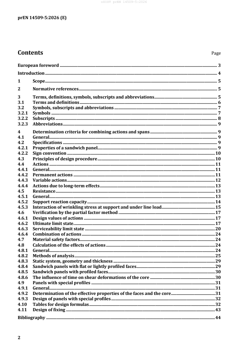
European foreword . 3
Introduction . 4
1 Scope . 5
2 Normative references . 5
3 Terms, definitions, symbols, subscripts and abbreviations . 5
3.1 Terms and definitions . 6
3.2 Symbols, subscripts and abbreviations . 7
3.2.1 Symbols . 7
3.2.2 Subscripts . 8
3.2.3 Abbreviations . 9
4 Determination criteria for combining actions and spans . 9
4.1 General. 9
4.2 Specifications . 9
4.2.1 Properties of a sandwich panel. 9
4.2.2 Sign convention . 10
4.3 Principles of design procedure . 10
4.4 Actions . 11
4.4.1 General. 11
4.4.2 Permanent actions . 11
4.4.3 Variable actions . 12
4.4.4 Actions due to long-term effects . 13
4.5 Resistance . 13
4.5.1 General. 13
4.5.2 Support reaction capacity . 14
4.5.3 Interaction of wrinkling stress at support and under line load. 15
4.6 Verification by the partial factor method . 17
4.6.1 Design values of actions . 17
4.6.2 Ultimate limit state . 17
4.6.3 Serviceability limit state . 20
4.6.4 Combination of actions . 24
4.7 Material safety factors. 24
4.8 Calculation of the effects of actions . 24
4.8.1 General. 24
4.8.2 Methods of analysis . 25
4.8.3 Static system, geometry and thickness . 29
4.8.4 Sandwich panels with flat or lightly profiled faces . 29
4.8.5 Sandwich panels with profiled faces . 30
4.8.6 The influence of time on shear deformations of the core . 30
4.9 Panels with special profiles . 31
4.9.1 General. 31
4.9.2 Determination of the effective properties of the faces and the core . 31
4.9.3 Design of panels with special profiles . 32
4.10 Tables for design formulas . 32
4.11 Design of fixing . 43
Bibliography . 44
European foreword
This document (prEN 14509-5:2026) has been prepared by Technical Committee CEN/TC 128 “Roof
covering products for discontinuous laying and products for wall cladding”, the secretariat of which is
held by NBN.
This document is currently submitted to the CEN Enquiry.
Introduction
This document covers Annex E in EN 14509:2013 and will be replaced for steel faced sandwich panels by
EN 1993-7 when this Eurocode for design of steel faced sandwich panels will be published. For sandwich
panels with other metal faces, this document will be used.
In prEN 14509-3:2026, methods for the determination of characteristics given in this document are
given.
In prEN 14509-4:2026, methods for the determination of fixing performance of panels and restraining
effect on supporting structures are given.
1 Scope
This document specifies design methods for combination of actions and spans for factory made double
skin metal faced insulating sandwich panels (hereafter sandwich panels). The sandwich panels are for
use in self-supporting and structural applications in roofs, in external and internal walls (including
partitions) and in ceilings in buildings as well as those in cold store applications.
This document covers uniformly distributed loads, line loads perpendicular to the span over the full
width of the panel and thermal gradients, it gives no information about normal forced axially loaded
sandwich panels, torsional loaded sandwich panels or sandwich panels as a part of a diaphragm.
2 Normative references
The following documents are referred to in the text in such a way that some or all of their content
constitutes requirements of this document. For dated references, only the edition cited applies. For
undated references, the latest edition of the referenced document (including any amendments) applies.
EN 1990-1, Eurocode — Basis of structural and geotechnical design — Part 1: New structures
EN 1991-1-3, Eurocode 1 — Actions on structures — Part 1-3: Snow loads
EN 1991-1-4, Eurocode 1 — Actions on structures — Part 1-4: Wind actions
EN 1991-1-5, Eurocode 1 — Actions on structures — Part 1-5: Thermal actions
EN 1993-1-3:2024, Eurocode 3 — Design of steel structures — Part 1-3: Cold-formed members and sheeting
EN 1993-1-4:2025, Eurocode 3 — Design of steel structures — Part 1-4: Stainless steel structures
EN 1998-1:2005, Eurocode 8: Design of structures for earthquake resistance — Part 1: General rules,
seismic actions and rules for buildings
EN 1999-1-4:2023, Eurocode 9 — Design of aluminium structures — Part 1-4: Cold-formed structural
sheeting
EN 10143:2006, Continuously hot-dip coated steel sheet and strip — Tolerances on dimensions and shape
prEN 14509-3:2026, Factory made double skin metal faced insulating sandwich panels — Part 3: Test
methods for determining mechanical strength, building physical behaviour and durability
prEN 14509-4:2026, Factory made double skin metal faced insulating sandwich panels — Part 4: Test
methods for fixing of panels and for determining restraining effect on substructure
3 Terms, definitions, symbols, subscripts and abbreviations
For the purposes of this document, the following terms and definitions apply.
ISO and IEC maintain terminology databases for use in standardization at the following addresses:
— ISO Online browsing platform: available at https://www.iso.org/obp/
— IEC Electropedia: available at https://www.electropedia.org/
3.1 Terms and definitions
3.1.1
bending moment capacity
maximum bending moment recorded during a test on an individual panel
3.1.2
bending resistance
characteristic value of bending moment capacity determined on the basis of a test series
3.1.3
bond
adhesion between the face(s) and the core normally provided by an adhesive
3.1.4
ceiling
covering over an internal area
3.1.5
core
layer of material, having thermal insulating properties, which is bonded between two metal faces
Note 1 to entry: Panels with special edge details in the longitudinal joints may utilize different core materials from
the main insulating core (e.g. for improved fire performance) if these edge details do not influence on mechanical
performance of the panel.
3.1.6
edge
side of the panel where adjacent panels join together in the same plane
3.1.7
face
flat, lightly profiled or profiled thin metal sheet firmly bonded to the core
3.1.8
flat face
face without any rolled or pressed profile, or raised strengthening rib
3.1.9
joint
interface between two panels where the meeting edges have been designed to allow the panels to join
together in the same plane
Note 1 to entry: The joint may incorporate interlocking parts that enhance the mechanical properties of the system
as well as improve the thermal, acoustic and fire performance and restrict air movement.
Note 2 to entry: The term ‘joint’ does not refer to a junction between cut panels or a junction where the panels are
not installed in the same plane.
3.1.10
lightly profiled face
face with a rolled or pressed profile not exceeding 5 mm in depth
3.1.11
profiled face
face with a rolled or pressed profile exceeding 5 mm in depth
3.1.12
line loads perpendicular to the span
loads that are applied on the whole width of the panel with a load application length corresponding to
the minimum support width Ls according to EN 14509 (all parts)
3.1.13
sandwich panel
building product consisting of two metal faces positioned on either side of a core, which is firmly bonded
to both faces so that the three components act compositely when under load
3.1.14
wrinkling strength
characteristic value of wrinkling stress
3.1.15
wrinkling stress
stress in the compressed face of a panel undergoing failure in bending where the failure mode takes the
form of a “wrinkle” extending over the full width of the panel near the section of maximum bending
moment
3.2 Symbols, subscripts and abbreviations
For the purposes of this document, the following symbols and subscripts apply
3.2.1 Symbols
The following symbols apply to this document
A cross-sectional area
B overall width of the panel, flexural rigidity
NOTE A, cross sectional area and B, flexural rigidity, can apply either to the full width of a panel (e.g. in
prEN 14509-3:2026 when interpreting test results) or to a unit (metre) width of panel when carrying out design
calculations or preparing load tables.
C design value of a serviceability criterion
D overall depth of the panel
E modulus of elasticity, design value of the effect of an action
F force, load
G shear modulus, permanent action
I moment of inertia
L span, distance
M bending moment
N axial compressive force
Q variable action
R resistance, reflectivity (R )
G
S shear rigidity, characteristic value of an action
T temperature
V shear force
Σ sum
d depth of face profile or stiffeners, depth of core (d )
c
e distance between centroids of faces, base of natural logarithms (e = 2,718 282)
f strength, yield stress
h height of profile
k parameter (prEN 14509-3:2026, 4.11, 4.5.3 in this document used for support reaction
capacity), correction factor
n number of webs
q live load
s length of web (s )
w1
t thickness of face sheet
v variance factor
α coefficient of thermal expansion
β parameter (Table 6, 7, 10, 11 design formulae)
γ partial safety factor, load factor (γ )
F
φ creep coefficient
θ parameter (Table 5, 6, 7 design formulae)
σ bending stress, compressive strength, standard deviation
τ shear stress
ψ combination coefficient
3.2.2 Subscripts
The following subscripts apply to this document.
C core
F face, action (γ )
F
G permanent load, degree
M material (γ )
M
Q variable action
S sandwich part of the cross-section
c compression, core
d design
i, j index
k characteristic value
lt long-term (storage loads, temperature loads in cold-storage rooms)
mt medium-term (snow loads)
nom nominal
s support (L = support width), surface (R )
s s1
st short-term (wind, temperature loads from climate actions)
supp support
t time
tol tolerance (normal or special)
0 basic value
1 external face, upper face
2 internal face, lower face
3.2.3 Abbreviations
SLS serviceability limit state
ULS ultimate limit state
4 Determination criteria for combining actions and spans
4.1 General
This clause concerns provisions that the designer has to take into account, if not otherwise specified and
which are not yet included in the relevant Eurocodes.
The supporting structure shall be sufficiently stiff, to avoid unintended diaphragm actions or composite
actions.
4.2 Specifications
4.2.1 Properties of a sandwich panel
The cross-section and material properties of a sandwich panel shall be as shown in Figures 1 a) and 1 b)
and Table 1.
a) flat, lightly profiled or micro profiled face
b) Panel cross-section, profiled face
Figure 1 — Panel cross-sections
Table 1 — Panel properties
Layer Geometry Material properties Structural properties
Face 1 t , d , d , A , I E , α B
1 11 12 F1 F1 F1 F1 F1
Core d E , G S
C C C
Face 2 t , d , d , A , I E , α B
2 21 22 F2 F2 F2 F2 F2
4.2.2 Sign convention
Where relevant, the formulae in this document assume the following sign convention: Bending moments
are negative when face 1 is in tension.
Compressive forces and stresses are positive. Downward loads are positive.
Downward deflections are positive.
4.3 Principles of design procedure
The design values E of the effects of the actions shall be calculated and shall be compared with the design
d
values of the corresponding resistance R or the relevant serviceability criterion C taking into account
d d
the appropriate material partial factors γ .
M
It shall be verified by means of calculation that the Formulae (1) to (4) are satisfied using the procedures
in 4.5 to 4.8.
Ultimate limit state: E ≤ R (1)
ULS;d d
Serviceability limit state: E ≤ C (2)
SLS;d d
where
E and E are design values of the effects of the actions, i.e.
ULS;d SLS;d
E =∑γψ⋅⋅ S
is the sum of the design values of actions (3)
d Fi i ki
R
k
R =
is the design value of the resistance at the ultimate limit state (4)
d
γ
M
is the limiting design value of the relevant serviceability criterion
C
k
C =
expressed as the maximum serviceability limit state design stress or
d
γ
M,ser
limit on deflection taking into account the material partial factor for
;
serviceability limit state design γM,ser
S is the characteristic value of an action;
ki
γ is the relevant load factor defined in EN 1990-1 in combination with
Fi
national annexes to EN 1990-1;
Ψ is the relevant combination factor;
i
γ is the relevant material partial factor in ULS;
M
γ is the relevant material partial factor in SLS;
M,ser
are the calculated or experimental value of the characteristic
k k
R , C
resistance.
NOTE The procedures conform to the “European Recommendations for Sandwich Panels: Part 1: Design” [2]
and present a sub-set of the more detailed procedures which are given in these Recommendations.
The load levels and the levels of safety may be specific to each Member State.
4.4 Actions
4.4.1 General
The actions in 4.4.2 to 4.4.4 shall be taken into account in the calculations. They shall be considered either
individually or in combination using the combination factors in 4.6 and 4.7. When panels are used for
restraining of supporting structures the moment m (see EN 1993-1-3:2024, 11.4.2.1) shall be taken into
account.
4.4.2 Permanent actions
The permanent actions to be taken into account in the design shall include the following:
— self-weight of the panel (calculated from the nominal dimensions and mean densities);
— mass of any permanent components of the structure and installation that apply load to the panel;
— permanent imposed deformations, e.g. due to temperatures in cold stores (calculated using nominal
values relevant to the specific application).
4.4.3 Variable actions
The variable actions shall include the following, where they are relevant:
— snow (quasi-permanent action);
— live loads (e.g. due to access to a roof or ceiling);
— wind loads;
— construction loads;
— climatic effects (e.g. due to a temperature difference between the faces of a panel);
— seismic action (calculated as an equivalent static load).
Irrespective of the actual loaded surface area, detailed coefficients, c , may be used for the design of
pe,10
sandwich panels and their fastenings for wind actions.
NOTE 1 This applies to sandwich panels due to their load transfer behaviour.
The temperature gradients resulting from the difference between the outside temperature T and the
inside temperature T are variable actions.
If national specifications do not give values for external temperatures, the following values for the
temperature of the outside face may be used:
Depending on the latitude, the height above sea level and the distance from the sea, four different
minimum winter temperature levels (T ) are used throughout the continent of Europe: 0, −10 °C: −20 °C
and −30 °C. The temperature of the external face of a roof panel with an over layer of snow is 0 °C.
The temperature T of the outside face has a maximum summer value which depends upon the colour
and reflectivity of its surface. Values of T , which are minimum for ultimate limit state calculations and
which are suitable for serviceability limit state calculations, may be taken as follows:
(i) very light colours R = 75–90 T = +55 °C
G 1
(ii) light colours R = 40–74 T = +65 °C
G 1
(iii) dark colours R = 8–39 T = +80 °C
G 1
where
R is the degree of reflection relative to magnesium oxide = 100 %.
G
NOTE 2 These values for temperature of the external face can be taken for both the ultimate limit state and the
serviceability limit state.
Optional procedure for the determination of colour and coating specific face (also uncoated faces)
temperatures is testing which can be performed according to following procedure:
Total solar reflectance (TSR) and thermal emittance (TE) of a colour are measured according to
laboratory methods based on ASTM E903-20 (Updated 2020) according to procedure detailed in Clause 8
and ASTM C1371-15 (Updated 2015) according to the procedure detailed in Clause 7 respectively. Every
coating type and colour shall be measured separately. Then solar reflective index (SRI) is calculated
according to ASTM E1980 – 11(2019) (Reapproved 2016) Clause 4.3. Finally, the estimated steady-state
surface (exterior) temperature is calculated according to ASTM E1980 – 11(2019) (Reapproved 2016)
Clause 4.2. Recommended wind speed in calculations is 2 m/s to 6 m/s (medium wind speed), giving a
convective coefficient of 12 W/(m ·K), which is taken into account in the calculations in Clauses 4.2 and
4.3. In case of need also 0 m/s to 2 m/s (low wind speed), giving a convective coefficient of 5 W/(m ·K),
can be used for calculation.
NOTE 3 The National Annex can give information for the application of temperature values based on test results.
Recommended is the use of ECCS Recommendation No. 136 [3].
If national provisions do not give values for internal (ambient) temperatures, the following values for the
temperature of the inside face shall be used. Where internal temperatures are specific to the use of the
building (e.g. cold stores, bakeries) the temperature shall be provided by the designer or building user.
Summer: T = +25 °C Winter: T = +20 °C
2 2
The greatest difference between the inside and outside temperatures may arise during installation.
4.4.4 Actions due to long-term effects
Creep of the core material shall be taken into account in the design for panels used as a roof or ceiling.
NOTE 1 For special cases with permanent temperature difference (e.g. internal walls for cold stores) creep of the
core material may be taken into account in the design for panels.
NOTE 2 Actions due to long-term effects have to be calculated with a reduced shear modulus.
Creep of the core may cause a change in both stresses and deformations with time.
4.5 Resistance
4.5.1 General
The values of resistance necessary for design shall be determined in accordance with
prEN 14509-3:2026, Clause 4. In addition, depending on the application, the procedures given here and
in 4.5.2 may be required.
The following characteristic resistance values are required in order to carry out design by calculation in
accordance with this document – see Table 2.
Table 2 — Characteristic resistance values
Characteristic resistance values Test method according to
Yield strength of the faces —
Shear strength prEN 14509–3:2026, 4.3 or
4.4
Compressive strength and stress distribution over support prEN 14509–3:2026, 4.2 and
4.11
Shear strength after long-term loading (roof and ceiling panels only) prEN 14509–3:2026, 4.5
Wrinkling strength (positive and negative bending) at normal and prEN 14509–3:2026, 4.6
elevated temperature
Wrinkling strength over a central support (positive and negative prEN 14509–3:2026, 4.8 and
bending, at normal and elevated temperature) determined from the 4.9
bending resistance (only for panels continuous over two or more
spans or with cantilevers)
Tensile strength of fixings (failure modes in the sandwich panel) prEN 14509–4:2026, 4.2 and
4.4
Shear strength of fixings (failure modes in the sandwich panel) prEN 14509–4:2026, 4.3
NOTE 1 In Table 2, the term wrinkling strength includes the local buckling strength of a profiled face in
compression.
In addition, the following are required in order to carry out the necessary calculations – see Table 3.
Table 3 — Additional calculation rules
Characteristic values Clause Test method according to
Shear modulus prEN 14509–3:2026, 4.3 or 4.4
Creep coefficients prEN 14509–3:2026, 4.7
(roof and ceiling panels only)
Design thickness of the faces 4.8.3 of this prEN 14509–5:2026, 4.8.3
document
Rotational stiffness of the panel for restraint of prEN 14509–4:2026, 5.2
an individual member
Shear stiffness of the panel for lateral restraint prEN 14509–4:2026, 5.3
of an individual member
The comparison of the design values of action effects and the design values of resistance according to 4.3
is usually carried out in terms of stresses, which are determined from the stress resultants according to
4.8.2.5 and 4.8.2.6. Determination of the compressive strength (wrinkling stress) of a profiled face from
the bending resistance of the panel requires a calculation for which the formulae are given in
prEN 14509-3:2026, 4.6.5 and prEN 14509-3:2026, 4.8.5. For the seismic design of the sandwich panel,
the simplified method specified in EN 1998-1:2005, 4.3.5 applies.
NOTE 2 When the height of the building does not exceed 3,50 m, and the sandwich panel has a mass less or equal
to 25 kg/m , the seismic design is satisfied without calculations for an exterior wall, for panels located less than
3,50 m from the reference ground. The same is possible for partitions and ceilings with respect to the reference
floor height. Furthermore, no verification have to be carried out on the roof.
NOTE 3 At ULS a none-zero rest moment at an intermediate support is not to be used unless a national annex to
EN 1993-7 gives values for this.
4.5.2 Support reaction capacity
4.5.2.1 General
The support reaction capacity at the end of a panel where the contact face is either plain or lightly profiled
shall be determined either by calculation according to 4.5.2.2 or by tests on full width panels according
to prEN 14509-3:2026, 4.11.
The support reaction capacity at an internal support at the ultimate limit state shall be determined by
calculation according to 4.5.2.2. This calculation may be improved by using a value of ‘k’ determined by
test according to prEN 14509-3:2026, 4.11.
4.5.2.2 Calculation of the support reaction capacity
The capacity in compression at an end support without an overhang or with an overhang less or equal
than 0,6e shall be given by Formula (5):
(5)
F B L+ 0,5ke f
( )
supp1 supp Cc
=
An end support with an overhang greater than 0,6·e shall be treated as an internal support. For the
capacity at an end support in shear, see prEN 14509-3:2026, 4.11.
The capacity at an internal support for ULS shall be given by Formula (6):
F B L+ ke f (6)
( )
supp2 supp Cc
where
B is the width of panel;
L is the width of support;
supp
e is the distance between centroids of the faces;
f is the expressed value of the compressive strength following assessment of performance
Cc
testing;
k is the distribution parameter.
For calculation the capacity at an internal support for SLS, k = 0.
NOTE For calculation of support reaction capacity at an internal support in SLS, k = 0 to be in line with the
method for determination of the wrinkling strength over the internal support according to prEN 14509-3:2026,
4.8.4.
k shall either be determined by testing according to prEN 14509-3:2026, 4.11, or the following values
shall be used:
— for rigid plastic foams where e < 100 mm, k = 0,5;
— for rigid plastic foams where e ≥ 100 mm, k = 0,5 with e = 100 mm in Formulae (5) and (6);
— for all other cases, k = 0.
4.5.3 Interaction of wrinkling stress at support and under line load
At an internal support the interaction of wrinkling strength and support capacity may be considered by
using Formulae (7a), (7b) and (8). The formulas are valid for interior support construction (below/inside
the panels) and line loads. For exterior support constructions (above/outside the panels) “down” and
“up” in the formulas shall be reversed. The following formulae are valid for SLS and ULS.
For downward loads:
σ σ +−1 η⋅ σ−σ (7a)
( ) ( )
w,ηC,,supp down w,,supp down C,down w w,,supp down
at elevated temperature:
σ
wT,
σσ ⋅ (7b)
w,T,,ηηC supp,down w,,C supp,down
σ
w
where
σ
Cc,,supp Ed
η = (8)
C,down
f
Cc
γ
M
with
=
=
=
F
Ed
σ =
Cc,,supp Ed
BL⋅
supp
where
B is width of panel;
Lsupp is width of support; 60 mm ≤ Lsupp ≤ 120 mm (for LS > 120 mm Lsupp,max = 120 mm applies);
F is support reaction for the respective combination of actions;
Ed
σ is wrinkling strength at bending moment failure of a simply supported panel (see
w
prEN 14509-3:2026, 4.6);
σ is wrinkling strength at bending moment failure of a simply supported panel at elevated
w,T
temperature;
σ is wrinkling strength at an internal support for the respective combination of
w,ηC,supp,down
actions and according utilization of the support capacity;
σ is wrinkling strength at an internal support at full utilization of support capacity
wsupp,down
(prEN 14509-3:2026, 4.8.5);
γM is material safety factor for ultimate limit state or serviceability limit state for crushing of the
core (see prEN 14509-3:2026, 4.12.5).
For uplift loads:
σ σ +−1 η⋅ σ−σ (9a)
( ) ( )
w,ηC,,supp up w,,supp up C,up w w,,supp up
at elevated temperature:
σ
wT,
σσ ⋅ (9b)
w,,TηC,supp,up wRk,up
σ
w
where
F
Ed
η = (10)
C,up
∑ F
tRk
γ
M
with
F is support uplift load for the respective combination of actions;
Ed
F is characteristic tensile resistance of fastening;
tRk
σ is wrinkling strength at bending moment failure of a simply supported panel at elevated
w,T
temperature;
σ is wrinkling strength at bending moment failure of a simply supported panel (see
w
prEN 14509-3:2026, 4.6);
σ is wrinkling strength at an internal support, for the respective combination of actions and
w,ηC,supp,up
according utilization of the tension resistance of the provided fastening;
σ is wrinkling strength at an internal support at full utilization of the tensile resistance for a
wsupp,up
defined fastening (see prEN 14509-3:2026, 4.8.5);
=
=
γ is material safety factor for ultimate limit state for failure of fastener (see
M
prEN 14509-4:2026, 4.6);
σ and σ can be determined on the safe side with η = 1 and η = 1.
w,ηC,supp,down w,ηC,supp,up Cdown Cup
For hidden fastenings:
σ = σ
w,ηC,supp,up wsupp,up.
4.6 Verification by the partial factor method
4.6.1 Design values of actions
The principles by which the relevant combinations of actions shall be compared with the corresponding
resistances to give appropriate safety levels at both the ultimate and serviceability limit states shall be in
accordance with 4.6.2 to 4.6.4.
The principles and procedures in this document are in accordance with EN 1990-1:2023+A1:2026,
Clause 6. However, the recommended values of combination factors and material partial factors are
particular to sandwich panels and reflect the special characteristics of this product. The difference of
temperature between the faces and the variable nature of characteristics influenced by the properties of
the core material including the creep have high effects on stresses and deflections.
NOTE Values for taking account of thermal actions are given in this document unless these have been formally
given in national provisions as being appropriate for sandwich panels.
Temperature is often the dominant load case and may cause greater stresses and/or deflections than
wind, snow or imposed load.
Thermal expansion causes thermal bowing. The axial movement with long panels e.g. 20 m with
aluminium faces, particularly at end laps needs to be considered in the detailing of the end connections
between the panels.
4.6.2 Ultimate limit state
4.6.2.1 General
The ultimate limit state, which corresponds to the maximum load-carrying capacity of the panel, shall be
characterized by the most critical of the following failure modes either individually or in combination:
— yielding of a face of the panel with consequential failure;
— wrinkling (local buckling) of a face of the panel with consequential failure;
— shear failure of the core;
— shear failure of a profiled face layer;
— failure of support reaction capacity (crushing of the core at a support);
— failure of the panels at the points of attachment to the supporting structure (design of fastening).
4.6.2.2 Metal faces
The verification of the internal and external metal face:
a) Yielding of each face of the panel with consequential failure
σ
Fi,Ed
≤ 10, (11)
f
y
γ
M
where
is the stress in the face in ultimate limit state;
σ
Fi,Ed
is the yield strength of the face
f
y
is the material safety factor for yielding of the face according to prEN 14509-3:2026,
γ
M
4.12.5, for ultimate limit state.
b) wrinkling (local buckling) of faces of the panel with consequential failure
(wrinkling at normal temperature) (12)
σ
Fi,Ed
≤ 10,
σ
w
γ
M
(wrinkling at elevated temperature) (13)
σ
Fi,Ed
≤ 10,
σ
wT,
γ
M
where
is the wrinkling strength of the face according to prEN 14509-3:2026, 4.6;
σ
w
is the wrinkling strength of the face at elevated temperature according to
σ
wT,
prEN 14509-3:2026, 4.6.7;
is the material safety factor for wrinkling of the face according to prEN 14509-3:2026,
γ
M
4.12.5, for ultimate limit state.
The wrinkling strength of the face at elevated temperature σ is determined as specified in
wT,
prEN 14509-3:2026, 4.6.5.5, by using Formula (25), unless otherwise specified in national application
documents.
If verifications have to be made at the last support before the cantilever σ is to be replaced with
w
σ and σ according to 4.5.3.
w,ηC,supp,down w,ηC,supp,up
c) Shear failure of a profiled face
V
Fi,Ed
≤ 10, (15)
V
Rd
where
V is the design shear force in the considered profiled face in ultimate (16)
Fi,Ed
limit state;
V
Fi,Rk
V =
is the design shear capacity of the considered profiled face; (17)
Fi,Rd
γ
M
is the shear capacity of the profiled face(s) and may be calculated according to
VF=
Fi,,Rk w Rk
EN 1993-1-3:2024;
γ
is the material safety factor for yielding of the face according to
M
prEN 14509-3:2026, 4.12.5, for ultimate limit state.
4.6.2.3 Shear strength of the core
a) For short-term shear strength
τ
C,Ed
≤ 10, (18)
f
Cv
γ
M
b) For long-term shear strength
τ ττ+
C,,Ed st C,,Ed lt C,,Ed lt
(19)
+≤ 10,
f
Cv ft= 10 h
)
Cv,lt(
γ
M
γ
M
where
V
C,Ed
τ = is design shear stress in the core in ultimate limit state (20)
C,Ed
eB⋅
V is the design shear force in ultimate limit state;
C,Ed
is sum of all shear stresses with short-term loading (e.g. wind and
τ
C,,Ed st
temperature) in ultimate limit state;
is sum of all shear stresses with long-term loading (e.g. self-weight and
τ
C,,Ed lt
snow) in ultimate limit state;
is sum of the additional shear stresses out of creep (additional parts
∆τ
C,,Ed lt
according to stress rearrangement out of long-term loads, e.g. self-weight
and snow) in ultimate limit state;
is short-term shear strength of the core;
f
Cv
5 is long-term shear strength of the core;
ft= 10 h
)
Cv, lt(
is the material safety factor for shear according to prEN 14509-3:2026,
γ
M
4.12.5, for ultimate limit state.
NOTE The procedure above is used unless defined in national application document.
4.6.2.4 Support reaction capacity of the core
The proof of the failure of the support reaction capacity should be done for the crushing of the core at a
support with Formula (21):
F
f
supp,Ed
Cc
σ ≤ (21)
Cc,,supp Ed
BL⋅ γ
S,eff M
with
f is expressed value of the compressive strength of the core material following assessment of
Cc
performance testing;
γ is the material safety factor for the crushing of the core according to prEN 14509-3:2026,
M
4.12.5, for ultimate limit state.
The effective width L at a support without an overhang or with an overhang less than 0,6 ⋅ e may be
supp,eff
determined by Formula (22):
L L + 0,5⋅⋅ke (22)
supp,eff supp
The effective width L at an internal support (two ends of a chain of one-span-panels) or on one-span-
S,eff
panels with an overhang more than 0,6 ⋅ e may be determined by Formula (23):
L L +⋅ke (23)
supp,eff supp
where
B is the width of panel;
L is the width of support;
supp
e is the distance between centroids of the faces;
k is the distribution parameter, see 4.5.2.2.
4.6.2.5 Design of fastening
For the design of fastenings Clause 4.11 and EN 1993-1-3:2024 apply.
The values of resistance for fastening in interaction with the panel should be according to
prEN 14509-4:2026 or given in an ETA for fastening screws. The resistance for fastening causing failure
of the fastening itself or to the supporting structure (e.g. pull-out resistance) should be given in an ETA
for fastening screws.
4.6.3 Serviceability limit state
4.6.3.1 General
The verification of the serviceability limit state shall be sufficient to ensure the proper functioning of the
panels under the serviceability loads. The serviceability limit state shall be characterized by one of the
following:
— yielding of a face of the panel without consequential failure;
— wrinkling (local buckling) of a face of the panel without consequential failure;
— shear failure of the core;
=
=
=
— failure of support reaction capacity (compression strength of the core over supports);
— the attainment of a specified deflection limit;
— head displacement of fasteners.
4.6.3.2 Metal faces
The verification of the internal and external metal face:
a) yielding of a face of the panel without consequential failure
σ
Fi,,Ed ser
≤ 10, (24)
f
y
γ
M,ser
where
is the stress in the face in serviceability limit state;
σ
Fi,,Ed ser
is the yield strength of the face;
f
y
is the material safety factor for yielding of the face according to prEN 14509-3:2026,
γ
M,ser
4.12.5, for serviceability limit state.
b) wrinkling (local buckling) of a face of the panel without consequential failure
σ
Fi,,Ed ser
≤ 10,
σ
for wrinkling at normal temperature (25)
w
γ
M,ser
for wrinkling at elevated temperature
σ
Fi,,Ed ser
≤ 10,
σ
(26)
wT,
γ
M,ser
where
is the wrinkling strength of the face according to prEN 14509-3:2026, 4.6, covering also
σ
w
the area of support;
is the wrinkling strength of the face at elevated temperature according to
σ
wT,
prEN 14509-3:2025, 4.6.7, covering also the area of support
is the material safety factor for wrinkling of the face according to prEN 14509-3:2026,
γ
M,ser
4.12.5, for serviceability limit state.
If verifications have to be made at an intermediate support σ is to be replaced by σ and
w w,ηC,supp,down
σ according to 4.5.3.
w,ηC,supp,up
c) Shear failure of a profiled face layer
V
Fi,,Ed ser
≤ 10, (28)
V
Fi,Cd
where
is the
...