


oSIST prEN 196-1:2026
(Main)Methods of testing cement - Part 1: Determination of strength
General Information
- Abstract
This part of EN 196 describes the method for the determination of the compressive and, optionally, the flexural strength of cement mortar. The method applies to common cements and to other cements and materials, the standards for which call up this method. It may not apply to other cement types that have, for example, a very short initial setting time.
The method is used for assessing whether the compressive strength of cement is in conformity with its specification and for validation testing of a CEN Standard sand, EN 196 1, or alternative compaction equipment.
This part of EN 196 describes the reference equipment and procedure and allows alternative compaction equipment and procedures to be used provided that they have been validated in accordance with the appropriate provisions in this document. In the event of a dispute, only the reference equipment and procedure are used.
- Status
- Not Published
- Public Enquiry End Date
- 22-Oct-2026
- Technical Committee
- CAA - Mineral binders and masonry
- Current Stage
- 4020 - Public enquire (PE) (Adopted Project)
- Start Date
- 06-Aug-2026
- Due Date
- 24-Dec-2026

Overview
oSIST prEN 196-1:2026 - "Methods of testing cement - Part 1: Determination of strength" - is a draft European Standard developed by SIST (Slovenian Institute for Standardization). This standard outlines procedures for determining the compressive strength, and optionally the flexural strength, of cement mortar. The methods specified are primarily intended for evaluating the performance of common cements, as well as other cement types and materials where referenced. This document is essential for laboratories, manufacturers, and quality assurance teams seeking a harmonized and validated approach to cement strength testing, ensuring consistency with European requirements.
Key Topics
- Scope of Method: The standard is applicable to common cements and similar materials, providing a reference method for compressive and flexural testing.
- Testing Procedures: Details are provided for specimen preparation, equipment calibration, and the entire strength determination process.
- Equipment and Materials: Specifies the design and tolerances for mixers, moulds, jolting apparatus, sieves, and testing machines.
- Reference and Standard Sand: Requirements for CEN reference sand and CEN standard sand are specified to ensure consistency and comparability of test results.
- Validation: Contains provisions for validating alternative compaction equipment and procedures against the reference method.
- Laboratory Conditions: Establishes strict controls for temperature, humidity, and equipment calibration to ensure reproducibility of results.
- Dispute Resolution: In the event of a disagreement, only the reference method and sand are to be used.
Applications
This standard is designed for widespread use in the construction materials industry, including:
- Quality Control in Cement Manufacturing: Ensures that cement meets the required strength specifications before delivery or use.
- Certification and Conformity Assessment: Provides a recognized approach for demonstrating compliance with EN 197-1 (specifications for common cements) and other European regulations.
- Product Development and Research: Used by laboratories developing new cement types or assessing the impact of changes in formulation.
- Validation of Testing Materials and Equipment: Laboratories can use the procedures detailed in the standard to validate alternative sands or compaction apparatus, supporting innovation while maintaining compliance.
- Construction Project Compliance: Construction and civil engineering projects rely on standardized testing methods to ensure concrete and mortar will perform as required.
Related Standards
- EN 197-1: Composition, specifications, and conformity criteria for common cements.
- EN 196-7: Methods of testing cement - Methods of taking and preparing samples of cement.
- EN ISO 7500-1: Verification of static uniaxial testing machines.
- ISO 565 / ISO 3310-1: Specifications for test sieves used in determining sand particle size distributions.
- EN 1744-1: Chemical analysis for aggregates.
- EN ISO 1302 / ISO 1101: Geometric tolerancing and surface texture in testing equipment.
Practical Value
Following oSIST prEN 196-1:2026 offers several practical benefits:
- Consistency: Harmonizes cement strength testing procedures across laboratories and regions, facilitating mutual recognition of results.
- Reliability: Increases the credibility of test results for manufacturers, construction professionals, and regulatory bodies.
- Dispute Minimization: Provides clear protocols for resolution if discrepancies arise, underlining the importance of reference equipment and materials.
- Flexible Validation: Allows innovation and improved efficiency in laboratory procedures, provided alternative methods are properly validated.
By adhering to this standard, stakeholders in the cement and construction sector can ensure their testing practices align with the latest European methodologies, helping to maintain quality, safety, and regulatory compliance in construction products.
Keywords: cement strength testing, compressive strength, flexural strength, CEN standard sand, cement laboratory methods, EN 196-1, quality control in cement, cement conformity assessment, mortar testing, construction materials standards.
Relations
- Effective Date
- 28-Jan-2023
Get Certified
Connect with accredited certification bodies for this standard

DIBt (Deutsches Institut für Bautechnik)
German Institute for Building Technology.
DIN CERTCO
DIN Group product certification.

Aboma Certification B.V.
Specialized in construction, metal, and transport sectors.
Sponsored listings
Frequently Asked Questions
oSIST prEN 196-1:2026 is a draft published by the Slovenian Institute for Standardization (SIST). Its full title is "Methods of testing cement - Part 1: Determination of strength". This standard covers: This part of EN 196 describes the method for the determination of the compressive and, optionally, the flexural strength of cement mortar. The method applies to common cements and to other cements and materials, the standards for which call up this method. It may not apply to other cement types that have, for example, a very short initial setting time. The method is used for assessing whether the compressive strength of cement is in conformity with its specification and for validation testing of a CEN Standard sand, EN 196 1, or alternative compaction equipment. This part of EN 196 describes the reference equipment and procedure and allows alternative compaction equipment and procedures to be used provided that they have been validated in accordance with the appropriate provisions in this document. In the event of a dispute, only the reference equipment and procedure are used.
This part of EN 196 describes the method for the determination of the compressive and, optionally, the flexural strength of cement mortar. The method applies to common cements and to other cements and materials, the standards for which call up this method. It may not apply to other cement types that have, for example, a very short initial setting time. The method is used for assessing whether the compressive strength of cement is in conformity with its specification and for validation testing of a CEN Standard sand, EN 196 1, or alternative compaction equipment. This part of EN 196 describes the reference equipment and procedure and allows alternative compaction equipment and procedures to be used provided that they have been validated in accordance with the appropriate provisions in this document. In the event of a dispute, only the reference equipment and procedure are used.
oSIST prEN 196-1:2026 is classified under the following ICS (International Classification for Standards) categories: 91.100.10 - Cement. Gypsum. Lime. Mortar. The ICS classification helps identify the subject area and facilitates finding related standards.
oSIST prEN 196-1:2026 has the following relationships with other standards: It is inter standard links to SIST EN 196-1:2016. Understanding these relationships helps ensure you are using the most current and applicable version of the standard.
oSIST prEN 196-1:2026 is available in PDF format for immediate download after purchase. The document can be added to your cart and obtained through the secure checkout process. Digital delivery ensures instant access to the complete standard document.
Standards Content (Sample)
SLOVENSKI STANDARD
01-oktober-2026
Metode preskušanja cementa - 1. del: Določanje trdnosti
Methods of testing cement - Part 1: Determination of strength
Prüfverfahren für Zement - Teil 1: Bestimmung der Festigkeit
Méthodes d'essais des ciments - Partie 1: Détermination des résistances
Ta slovenski standard je istoveten z: prEN 196-1
ICS:
91.100.10 Cement. Mavec. Apno. Malta Cement. Gypsum. Lime.
Mortar
2003-01.Slovenski inštitut za standardizacijo. Razmnoževanje celote ali delov tega standarda ni dovoljeno.
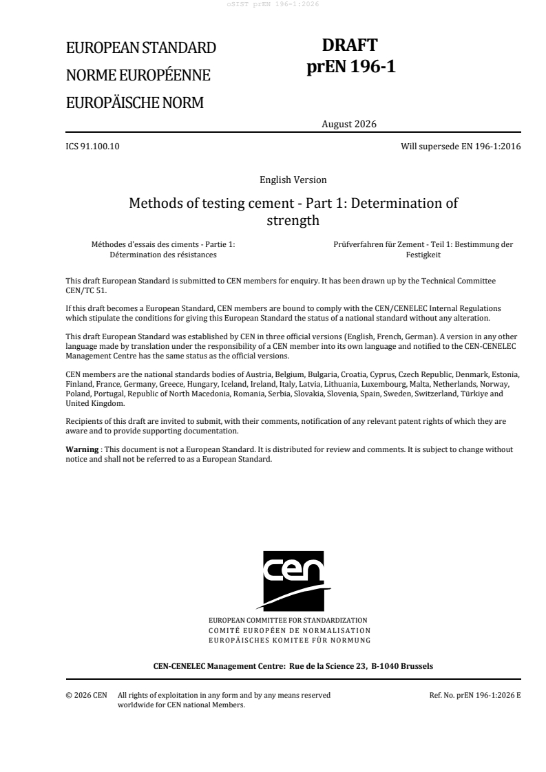
DRAFT
EUROPEAN STANDARD
NORME EUROPÉENNE
EUROPÄISCHE NORM
August 2026
ICS 91.100.10 Will supersede EN 196-1:2016
English Version
Methods of testing cement - Part 1: Determination of
strength
Méthodes d'essais des ciments - Partie 1: Prüfverfahren für Zement - Teil 1: Bestimmung der
Détermination des résistances Festigkeit
This draft European Standard is submitted to CEN members for enquiry. It has been drawn up by the Technical Committee
CEN/TC 51.
If this draft becomes a European Standard, CEN members are bound to comply with the CEN/CENELEC Internal Regulations
which stipulate the conditions for giving this European Standard the status of a national standard without any alteration.
This draft European Standard was established by CEN in three official versions (English, French, German). A version in any other
language made by translation under the responsibility of a CEN member into its own language and notified to the CEN-CENELEC
Management Centre has the same status as the official versions.
CEN members are the national standards bodies of Austria, Belgium, Bulgaria, Croatia, Cyprus, Czech Republic, Denmark, Estonia,
Finland, France, Germany, Greece, Hungary, Iceland, Ireland, Italy, Latvia, Lithuania, Luxembourg, Malta, Netherlands, Norway,
Poland, Portugal, Republic of North Macedonia, Romania, Serbia, Slovakia, Slovenia, Spain, Sweden, Switzerland, Türkiye and
United Kingdom.
Recipients of this draft are invited to submit, with their comments, notification of any relevant patent rights of which they are
aware and to provide supporting documentation.
Warning : This document is not a European Standard. It is distributed for review and comments. It is subject to change without
notice and shall not be referred to as a European Standard.
EUROPEAN COMMITTEE FOR STANDARDIZATION
COMITÉ EUROPÉEN DE NORMALISATION
EUROPÄISCHES KOMITEE FÜR NORMUNG
CEN-CENELEC Management Centre: Rue de la Science 23, B-1040 Brussels
© 2026 CEN All rights of exploitation in any form and by any means reserved Ref. No. prEN 196-1:2026 E
worldwide for CEN national Members.
Page
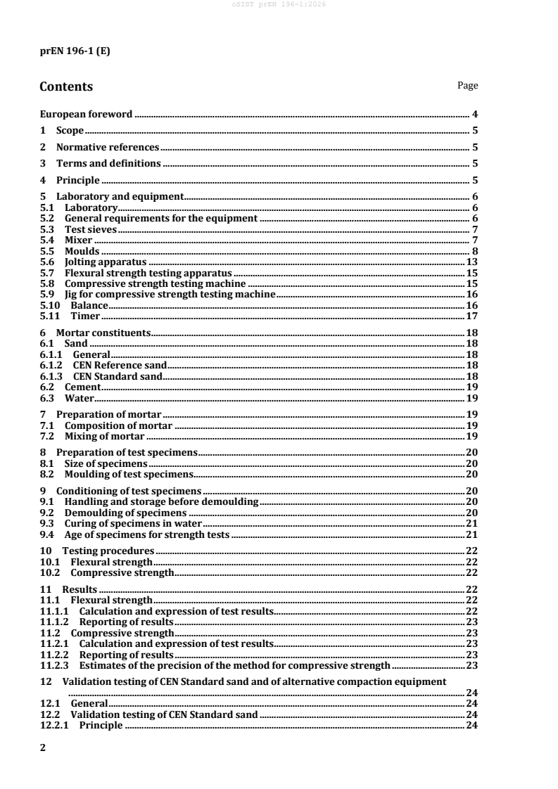
Contents
European foreword . 4
1 Scope . 5
2 Normative references . 5
3 Terms and definitions . 5
4 Principle . 5
5 Laboratory and equipment . 6
5.1 Laboratory. 6
5.2 General requirements for the equipment . 6
5.3 Test sieves . 7
5.4 Mixer . 7
5.5 Moulds . 8
5.6 Jolting apparatus . 13
5.7 Flexural strength testing apparatus . 15
5.8 Compressive strength testing machine . 15
5.9 Jig for compressive strength testing machine . 16
5.10 Balance . 16
5.11 Timer . 17
6 Mortar constituents . 18
6.1 Sand . 18
6.1.1 General . 18
6.1.2 CEN Reference sand . 18
6.1.3 CEN Standard sand . 18
6.2 Cement . 19
6.3 Water . 19
7 Preparation of mortar . 19
7.1 Composition of mortar . 19
7.2 Mixing of mortar . 19
8 Preparation of test specimens . 20
8.1 Size of specimens . 20
8.2 Moulding of test specimens . 20
9 Conditioning of test specimens . 20
9.1 Handling and storage before demoulding . 20
9.2 Demoulding of specimens . 20
9.3 Curing of specimens in water . 21
9.4 Age of specimens for strength tests . 21
10 Testing procedures . 22
10.1 Flexural strength . 22
10.2 Compressive strength . 22
11 Results . 22
11.1 Flexural strength . 22
11.1.1 Calculation and expression of test results. 22
11.1.2 Reporting of results . 23
11.2 Compressive strength . 23
11.2.1 Calculation and expression of test results. 23
11.2.2 Reporting of results . 23
11.2.3 Estimates of the precision of the method for compressive strength . 23
12 Validation testing of CEN Standard sand and of alternative compaction equipment
........................................................................................................................................................................ 24
12.1 General . 24
12.2 Validation testing of CEN Standard sand . 24
12.2.1 Principle . 24
12.2.2 Certification testing of CEN Standard sand . 25
12.2.3 Method of certification testing . 26
12.2.4 Verification testing of CEN Standard sand . 27
12.2.5 Method of verification testing of CEN Standard sand . 27
12.3 Validation testing of alternative compaction equipment . 28
12.3.1 General requirements . 28
12.3.2 Method of testing of alternative compaction equipment . 28
Annex A (normative) Alternative vibration compaction equipment and procedures
validated as equivalent to the reference jolting compaction equipment and
procedure . 30
A.1 General . 30
A.2 Vibrating table, A . 30
A.2.1 Technical description . 30
A.2.2 Compaction procedure using vibrating table, A . 31
A.3 Vibrating table, B . 33
A.3.1 Technical description . 33
A.3.2 Compaction procedure using vibrating table, B . 34
Bibliography . 36
European foreword
This document (prEN 196-1:2026) has been prepared by Technical Committee CEN/TC 51"Cement and
building limes", the secretariat of which is held by NBN.
This document is currently submitted to the CEN Enquiry.
This document will supersede EN 196-1:2016.
EN 196-1:2026 includes the following significant technical changes with respect to EN 196-1:2016:
— procedure for adding water to the containers, "Curing of specimens in water" (9.3).
— in 12.2.2.1, the inclusion of limits for clay content and water-soluble chloride in the standard sand
during Initial Certification Testing.
1 Scope
This document specifies the equipment and procedure for the preparation and curing of a standard
mortar to be used for the determination of the compressive and flexural strength of a common cement
in accordance with EN 197-1.
The determination of compressive or flexural strength can be carried out at different curing ages.
The document also describes an alternative method for the compaction of the standard mortar, which
can be considered equivalent.
In addition, the document specifies the characteristics of a CEN reference sand and the minimum
requirement and the acceptance procedure for the CEN standard sand.
In the case of a dispute, only the reference methods or reference sand can be used.
The same equipment and procedures can be used for other types of cement or materials; in some cases,
modifications to the procedure are also permitted, provided that this standard and/or the modifications
are referenced in the relevant product standards.
2 Normative references
The following documents are referred to in the text in such a way that some or all of their content
constitutes requirements of this document. For dated references, only the edition cited applies. For
undated references, the latest edition of the referenced document (including any amendments) applies.
EN 196-7, Methods of testing cement — Methods of taking and preparing samples of cement
EN 197-1, Cement — Part 1: Composition, specifications and conformity criteria for common cements
EN 1744-1, Tests for chemical properties properties of aggregates - Part 9: Chemical analysis
EN ISO 1302, Geometrical Product Specifications (GPS) — Indication of surface texture in technical
product documentation (ISO 1302:2002)
EN ISO 7500-1, Metallic materials — Verification of static uniaxial testing machines — Part 1:
Tension/compression testing machines - Verification and calibration of the force-measuring system (ISO
7500-1:2004)
ISO 565, Test sieves — Metal wire cloth, perforated metal plate and electroformed sheet — Nominal sizes
of openings
ISO 1101, Geometrical Product Specifications (GPS) — Geometrical tolerancing — Tolerances of form,
orientation, location and run-out
ISO 3310-1, Test sieves — Technical requirements and testing — Part 1: Test sieves of metal wire cloth
ISO 4200, Plain end steel tubes, welded and seamless; general tables of dimensions and masses per unit
length
3 Terms and definitions
No terms and definitions are listed in this document.
4 Principle
The method comprises the determination of the compressive, and optionally the flexural, strength of
prismatic test specimens 40 mm × 40 mm × 160 mm in size.
These specimens are cast from a batch of plastic mortar containing one part by mass of cement, three
parts by mass of CEN Standard sand and one half part of water (water/cement ratio 0,50). CEN Standard
sands from various sources and countries may be used provided that they have been shown to give
cement strength results which do not differ significantly from those obtained using the CEN Reference
sand (see Clause 11).
In the reference procedure the mortar is prepared by mechanical mixing and is compacted in a mould
using a jolting apparatus. Alternative compaction equipment and procedures may be used provided that
they have been shown to give cement strength results which do not differ significantly from those
obtained using the reference jolting apparatus and procedure (see Clause 11 and Annex A ).
The specimens are stored in the mould in a moist atmosphere for 24 h and, after demoulding, specimens
are stored under water until strength testing.
At the required age, the specimens are taken from their wet storage, broken in flexure, determining the
flexural strength where required, or broken using other suitable means which do not subject the prism
halves to harmful stresses, and each half tested for strength in compression.
5 Laboratory and equipment
5.1 Laboratory
The laboratory where preparation of specimens takes place shall be maintained at a temperature of (20
± 2) °C and a relative humidity of not less than 50 %.
The moist air room or the large cabinet for storage of the specimens in the mould shall be maintained at
a temperature of (20,0 ± 1,0) °C and a relative humidity of not less than 90 %.
NOTE 1 If the moulds are stored in a cabinet and sealed with grease, preventing any evaporation, it is
sufficient to store an open water reservoir in the basement of the cabinet.
NOTE 2 The cabinet is a lockable cupboard or box in which the moulds are stored; it is usually kept closed
and only opened for storing or removing moulds
The storage containers for curing the specimens in water, and the grates with which they are fitted, shall
be of material which does not react with cement. The temperature of the water shall be maintained at
(20,0 ± 1,0) °C.
The temperature and relative humidity of the air in the laboratory and the temperature of the water in
the storage containers shall be recorded at least once a day during working hours. The temperature and
relative humidity of the moist air room or cabinet shall be recorded at least every 4 h.
Cement, CEN Standard sand (see 6.1.3), water and apparatus used to make and test specimens shall be
at a temperature of (20 ± 2) °C.
Where temperature ranges are given, the target temperature at which the controls are set shall be the
middle value of the range.
5.2 General requirements for the equipment
The tolerances shown in Figure 1 to Figure 5 are important for correct operation of the equipment in
the testing procedure. When regular control measurements show that the tolerances are not met, the
equipment shall be rejected, adjusted or repaired. Records of control measurements shall be kept.
Acceptance measurements on new equipment shall cover mass, volume, and dimensions to the extent
that these are indicated in this document paying particular attention to those critical dimensions for
which tolerances are specified.
In those cases where the material of the equipment can influence the results, the material is specified
and shall be used.
The approximate dimensions shown in the figures are provided as guidance to equipment
manufacturers or operators. Dimensions, which include tolerances, are obligatory.
5.3 Test sieves
Wire cloth test sieves conforming to ISO 3310-1 shall be of the sizes from ISO 565 given in Table 1 (series
R 20).
Table 1 — Aperture of test sieves
Square mesh size (mm)
2,00 1,60 1,00 0,50 0,16 0,08
5.4 Mixer
The mixer shall consist essentially of:
1) a stainless steel bowl with a capacity of about 5 l of the typical shape and size shown in Figure 1,
provided with means by which it can be fixed securely to the mixer frame during mixing and by
which the height of the bowl in relation to the blade and, to some extent, the gap between blade
and bowl can be finely adjusted and fixed;
2) a stainless steel blade of the typical shape, size and tolerances shown in Figure 1, revolving about
its own axis as it is driven in a planetary movement around the axis of the bowl at controlled
speeds by an electric motor. The two directions of rotation shall be opposite and the ratio between
the two speeds shall not be a whole number.
Blades and bowls shall form sets which shall always be used together.
The gap of (3 ± 1) mm refers to the situation when the blade in the empty bowl shown in Figure 1 is
brought as close as possible to the wall. This gap shall be checked regularly applying minimal pressure
to the blade and assuring that there is no perceptible clearance between the joint of the blade and the
axis of the motor.
NOTE 1 Simple tolerance gauges (feeler gauges) are useful where direct measurement is difficult.
NOTE 2 The dimensions marked as approximate on Figure 1 are for the guidance of manufacturers.
The mixer shall operate at the speeds given in Table 2 when mixing the mortar.
Table 2 — Speeds of mixer blade
Rotation around its own axis Planetary movement
-1 –1
min min
Low speed 140 ± 5 62 ± 5
High speed 285 ± 10 125 ± 10
Key
1 bowl
2 blade
Figure 1 — Typical bowl and blade
5.5 Moulds
The mould shall consist of three horizontal compartments so that three prismatic specimens
40 mm × 40 mm in cross section and 160 mm in length can be prepared simultaneously.
A typical design is shown in Figure 2.
The mould shall be made of steel with walls approximately 10 mm thick. Each internal side face of the
mould shall be case hardened to a Vickers hardness of at least HV 200, as supplied.
A minimum Vickers hardness value of HV 400 is recommended.
The mould shall be constructed in such a manner as to facilitate the removal of moulded specimens
without damage. Each mould shall be provided with a machined steel or cast iron baseplate. The mould,
when assembled, shall be positively and rigidly held together and fixed to the baseplate.
The assembly shall be such that there is no distortion or visible leakage during operation. The baseplate
shall make adequate contact with the table of the compacting apparatus and be rigid enough not to
induce secondary vibrations.
NOTE 1 Moulds and jolting apparatus from different manufacturers can have unrelated external dimensions
and masses, so their compatibility needs to be ensured by the purchaser.
Each part of the mould shall be stamped with identifying marks to facilitate assembly and to ensure
conformity to the specified tolerances. Similar parts of separate mould assemblies shall not be
interchanged.
The assembled mould shall conform to the following requirements.
a) The internal dimensions and tolerances of each mould compartment shall be as follows:
length: (160 ± 1) mm;
width: (40,0 ± 0,2) mm;
depth: (40,1 ± 0,1) mm.
b) The flatness tolerance (see ISO 1101) over the whole of each internal side face shall be not greater
than 0,03 mm.
c) The perpendicularity tolerance (see ISO 1101) for each internal face with respect to the bottom
surface of the mould and the adjacent internal face as datum faces shall be not greater than
0,2 mm.
d) The surface texture (see EN ISO 1302) of each internal side face shall be not rougher than N8, as
supplied.
Moulds shall be replaced when any one of the specified tolerances is exceeded. The mass of the mould
shall accord with the requirement for the combined mass in 5.6.
In preparing the cleaned mould ready for use, a suitable sealing material shall be used to coat the outer
joints of the mould. A thin film of mould oil shall be applied to the internal faces of the mould.
NOTE 2 Some oils have been found to affect the setting of cement; mineral-based oils have been found to be
suitable.
To facilitate the filling of the mould a tightly fitting metal hopper with vertical walls 20 mm to 40 mm in
height shall be provided. When viewed in plan, the hopper walls shall overlap the internal walls of the
mould by not more than 1 mm. The outer walls of the hopper shall be provided with a means of location
to ensure correct positioning over the mould.
For spreading and striking off the mortar two spreaders and a metal straight-edge of the type shown in
Figure 3 shall be provided.
Key
1 striking off direction with sawing motion
Figure 2 — Typical mould
a) Large spreader
b) Small spreader
c) Straight-edge
Key
D height of hopper
Figure 3 — Typical spreaders and metal straight-edge
5.6 Jolting apparatus
The jolting apparatus (a typical design is shown in Figure 4) shall conform to the following
requirements.
The apparatus shall consist of a rectangular table rigidly connected by two light arms to a pivot at
nominally 800 mm from the centre of the table. The table shall incorporate at the centre of its lower face
a projecting lug with a rounded face. Beneath the projecting lug shall be a small stop with a plane upper
surface. In the rest position, the common normal through the point of contact of the lug and the stop
shall be vertical. When the lug rests on the stop, the top face of the table shall be horizontal so that the
level of any of the four corners does not deviate from the mean level by more than 1,0 mm. The table
shall have dimensions equal to or greater than those of the mould baseplate, and a plane machined
upper surface. Clamps shall be provided for firm attachment of the mould to the table.
The combined mass of the table, including arms, empty mould, hopper and clamps shall be (20,0 ± 0,5)
kg.
The arms connecting the table assembly to the pivot shall be rigid and constructed of round tubing with
an outside diameter lying in the range 17 mm to 22 mm selected from tube sizes given in ISO 4200. The
total mass of the two arms, including any cross bracing, shall be (2,25 ± 0,25) kg. The pivot bearings
shall be of the ball or roller type and protected from ingress of grit or dust. The horizontal displacement
of the centre of the table as caused by the play of the pivot shall not exceed 1,0 mm.
The lug and the stop shall be made of through-hardened steel of at least HV 500 Vickers hardness value.
-1
The curvature of the lug shall be about 0,01 mm .
In operation, the table is raised by a cam and allowed to fall freely from a height of (15,0 ± 0,3) mm
before the lug strikes the stop.
The cam shall be made of through hardened steel of at least HV 400 Vickers hardness value and its shaft
shall be mounted in ball bearings of such construction that the free fall is always (15,0 ± 0,3) mm. The
cam follower shall be of a construction which ensures minimal wear of the cam. The cam shall be driven
by an electric motor of about 250 W through a reduction gear at a uniform speed of one revolution per
second. A control mechanism and a counter shall be provided which ensures that one period of jolting
of (60 ± 3) s comprises exactly 60 jolts.
The position of the mould on the table shall be such that the longitudinal dimension of the compartments
is in line with the direction of the arms and perpendicular to the axis of rotation of the cam. Suitable
reference marks shall be provided to facilitate the positioning of the mould in such a way that the centre
of the central compartment is directly above the point of impact.
The apparatus shall be firmly mounted on a concrete block of mass of about 600 kg and volume of about
0,25 m and of dimensions giving a suitable working height for the mould. The entire base of the concrete
block shall stand on an elastic pad, e.g. natural rubber, having a suitable isolation efficiency preventing
external vibrations from affecting the compaction.
The base of the apparatus shall be fixed level to the concrete base by anchor bolts and a thin layer of
mortar shall be placed between the base of the apparatus and the concrete base to ensure overall and
vibration free contact.
The base of the apparatus shall be fixed level to the concrete base by anchor bolts to ensure overall and
vibration free contact.
Key
1 lug
2 cam follower
3 cam
4 stop
Figure 4 — Typical jolting apparatus
5.7 Flexural strength testing apparatus
NOTE The provision of this apparatus is optional. If only the compressive strength is to be measured, prisms
can be broken using other suitable means which do not subject the prism halves to harmful stresses.
The flexural strength can be measured by using a flexural strength testing machine or by using a suitable
device in a compression testing machine. In either case, the apparatus shall conform to the following
requirements:
The apparatus for the determination of flexural strength shall be capable of applying loads up to 10 kN
with an accuracy of ± 1,0 % of the recorded load in the upper four-fifths of the range being used, at a
rate of loading of (50 ± 10) N/s.
The apparatus shall be provided with a flexure device incorporating two steel supporting rollers of
(10,0 ± 0,5) mm diameter spaced (100,0 ± 0,5) mm apart and a third steel loading roller of the same
diameter placed centrally between the other two. The length of these rollers shall be between 45 mm
and 50 mm. The loading arrangement is shown in Figure 5.
a) Front view
b) Side view
Figure 5 — Arrangement of loading for determination of flexural strength
The three vertical planes through the axes of the three rollers shall be parallel and remain parallel,
equidistant and normal to the direction of the specimen under test. One of the supporting rollers and
the loading roller shall be capable of tilting slightly to allow a uniform distribution of the load over the
width of the specimen without subjecting it to any torsional stresses.
5.8 Compressive strength testing machine
The testing machine for the determination of compressive strength shall be of suitable capacity for the
test (see Note 1): it shall have an accuracy of ± 1,0 % of the recorded load in the upper four-fifths of the
range being used when verified in accordance with EN ISO 7500-1. It shall provide a rate of load increase
of (2 400 ± 200) N/s. It shall be fitted with an indicating device which shall be so constructed that the
value indicated at failure of the specimen remains indicated after the testing machine is unloaded. This
can be achieved by the use of a maximum indicator on a pressure gauge or a memory on a digital display.
Manually operated testing machines shall be fitted with a pacing device to facilitate the control of the
load increase.
The vertical axis of the ram shall coincide with the vertical axis of the machine and during loading the
direction of movement of the ram shall be along the vertical axis of the machine. Furthermore, the
resultant of the forces shall pass through the centre of the specimen. The surface of the lower machine
platen shall be normal to the axis of the machine and remain normal during loading.
The centre of the upper platen spherical seating shall be at the point of intersection of the vertical
machine axis with the plane of the lower surface of the upper machine platen with a tolerance of ± 1 mm.
The upper platen shall be free to align as contact is made with the specimen, but during loading the
relative attitude of the upper and lower platens shall remain fixed.
The testing machine shall be provided with platens made of tungsten carbide, or alternatively through
hardened steel with a Vickers hardness of at least HV 600. These platens shall be at least 10 mm thick,
(40,0 ± 0,1) mm wide and (40,0 ± 0,1) mm long. The flatness tolerance according to ISO 1101, over the
entire contact surface with the specimen shall be not greater than 0,01 mm. The surface texture
according to EN ISO 1302 shall be not smoother than N3 and not rougher than N6, as supplied.
Alternatively, two auxiliary plates of tungsten carbide, or through hardened steel with a Vickers
hardness of at least HV 600 and at least 10 mm thick and conforming to the requirements for the platens
may be provided. Provision should be made for centring the auxiliary plates with respect to the axis of
the loading system with an accuracy of ± 0,5 mm or 0,2 mm. Provision should be made for aligning the
auxiliary plates with a tolerance not greater than ± 0,5 mm from the centre of each other.
Where there is no spherical seating in the testing machine or where the spherical seating is blocked, or
where the diameter of the spherical seating is greater than 120 mm, a jig conforming to 5.9 shall be used.
NOTE 1 The testing machine can be provided with two or more load ranges. The highest value of the lower
range would be approximately 1/5 of the highest value of the next higher range.
NOTE 2 The machine would be provided with an automatic method for adjusting the rate of loading and with
equipment for recording the results.
NOTE 3 The spherical seating of the machine can be lubricated to facilitate adjustment on contact with the
specimen but only to such an extent that movement of the platen cannot take place under load during the test.
Lubricants which are effective under high pressure are not suitable.
The terms 'vertical', 'lower' and 'upper' refer to conventional testing machines which are normally
aligned in the vertical axis. However, machines whose axis is not vertical are also permitted.
5.9 Jig for compressive strength testing machine
When 5.8 requires the use of a jig (see Figure 6), it shall be placed between the platens of the machine
to transmit the load of the machine to the compression surfaces of the mortar specimen.
A lower plate shall be used in this jig and it can be incorporated in the lower platen. The upper platen
receives the load from the upper platen of the machine through an intermediate spherical seating. This
seating forms part of an assembly which shall be able to slide vertically without appreciable friction in
the jig guiding its movement. The jig shall be kept clean and the spherical seating shall be free to move
in such a way that the platen will accommodate itself initially to the shape of the specimen and then
remain fixed during the test. All requirements stated in 5.8 apply equally when a jig is used.
NOTE 1 The spherical seating of the jig can be lubricated but only to such an extent that movement of the
platen cannot take place under load during the test. Lubricants which are effective under high pressure are not
suitable.
NOTE 2 It is desirable that the assembly return automatically to its initial position after crushing the
specimen.
5.10 Balance
Balance, capable of weighing to an accuracy of ± 1 g.
5.11 Timer
Timer, capable of measuring to an accuracy of ± 1 s.
Key
1 ball bearings
2 sliding assemble
3 return spring
4 spherical seating of machine
5 upper platen of machine
6 spherical seating of the jig
7 upper platen of the jig
8 specimen
9 lower platen of the jig
10 jig
11 lower platen of the machine
Figure 6 — Typical jig for compressive strength testing
6 Mortar constituents
6.1 Sand
6.1.1 General
CEN standard sands shall be used to determine the strength of cement in accordance with this
document.
NOTE CEN standard sands are produced in various European countries.
CEN standard sand, as specified in this document, shall conform to the requirements given in 6.1.3.
Producers of CEN standard sand shall carry out verification testing under the authority of an accredited
certification body.
CEN standard sands shall be validated against the CEN reference sand described in 6.1.2, by means of
certification and verification testing as specified in 12.2.
6.1.2 CEN Reference sand
The CEN reference sand, of which a limited stockpile is maintained as reference material by the
producer, is a natural siliceous sand consisting of rounded particles and has a silica content of at least
98 %.
Its particle size distribution lies within the limits given in Table 3.
Table 3 — Particle size distribution of the CEN reference sand
Square
mesh size 2,00 1,60 1,00 0,50 0,16 0,08
(mm)
Cumulative
sieve 0 7 ± 5 33 ± 5 67 ± 5 87 ± 5 99 ± 1
residue (%)
NOTE Information on the CEN Reference sand can be obtained from Normensand GmbH, D-59269 Beckum,
Germany.
6.1.3 CEN Standard sand
CEN Standard sand shall comply with the particle size distribution specified in 6.1.2 as determined by
sieve analysis on a representative sample of sand of total mass not less than 1 345 g. Sieving shall be
continued until the amount of sand passing through each sieve is less than 0,5 g/min.
The moisture content shall be less than 0,2 % determined as the loss of mass of a representative sample
of sand after drying at 105 °C to 110 °C to constant mass and expressed as a percentage by mass of the
dried sample.
During production these determinations shall be carried out at least once a day.
These requirements are insufficient to ensure that the CEN Standard sand gives equivalent performance
to the CEN Reference sand. Such equivalence shall be initiated and maintained by the validation testing
described in Clause 12 .
CEN Standard sand shall be pre-packed in bags with a content of (1 350 ± 5) g; the type of material used
for the bags shall have no effect on the results of the strength testing and the contents of each bag shall
comply with the particle size distribution specified in 6.1.2.
CEN Standard sand shall be carefully stored to prevent damage or contamination, particularly with
moisture, prior to use.
6.2 Cement
The cement to be tested shall be exposed to ambient air for the minimum time possible. When it is to be
kept for more than 24 h between sampling and testing, it shall be stored in completely filled and airtight
containers made from a material which does not react with cement.
The laboratory sample shall be homogenized, by machine or other means as described in EN 196-7,
before taking sub-samples for testing.
6.3 Water
Distilled, or deionized, water shall be used for validation testing. For other tests, drinking water can be
used. In the case of dispute, distilled or deionized water shall be used.
7 Preparation of mortar
7.1 Composition of mortar
The proportions by mass shall be one part of the cement (6.2), three parts of CEN Standard sand (6.1),
and one-half part of water (6.3) (water/cement ratio 0,50).
Each batch for three test specimens shall consist of (450 ± 2) g of cement, (1 350 ± 5) g of sand and (225
± 1) g of water.
7.2 Mixing of mortar
Weigh the cement and water by means of the balance (5.10). When water is added by volume it shall be
dispensed with an accuracy of ± 1 ml. Mix each batch of mortar mechanically using the mixer (5.4). The
timing of the various mixing stages refers to the times at which mixer power is switched on/off and shall
be maintained within ± 2 s.
The mixing procedure shall be as follows:
a) place the water and the cement into the bowl, taking care to avoid loss of water or cement;
addition shall be completed within 30 s;
b) immediately the water and cement are brought into contact, start the mixer at the low speed (see
Table 2) whilst starting the timing of the mixing stages. In addition, record the time to the nearest
minute, as ‘zero time’. After 30 s of mixing, add the sand steadily during the next 30 s. Switch the
mixer to the high speed (see Table 2) and continue the mixing for an additional 30 s.
NOTE 1 ‘Zero time’ is the point from which the times for demoulding specimens (see 9.2) and for determining
strength (see 9.4) are calculated.
c) stop the mixer for 90 s. During the first 30 s, remove by means of a rubber or plastics scraper the
mortar adhering to the wall and bottom part of the bowl and place in the middle of the bowl.
d) continue the mixing at the high speed for 60 s.
NOTE 2 Normally these mixing operations are carried out automatically. Manual control of these operations
and timings can be used.
8 Preparation of test specimens
8.1 Size of specimens
The test specimens shall be 40 mm × 40 mm × 160 mm prisms.
8.2 Moulding of test specimens
Mould the specimens immediately after the preparation of the mortar. With the mould and hopper
firmly clamped to the jolting table, introduce, using a suitable scoop, in one or more increments, the first
of two layers of mortar (each about 300 g) into each of the mould compartments, directly from the
mixing bowl.
Introduce the second layer of mortar, ensuring that there is a surplus of mortar, level with the small
spreader (see Figure 3) which is drawn forwards and backwards once and compact.
Spread the layer uniformly using the large spreader (see Figure 3), held almost vertically with its
shoulders in contact with the top of the hopper and drawn forwards and backwards once along each
mould compartment. Then compact the first mortar layer using 60 jolts of the jolting apparatus (5.6).
Introduce the second layer of mortar, ensuring that there is a surplus of mortar, level with the small
spreader (see Figure 3) and compact the layer with a further 60 jolts.
Lift the mould gently from the jolting table and remove the hopper. Immediately strike off the excess
mortar with the metal straight-edge (see Figure 3), held almost vertically but inclined in the direction
of striking. Move slowly pulling with a transverse sawing motion, without pressing hard, once in each
direction. Repeat this striking off procedure with the straight-edge held at a more acute angle to smooth
the surface.
NOTE The number of sawing motions and the angle of the straight-edge will depend on the consistency of
the mortar; stiffer mortars will need more sawing motions and a more acute angle; a smaller number of transverse
sawing motions are needed for smoothing than for striking off (see Figure 2).
Wipe off the mortar left on the perimeter of the mould as a result of the striking-off.
Label or mark the moulds for identification purposes.
9 Conditioning of test specimens
9.1 Handling and storage before demoulding
Place a plate of glass or other impermeable material such as steel or acrylic glass (PMMA) which does
not react with the cement of approximate size 210 mm x 185 mm x 6 mm
...