


oSIST prEN IEC 60255-167:2026
(Main)Measuring relays and protection equipment - Part 167: Functional requirements for directional overcurrent protection
General Information
- Abstract
- Status
- Not Published
- Public Enquiry End Date
- 31-Oct-2026
- Technical Committee
- ISS EIT.ERE - All-or-nothing electrical relays
- Current Stage
- 4020 - Public enquire (PE) (Adopted Project)
- Start Date
- 02-Sep-2026
- Due Date
- 20-Jan-2027

Overview
oSIST prEN IEC 60255-167:2026 – Measuring relays and protection equipment – Part 167: Functional requirements for directional overcurrent protection – is an international draft standard developed under the auspices of the Slovenian Institute for Standardization (SIST) and IEC TC 95. This standard defines the essential functional and performance requirements for directional overcurrent protection functions in electrical protection systems, specifically focusing on the directional element.
Directional overcurrent protection plays a key role in electricity transmission and distribution by enabling targeted fault detection based on current direction and magnitude. This standard specifies the technical features, performance criteria, and test methodologies for directional overcurrent relays and related protection equipment, supporting safer and more reliable energy systems.
Key Topics
- Scope of Directional Overcurrent Protection: Defines minimum functional and performance requirements for directional overcurrent protection applied to various scenarios, including phase, positive-sequence, negative-sequence, zero-sequence, and neutral overcurrent functions.
- Functional Components: Addresses combined operation of an overcurrent element (covered by IEC 60255-151) and a directional element that supervises operation based on fault current direction.
- Technical Definitions: Standardizes key terminologies, such as characteristic and polarizing quantities, operating and effective range, characteristic angle, operate value, reset value, and angular reset hysteresis, ensuring clear communication.
- Performance Specifications:
- Accuracy and dynamic performance requirements for directional elements.
- Performance criteria for operate and disengage time, dynamic response, and resilience to various system conditions.
- Test Methods:
- Standardized procedures for performance and functional testing, including pseudo-continuous ramp and shot ramp methods for evaluating angular accuracy and response.
- Requirements for both type-testing and ongoing product evaluation.
- Documentation Requirements: Mandates detailed type test reports and technical documentation to ensure transparent and verifiable protection function declarations.
- Digital Interfaces: Includes guidance and requirements (Annex B) for directional overcurrent protection functions that use digital communication, referencing standards such as IEC 61850 and related instrument transformer interfaces.
Applications
Directional overcurrent protection per IEC 60255-167 is critical in the following contexts:
- Power System Protection: Ensures selective and reliable tripping in network sections based on fault direction, minimizing system outages and facilitating prompt restoration.
- Electricity Transmission & Distribution: Used in substations, feeders, and ring mains to distinguish between internal and external faults, especially in interconnected networks.
- Integration with Smart Grids: Supports digital substation architectures utilizing communication protocols like IEC 61850 for advanced protection schemes, improved data integration, and operational efficiency.
- Complex Fault Scenarios: Addresses protection for symmetrical and unsymmetrical faults, including single phase, phase-to-phase, phase-to-earth, and evolving faults with dynamic system conditions.
- Industrial and Utility Applications: Applicable for utilities, transmission operators, and industrial facilities seeking standardization and interoperability in their protection equipment.
Related Standards
Implementation and testing of IEC 60255-167 should be coordinated with the following standards:
- IEC 60255-1: General requirements for measuring relays and protection equipment.
- IEC 60255-151: Functional requirements for over/under current protection.
- IEC TS 60255-216-1: General requirements for protection functions using digital communication.
- IEC 61850 Series: Communication networks and systems for power utility automation, covering protocols, logical node definitions, and data object classes.
- IEC 61869 Series: Instrument transformers, including digital interfaces and merging units.
These related documents provide additional guidance to ensure compliant integration, interoperability, and safe use of directional overcurrent protection equipment in modern power systems.
By adhering to oSIST prEN IEC 60255-167:2026, organizations ensure their directional overcurrent protection relays and systems meet globally recognized functional and performance benchmarks, supporting the reliability and resilience of electrical infrastructure in line with the latest international best practices.
Get Certified
Connect with accredited certification bodies for this standard

IMQ S.p.A. (Certification)
Italian electrical product certification.

SLG Prüf- und Zertifizierungs GmbH
German testing and certification body.

UL Solutions
Global safety science company with testing, inspection and certification.
Sponsored listings
Frequently Asked Questions
oSIST prEN IEC 60255-167:2026 is a draft published by the Slovenian Institute for Standardization (SIST). Its full title is "Measuring relays and protection equipment - Part 167: Functional requirements for directional overcurrent protection". This standard covers: Measuring relays and protection equipment - Part 167: Functional requirements for directional overcurrent protection
Measuring relays and protection equipment - Part 167: Functional requirements for directional overcurrent protection
oSIST prEN IEC 60255-167:2026 is classified under the following ICS (International Classification for Standards) categories: 29.120.70 - Relays. The ICS classification helps identify the subject area and facilitates finding related standards.
oSIST prEN IEC 60255-167:2026 is available in PDF format for immediate download after purchase. The document can be added to your cart and obtained through the secure checkout process. Digital delivery ensures instant access to the complete standard document.
Standards Content (Sample)
SLOVENSKI STANDARD
01-oktober-2026
Merilni releji in zaščitna oprema - 167. del: Funkcionalne zahteve za smerno
nadtokovno zaščito
Measuring relays and protection equipment - Part 167: Functional requirements for
directional overcurrent protection
Relais de mesure et dispositifs de protection - Partie 167: Exigences fonctionnelles pour
la protection directionnelle de surintensité
Ta slovenski standard je istoveten z: prEN IEC 60255-167:2026
ICS:
29.120.70 Releji Relays
2003-01.Slovenski inštitut za standardizacijo. Razmnoževanje celote ali delov tega standarda ni dovoljeno.
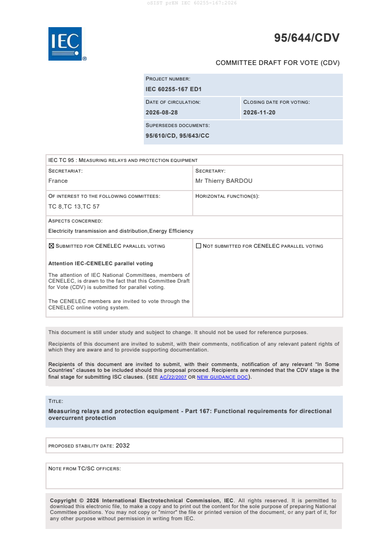
95/644/CDV
COMMITTEE DRAFT FOR VOTE (CDV)
PROJECT NUMBER:
IEC 60255-167 ED1
DATE OF CIRCULATION: CLOSING DATE FOR VOTING:
2026-08-28 2026-11-20
SUPERSEDES DOCUMENTS:
95/610/CD, 95/643/CC
IEC TC 95 : MEASURING RELAYS AND PROTECTION EQUIPMENT
SECRETARIAT: SECRETARY:
France Mr Thierry BARDOU
OF INTEREST TO THE FOLLOWING COMMITTEES: HORIZONTAL FUNCTION(S):
TC 8,TC 13,TC 57
ASPECTS CONCERNED:
Electricity transmission and distribution,Energy Efficiency
SUBMITTED FOR CENELEC PARALLEL VOTING NOT SUBMITTED FOR CENELEC PARALLEL VOTING
Attention IEC-CENELEC parallel voting
The attention of IEC National Committees, members of
CENELEC, is drawn to the fact that this Committee Draft
for Vote (CDV) is submitted for parallel voting.
The CENELEC members are invited to vote through the
CENELEC online voting system.
This document is still under study and subject to change. It should not be used for reference purposes.
Recipients of this document are invited to submit, with their comments, notification of any relevant patent rights of
which they are aware and to provide supporting documentation.
Recipients of this document are invited to submit, with their comments, notification of any relevant “In Some
Countries” clauses to be included should this proposal proceed. Recipients are reminded that the CDV stage is the
final stage for submitting ISC clauses. (SEE AC/22/2007 OR NEW GUIDANCE DOC).
TITLE:
Measuring relays and protection equipment - Part 167: Functional requirements for directional
overcurrent protection
PROPOSED STABILITY DATE: 2032
NOTE FROM TC/SC OFFICERS:
download this electronic file, to make a copy and to print out the content for the sole purpose of preparing National
Committee positions. You may not copy or "mirror" the file or printed version of the document, o r any part of it, for
any other purpose without permission in writing from IEC.
IEC CDV 60255-167 © IEC 2026
Link to Committee Draft for Vote (CDV) online document:
Click here
How to access
This link leads you to the Online Standards Development (OSD) platform for National Mirror
Committee’s (NMC) comments. The project draft may be found further down this document.
Resource materials
We recommend NCs to review the available materials to better understand the member
commenting on the OSD platform. This includes the:
• OSD NC roles overview
• How to add and submit comments to the IEC
Contact
Should you require any assistance, please contact the IEC IT Helpdesk.
IEC CDV 60255-167 © IEC 2026
CONTENTS
CONTENTS . 3
FOREWORD . 7
INTRODUCTION . 9
1 Scope . 10
2 Normative references . 10
3 Terms, definitions and abbreviations . 11
3.1 Terms and definitions. 11
3.2 Symbols and abbreviated terms . 14
4 Specification of directional overcurrent protection function . 15
4.1 General . 15
4.2 Input energizing quantities . 15
4.2.1 General . 15
4.2.2 Connections . 16
4.2.3 Polarizing quantities and operating quantities of directional element . 16
4.3 Binary input signals. 17
4.4 Functional logic . 17
4.4.1 Directional element . 17
4.4.2 Operating logic . 19
4.5 Binary output signals . 19
4.5.1 General . 19
4.5.2 Start (pickup) signals . 19
4.5.3 Operate (trip) signals . 19
4.5.4 Other output signals . 20
4.6 Additional influencing functions and conditions . 20
4.6.1 General . 20
4.6.2 Input energizing quantity failure . 20
4.6.3 Load encroachment . 20
4.7 Instrument transformer requirements . 21
5 Performance specification . 21
5.1 General . 21
5.2 Effective and operating ranges. 21
5.3 Accuracy related to directional element . 22
5.4 Operate time of directional element . 22
5.5 Disengage time of directional element . 22
5.6 Dynamic performance . 22
5.6.1 General . 22
5.6.2 Typical operate time of directional element . 23
5.6.3 Impacts of prefault load and fault resistance . 23
5.6.4 Evolving faults . 23
5.6.5 Current reversal condition . 23
6 Functional tests . 23
6.1 General . 23
6.1.1 Purpose of the tests. 23
6.1.2 Injection of input energizing quantities . 24
6.1.3 Binary outputs to be monitored . 25
6.1.4 Test Settings and configuration . 25
IEC CDV 60255-167 © IEC 2026
6.1.5 Test methods and procedures . 25
6.2 Determination of accuracy related to directional element . 25
6.2.1 General . 25
6.2.2 Angular accuracy of directional element . 26
6.2.3 Reset hysteresis of directional element . 2
6.3 Determination of operate time of directional element . 6
6.4 Determination of disengage time of directional element . 9
6.5 Dynamic performance tests . 12
6.5.1 General . 12
6.5.2 Determination of typical operate time . 14
6.5.3 Impacts of prefault load and fault resistance . 17
6.5.4 Evolving fault tests . 21
6.5.5 Current reversal tests . 22
7 Documentation requirements . 24
7.1 Type test report . 24
7.2 Technical documentation . 24
Annex A (informative) Examples of directional characteristics of directional
overcurrent protection functions. 25
Annex B (normative) Requirements for a directional overcurrent protection function
using digital communication as inputs and outputs. 27
B.1 General . 27
B.2 Requirements . 27
B.2.1 General requirements for digitally interfaced directional overcurrent
protection functions . 27
B.2.2 Specific requirements for digitally interfaced directional overcurrent
protection functions . 28
B.3 Performance requirements . 31
B.4 Functional tests . 31
B.4.1 Injection of input energizing quantities . 31
B.4.2 Tests for nominal conditions of digitally interfaced protection functions. 31
B.4.3 Performance under abnormal SV and GOOSE . 32
B.5 IEC 61850 based settings . 34
Annex C (informative) Ramping methods for testing the angular accuracy . 36
C.1 General . 36
C.2 Pseudo-continuous ramp . 36
C.3 Ramp of shots. 38
C.4 Ramp of shots with binary search algorithm . 40
Annex D (normative) Calculation of mean, median and mode. 43
D.1 Mean . 43
D.2 Median . 43
D.3 Mode . 43
D.4 Example . 43
Annex E (normative) Definition of fault inception angle . 44
Bibliography . 46
Figure 1 – An example of simplified protection functional block diagram . 15
Figure 2 – Example of operating characteristic for a directional element . 18
Figure 3 – Phase angle ramp of operating quantity for angular accuracy test of
directional element . 27
IEC CDV 60255-167 © IEC 2026
Figure 4 – Example test sequence for angular accuracy of directional element . 28
Figure 5 – Phase angle ramp of operating quantity for reset hysteresis test of
directional element . 2
Figure 6 – Example test sequence for reset hysteresis of directional element . 3
Figure 7 – Example test sequence for operate time of directional element . 7
Figure 8 – Example test sequence for Disengage time of directional element. 10
Figure 9 – Single line, double-infeed system . 12
Figure 10 – Double lines, double-infeed system . 13
Figure 11 – Example test sequence for typical operate time . 16
Figure 12 – Fault resistance of phase-to-earth fault . 17
Figure 13 – Fault resistance of phase-to-phase fault . 18
Figure 14 – Fault resistances of phase-to-phase-to-earth fault . 18
Figure 15 – Three-phase fault . 18
Figure 16 – Example test sequence for impacts of prefault load and fault resistance . 19
Figure C.1 – Pseudo-continuous ramp showing phase angle step change and the time
step 37
Figure C.2 – Ramp of shots showing phase angle step change and the time step . 40
Figure C.3 – Ramp of shots with binary search algorithm . 42
Figure E.1 – Graphical definition of fault inception angle . 44
Table 1 – Directional overcurrent protection designations . 10
Table 2 – Example of effective and operating ranges of directional overcurrent
protection function . 21
Table 3 – Settings associated with the directional element for type tests . 26
Table 4 – Operate angle of directional element . 1
Table 5 – Angular accuracy of directional element . 2
Table 6 – Reset angle of directional element . 5
Table 7 – Angular reset hysteresis of directional element. 6
Table 8 – Injected quantities for operate time test . 6
Table 9 – Operate time test results of directional element . 8
Table 10 – Typical operate time for directional element . 9
Table 11 – Injected quantities for disengage time test . 9
Table 12 – Disengage time test results of directional element . 11
Table 13 – Typical disengage time of directional element . 12
Table 14 – Operate time of directional element . 17
Table 15 – Test cases for impacts of prefault load and fault resistance . 19
Table 16 – Test report for impacts of prefault load and fault resistance . 21
Table 17 – Evolving faults at the same fault location . 21
Table 18 – Evolving faults at different locations . 22
Table 19 – Test report for evolving fault tests . 22
Table 20 – Current reversal tests . 23
Table 21 – Test report for current reversal tests. 23
Table A.1 – Examples of directional characteristic . 25
Table B.1 – Requirements for digitally interfaced functions . 27
IEC CDV 60255-167 © IEC 2026
Table B.2 – Specification of the expected behaviour of the directional overcurrent
protection function receiving abnormal SV as energizing quantities . 30
Table B.3 – Performance requirements for digitally interfaced directional overcurrent
protection functions . 31
Table B.4 – Rated primary quantities to be used for functional test of digitally
interfaced directional overcurrent protection functions . 31
Table B.5 – Test requirements for abnormal GOOSE and SV conditions for digitally
interfaced directional overcurrent protection functions . 32
Table B.6 – Test results for abnormal GOOSE and SV conditions for digitally interfaced
directional overcurrent protection functions . 33
Table B.7 – IEC 61850 settings for directional overcurrent protection . 34
Table E.1 – Fault type and reference voltage . 44
IEC CDV 60255-167 © IEC 2026
INTERNATIONAL ELECTROTECHNICAL COMMISSION
____________
Measuring relays and protection equipment -
Part 167: Functional requirements for directional overcurrent protection
FOREWORD
The International Electrotechnical Commission (IEC) is a worldwide organization for
standardization comprising all national electrotechnical committees (IEC National Committees).
The object of IEC is to promote international co-operation on all questions concerning
standardization in the electrical and electronic fields. To this end and in addition to other
activities, IEC publishes International Standards, Technical Specifications, Technical Reports,
Publicly Available Specifications (PAS) and Guides (hereafter referred to as "IEC
Publication(s)"). Their preparation is entrusted to technical committees; any IEC National
Committee interested in the subject dealt with may participate in this preparatory work.
International, governmental and non-governmental organizations liaising with the IEC also
participate in this preparation. IEC collaborates closely with the International Organization for
Standardization (ISO) in accordance with conditions determined by agreement between the two
organizations.
The formal decisions or agreements of IEC on technical matters express, as nearly as possible,
an international consensus of opinion on the relevant subjects since each technical committee
has representation from all interested IEC National Committees.
IEC Publications have the form of recommendations for international use and are accepted by
IEC National Committees in that sense. While all reasonable efforts are made to ensure that
the technical content of IEC Publications is accurate, IEC cannot be held responsible for the
way in which they are used or for any misinterpretation by any end user.
In order to promote international uniformity, IEC National Committees undertake to apply IEC
Publications transparently to the maximum extent possible in their national and regional
publications. Any divergence between any IEC Publication and the corresponding national or
regional publication shall be indicated in the latter.
IEC itself does not provide any attestation of conformity. Independent certification bodies
provide conformity assessment services and, in some areas, access to IEC marks of conformity.
IEC is not responsible for any services carried out by independent certification bodies.
All users should ensure that they have the latest edition of this publication.
No liability shall attach to IEC or its directors, employees, servants or agents including individual
experts and members of its technical committees and IEC National Committees for any personal
injury, property damage or other damage of any nature whatsoever, whether direct or indirect,
or for costs (including legal fees) and expenses arising out of the publication, use of, or reliance
upon, this IEC Publication or any other IEC Publications.
Attention is drawn to the Normative references cited in this publication. Use of the referenced
publications is indispensable for the correct application of this publication.
IEC draws attention to the possibility that the implementation of this document may involve the
use of (a) patent(s). IEC takes no position concerning the evidence, validity or applicability of
any claimed patent rights in respect thereof. As of the date of publication of this document, IEC
had not received notice of (a) patent(s), which may be required to implement this document.
However, implementers are cautioned that this may not represent the latest information, which
IEC CDV 60255-167 © IEC 2026
may be obtained from the patent database available at https://patents.iec.ch. IEC shall not be
held responsible for identifying any or all such patent rights.
IEC 60255-167 has been prepared by IEC technical committee 95: Measuring relays and
protection equipment. It is an International Standard.
This document partially replaces the standard IEC 60255-12:1980 [1] (Directional relays and
power relays with two input energizing quantities) published in 1980. This edition constitutes a
technical revision for the directional overcurrent protection function.
This edition includes the following significant technical changes with respect to the previous
edition:
a) this document is applicable to the directional overcurrent protection function only.
b) operating quantity and polarizing quantity of the directional element are defined.
c) the operating characteristic, the performance of the directional overcurrent protection
function and corresponding test methods are specified in detail.
d) digitally interfaced directional overcurrent protection function is included.
The text of this International Standard is based on the following documents:
Draft Report on voting
95/XX/FDIS 95/XX/RVD
Full information on the voting for its approval can be found in the report on voting indicated in
the above table.
The language used for the development of this International Standard is English.
This document was drafted in accordance with ISO/IEC Directives, Part 2, and developed in
accordance with ISO/IEC Directives, Part 1 and ISO/IEC Directives, IEC Supplement, available
at www.iec.ch/members_experts/refdocs. The main document types developed by IEC are
described in greater detail at www.iec.ch/publications.
The committee has decided that the contents of this document will remain unchanged until the
stability date indicated on the IEC website under webstore.iec.ch in the data related to the
specific document. At this date, the document will be
• reconfirmed,
• withdrawn, or
• revised.
IEC CDV 60255-167 © IEC 2026
INTRODUCTION
This document is part of the IEC 60255-1xx series of functional standards, which functionally
describes protection functions and provides a framework for testing and assessing the
performance of protection functions. It defines various technical features for protection function
whose performance is declared, as well as the corresponding requirements for testing and
reporting the performance.
For the standardized definitions of a protection function technical feature (such as operate time
or start time) and for the standardized testing methods to evaluate it (e.g., test methods for
assessing accuracy using pseudo-continuous ramp or ramp of shots), Clause 5 defines the
standardized technical features of the protection function. Clause 6 and the related annexes
detail how the performance of this technical feature is tested, evaluated, and reported.
In cases where a protection function technical feature is standardized but lacks a standardized
testing method (for example, effective range , operating range , or the procedure to determine
accuracy), Clause 5 defines the technical feature and requires the manufacturer to provide a
report on the performance of this technical feature in a standardized format.
When neither a standardized definition of the technical feature nor a standardized testing
method exists but the document needs to address a particular behaviour or application, Clause
4 offers a general description of the topic. In such cases, the manufacturer is required to provide
a declaration explaining how they address the topic. This is a requirement in a broad sense.
All the declarations and test results from Clause 5 and Clause 6 are expected to be part of the
protection function type tests according to this document. Declarations from Clause 4 are
expected to be included in technical manuals or any other relevant technical documents related
to the protection function. A note in the type test report, confirming that these declarations have
been addressed, is also expected to be available.
Clause 7 provides a comprehensive list of the declarations and tests that are to be included in
the type test report.
Overall, the presence of the term "shall" throughout the document indicates a requirement.
While these requirements do not always relate strictly to the performance, they ensure
transparency and consistency in testing and reporting the functionality. The p erformance
measurement methods specified in this document reflect international consensus and provide
a consistent framework for protection function testing and evaluation throughout the industry.
The mention of "minimum requirements" in this document refers to the standardized technical
features as well as performance measurement methods where consensus has been reached
on their definitions. Protection functions can have additional proprietary technical features not
covered in this document, but their performance is also part of the product’s type tests. As such,
at a minimum, a type test report for the protection function specified in this document is
expected to provide the information to support and validate the declarations.
This document focuses on the directional overcurrent protection function, which is a
combination of a directional element and an overcurrent element. This standard defines the
specific performance characteristics, requirements and testing methods for the directional
element. The requirements and testing methods for the overcurrent element are already
specified in IEC 60255-151. Therefore, full compliance with IEC 60255-151 is a prerequisite for
evaluating the overcurrent element as part of a directional overcurrent protection function.
Users of this document are expected to refer to IEC 60255-151 for the overcurrent element
aspects, making both documents necessary for complete application of the function.
IEC CDV 60255-167 © IEC 2026
1 Scope
This part of IEC 60255 specifies the minimum requirements for functional and performance
evaluation of an a.c. directional overcurrent protection function. This document also defines
how to document and publish performance test results.
The directional overcurrent protection function comprises an overcurrent element combined
with a directional element. The directional element supervises the operation of the overcurrent
element based on the direction of the fault current. This document specifies the requirements
that apply to the directional element, and refers to IEC 60255-151where relevant to the
overcurrent element. This document defines factors that influence the accuracy and dynamic
performance of the directional overcurrent protection function. The test methods for verifying
the declared performance are also included in this document.
This document covers directional phase, positive-sequence, negative-sequence, zero-
sequence, and neutral overcurrent protection functions, as listed in Table 1. Annex A provides
commonly used operating characteristics of these functions.
Table 1 – Directional overcurrent protection designations
Protection function IEEE/ANSI C37.2-2022 [2] IEC 61850-7-
4:2010/AMD1:2020
Applicable Function Numbers
Applicable Logical
Nodes
Directional phase overcurrent protection 67
a
Directional positive-sequence overcurrent 67
PTOC
protection
a
RDIR+PTOC
Directional negative-sequence overcurrent
protection
Directional zero-sequence overcurrent protection 67N a
PTOC
Directional neutral overcurrent protection 67G
a
RDIR+PTOC
ab
PSDE
a
The direction information of protection Logical Nodes can be available in Data Attribute 'dirGeneral' of its Data
Object 'Str', 'Dir' or 'Op'.
b
The Logical Node PSDE can be used for directional earth fault protection in resonant earthed (neutral) system
and isolated neutral system.
Additional restraint or blocking elements may be part of the directional overcurrent protection
function. This document does not specify the functional description of these additional restraint
or blocking elements.
This document does not cover directional elements integrated into other protection functions,
such as distance protection and power protection.
The general requirements for measuring relays and protection equipment are defined in IEC
60255-1. For digitally interfaced directional overcurrent functions via IEC 61850, Annex B
contains the associated requirements based on IEC TS 60255-216-1:2025.
2 Normative references
The following documents are referred to in the text in such a way that some or all of their content
constitutes requirements of this document. For dated references, only the edition cited applies.
For undated references, the latest edition of the referenced document (including any
amendments) applies.
IEC CDV 60255-167 © IEC 2026
IEC 60255-1, Measuring relays and protection equipment - Part 1: Common requirements
IEC 60255-151:2009, Measuring relays and protection equipment - Part 151: Functional
requirements for over/under current protection
IEC 60255-151, Measuring relays and protection equipment - Part 151: Functional requirements
for over/under current protection
IEC TS 60255-216-1:2025, Measuring relays and protection equipment - Part 216-1: Digital
Interface - General Requirements and Tests for Protection Functions using digital
communication as input and output
IEC 61850-7-1:2011/AMD1:2020, Communication networks and systems for power utility
automation - Part 7-1: Basic communication structure - Principles and models
IEC 61850-7-4:2010/AMD1:2020, Communication networks and systems for power utility
automation - Part 7-4: Basic communication structure - Compatible logical node classes and
data object classes
IEC 61850-8-1:2011/AMD1:2020, Communication networks and systems for power utility
automation - Part 8-1: Specific communication service mapping (SCSM) - Mappings to MMS
(ISO 9506-1 and ISO 9506-2) and to ISO/IEC 8802-3
IEC 61850-9-2, Communication networks and systems for power utility automation - Part 9-2:
Specific communication service mapping (SCSM) - Sampled values over ISO/IEC 8802-3
IEC/IEEE 61850-9-3:2016, Communication networks and systems for power utility automation
- Part 9-3: Precision time protocol profile for power utility automation
IEC 61869-9:2016, Instrument transformers - Part 9: Digital interface for instrument
transformers
IEC 61869-9, Instrument transformers - Part 9: Digital interface for instrument transformers
IEC 61869-13, Instrument transformers - Part 13: Stand-alone merging unit (SAMU)
3 Terms, definitions and abbreviations
3.1 Terms and definitions
For the purposes of this document, the following terms and definitions apply.
ISO and IEC maintain terminology databases for use in standardization at the following
addresses:
• IEC Electropedia: available at https://www.electropedia.org/
• ISO Online browsing platform: available at https://www.iso.org/obp
3.1.1
directional overcurrent protection
protection designed to operate only for a fault located in one direction from the installation point,
and when the current as an energizing quantity exceeds a predetermined value for a given time
IEC CDV 60255-167 © IEC 2026
3.1.2
characteristic quantity
electric quantity, or one of its parameters, the name of which characterizes a protection function
and the value of which are the subject of accuracy requirement
[SOURCE: IEC 60050-447:2020 [3], 447-07-01, modified — "measuring relay or protection
equipment" has been replaced with "protection function", and the original examples have been
deleted.]
3.1.3
operating range
interval for which the measuring relay or
protection equipment under specified conditions is able to perform its intended function(s) in
accordance with the specified requirements
Note 1 to entry: When accuracy requirements have to be met, see "effective range (3.1.4) ".
[SOURCE: IEC 60050-447:2020 [3], 447-03-16]
3.1.4
effective range
interval of an input energizing quantity or a characteristic quantity (3.1.2) within which the
accuracy requirements are met
[SOURCE: IEC 60050-447:2020 [3], 447-07-08]
3.1.5
rated value
value of a quantity used for specification purposes, established for a specified set of operating
conditions of a component, device, equipment, or system
[SOURCE: IEC 60050-151:2001 [4] , 151-16-08]
3.1.6
operating quantity
electric quantity, the phase angle of which with respect to the polarizing
quantity (3.1.7) is recognized by the directional element to determine the fault direction
3.1.7
polarizing quantity
electric quantity that provides an angular reference to the directional element to determine the
fault direction
3.1.8
characteristic angle
maximum sensitivity angle
φ
RCA
angle between the phasor representing operating quantity (3.1.6) and the phasor representing
polarizing quantity (3.1.7) at which the directional element achieves maximum sensitivity
3.1.9
operate value
value of the characteristic quantity (3.1.2) at which a protection
function operates
IEC CDV 60255-167 © IEC 2026
[SOURCE: IEC 60050-447:2020 [3], 447-02-10, modified — "measuring relay or protection
equipment" has been replaced with "protection function", and the original figure has been
deleted.]
3.1.10
reset value
value of the characteristic quantity (3.1.2) at which a protection function resets
[SOURCE: IEC 60050-447:2020 [3], 447-02-12, modified — "measuring relay or protection
equipment" has been replaced with "protection function", and the original figure has been
deleted.]
3.1.11
angular reset hysteresis
absolute value of the angle difference between a reset value (3.1.10) and an operate value
(3.1.9) of directional element
3.1.12
zero-sequence current
one of the three symmetrical sequence components which exists
only in an unsymmetrical three-phase system of sinusoidal quantities and which is defined by
the following complex mathematical expression:
𝐼 = (𝐼 + 𝐼 + 𝐼 )
0 𝐿1 𝐿2 𝐿3
where I , I and I are the complex expressions of the phase current phasors
L1 L2 L3
[SOURCE: IEC 60050-448:1995 [5], 448-11-29, modified — "component" has been replaced
with "current" in term and its definition.]
3.1.13
zero-sequence voltage
one of the three symmetrical sequence components which exists
only in an unsymmetrical three-phase system of sinusoidal quantities and which is defined by
the following complex mathematical expression:
𝑈 = (𝑈 + 𝑈 + 𝑈 )
0 𝐿1 𝐿2 𝐿3
where U , U and U are the complex expressions of the phase voltage phasors
L1 L2 L3
[SOURCE: IEC 60050-448:1995 [5], 448-11-29, modified — "component" has been replaced
with "voltage" in term and its definition.]
3.1.14
neutral current
electric current in the neutral conductor of a polyphase line
[SOURCE: IEC 60050-141:2004 [6], 141-03-05]
3.1.15
neutral overcurrent protection
ground overcurrent protection (US)
overcurrent protection in the earthing connection of the neutral of transformers, reactors or
generators
[SOURCE: IEC 60050-448:1995 [5], 448-14-30, modified — "current protection" has been
replaced with "overcurrent protection " in term and its definition.]
IEC CDV 60255-167 © IEC 2026
3.2 Symbols and abbreviated terms
CT Current Transformer
DG Distributed Generation; Dispersed Generation
I Positive-sequence current
I Negative-sequence current
I zero-sequence current
I Feeder zero sequence current , from busbar to a feeder
0feeder
IED Intelligent Electronic Device
Phase currents
I , I , I
L1 L2 L3
I neutral current, from a neutral-to-earth path CT
neu
G Measured value of the characteristic quantity of overcurrent element
GOOSE Generic Object Oriented System Event
G Setting value (start value) of the characteristic quantity of overcurrent element
S
L-E Phase-to-earth Fault
L-L-E Phase-to-phase-to-earth Fault
RMS Root Mean Square
SAMU Stand- Alone Merging Unit
S operating quantity of directional element
OPD
S Minimum magnitude of the operating quantity required for fault direction
OPD_min
determination
S polarizing quantity of directional element
POL
S Minimum magnitude of the polarizing quantity required for fault direction
POL_min
determination
SV Sampled Values
U Positive-sequence voltage
U Negative-sequence voltage
U , zero-sequence voltage
U , U , Positive-sequence voltages (referenced to each phase-to-earth voltage
1(L1) 1(L2)
respectively), or the memory prefault phase-to-earth voltages
U
1(L3)
U , U , U Phase-to-earth voltages
L1 L2 L3
Phase-to-phase voltages
U , U ,
L1 L2 L2 L3
U
L3 L1
VT Voltage Transformer
VTS Voltage Transformer Signal Supervision
σ Declared accuracy of comparator limit angle
φ
φ Comparator limit angle for forward direction, which defines the forward operate
B
boundary of directional element
φ Comparator limit angle for reverse direction, which defines the reverse operate
BR
boundary of directional element
φ Phase angle of operating quantity
OPD
φ characteristic angle
RCA
IEC CDV 60255-167 © IEC 2026
4 Specification of directional overcurrent protection function
4.1 General
Clause 4 lists the minimum features that shall be described in the product documentation of the
directional overcurrent protection function.
The manufacturer shall provide the functional block diagram of the directional overcurrent
protection function implemented. An example of the expected functional block diagram is shown
in Figure 1.
Figure 1 – An example of simplified protection functional block diagram
The overcurrent element is covered by IEC 60255-151. The requirements for the directional
element is specified in this document.
According to the algorithm implemented by the manufacturer, additional features should be
described in the product documentation.
4.2 Input energizing quantities
4.2.1 General
The product documentation shall state the type of input energizing quantities used by the
directional overcurrent protection function. For example:
– single or three-phase current(s): I (, I , I );
L1 L2 L3
– neutral current, from a neutral-to-earth path CT: I ;
neu
– zero-sequence current (I );
– single or three phase-to-earth voltage(s): U (,U , U );
L1 L2 L3
– multiple phase-to-phase voltage(s): U , U , U ;
L1 L2 L2 L3 L3 L1
– zero-sequence voltage(U ) .
Ratings and relevant requirements for input energizing quantities are specified in IEC 60255 -1.
Input energizing quantities can be presented to the directional overcurrent protection either
hardwired from instrument transformers or transmitted as data received over communication
ports using a data communication protocol, such as IEC 61850-9-2 or, more specifically, IEC
61869-9, which is a profile of IEC 61850-9-2. In the latter case, the directional overcurrent
IEC CDV 60255-167 © IEC 2026
protection function is considered as digitally interfaced function. Annex B provides requirements
for a directional overcurrent protection function using IEC 61850 signals as inputs and outputs.
4.
...