


IEC 62561-2:2025
(Main)Lightning protection system components (LPSC) - Part 2: Requirements for conductors and earth electrodes
General Information
- Abstract
IEC 62561-2:2025 specifies the requirements and tests for
- metallic conductors (other than "natural" conductors) that form part of the air-termination and down-conductor systems, and
- metallic earth electrodes that form part of the earth-termination system.
This third edition cancels and replaces the second edition published in 2018. This edition constitutes a technical revision.
This edition includes the following significant technical changes with respect to the previous edition:
a) definitions of new conductor types mentioned in this document have been added;
b) the document has been updated in line with IEC 60068-2-52:2017 on salt mist treatment;
c) the document has been updated in line with ISO 22479:2019 on humid sulphurous atmosphere treatment;
d) a new normative Annex H for material, configuration and cross-sectional area test has been introduced;
e) a new normative Annex I for applicability of previous tests has been introduced.
f) equipotential earth grid has been introduced.
- Status
- Published
- Publication Date
- 29-Sep-2025
- Technical Committee
- TC 81 - Lightning protection
- Drafting Committee
- MT 14 - TC 81/MT 14
- Current Stage
- PPUB - Publication issued
- Start Date
- 30-Sep-2025
- Completion Date
- 03-Oct-2025
Buy Documents
IEC 62561-2:2025 - Lightning protection system components (LPSC) - Part 2: Requirements for conductors and earth electrodes
IEC 62561-2:2025 RLV - Lightning protection system components (LPSC) - Part 2: Requirements for conductors and earth electrodes Released:9/30/2025
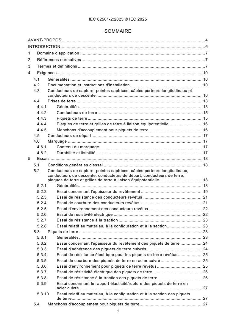
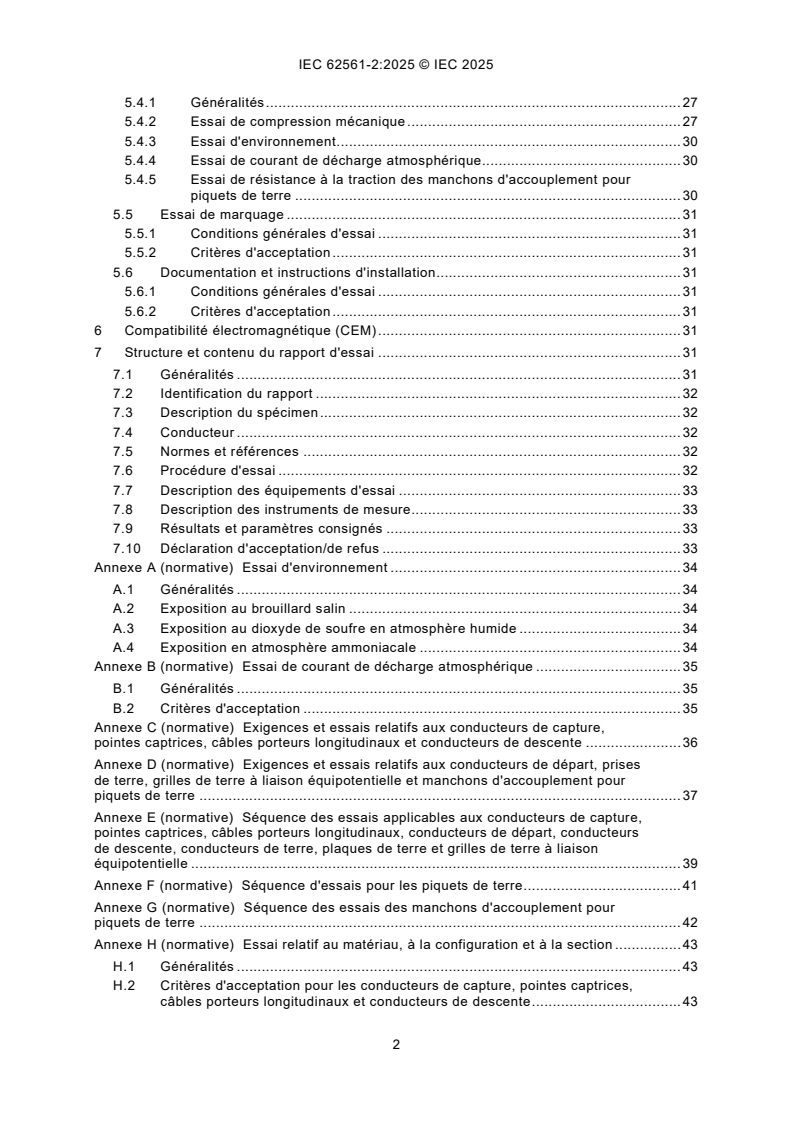
IEC 62561-2:2025 - Composants des systèmes de protection contre la foudre (CSPF) - Partie 2 : Exigences pour les conducteurs et les électrodes de terre
IEC 62561-2:2025 - Lightning protection system components (LPSC) - Part 2: Requirements for conductors and earth electrodes
Overview
IEC 62561-2:2025 is the 2025 third edition of the International Electrotechnical Commission standard for lightning protection system components (LPSC), Part 2: Requirements for conductors and earth electrodes. It specifies mandatory requirements and test methods for metallic conductors (excluding natural conductors) that form part of air‑termination and down‑conductor systems, and for metallic earth electrodes that form part of the earth‑termination system. This edition replaces IEC 62561-2:2018 and introduces several technical updates, including new conductor definitions, updated environmental treatments, and new normative annexes.
Key topics and technical requirements
- Scope and materials: Defines acceptable materials, configuration and cross‑sectional area for air‑termination conductors, catenary wires, down‑conductors, earth lead‑in conductors, earth electrodes and equipotential earth grids.
- Mechanical & electrical characteristics: Requirements for tensile strength, yield/tensile ratio, electrical resistivity and cross‑sectional area.
- Coating and corrosion resistance: Tests for coating thickness, adhesion, and resistance - updated to align with IEC 60068-2-52 (salt mist) and ISO 22479 (humid sulphurous atmosphere). Ammonia atmosphere treatment is also referenced.
- Environmental testing: Normative environmental tests (Annex A) covering salt mist, humid sulphurous and ammonia exposures to assess long‑term durability.
- Lightning current and electrical tests: Lightning impulse/current tests and acceptance criteria (Annex B) for conductors, earth rods and couplers.
- Couplers and connectors: Mechanical compression, environmental and lightning current tests for couplers used with earth rods.
- New normative annexes: Annex H (material, configuration and cross‑sectional area test) and Annex I (applicability of previous tests) clarify test scope and legacy compliance.
- Marking, documentation and EMC: Requirements for durable marking, installation instructions and electromagnetic compatibility considerations; detailed test report structure.
Practical applications and who uses it
- Manufacturers of lightning conductors, earth rods, couplers and equipotential earth grids use the standard to design and certify products.
- Testing laboratories and certification bodies apply the specified tests and report formats for product compliance.
- Electrical and lightning protection engineers / specifiers reference the standard when designing air‑termination, down‑conductor and earth‑termination systems.
- Installers and contractors rely on the documented installation instructions and marking requirements to ensure compliant on‑site implementation.
- Asset owners and safety auditors use the standard to verify that lightning protection components meet internationally accepted durability and performance criteria.
Related standards
- IEC 62561 series (other parts of the LPSC family)
- IEC 60068-2-52 (salt mist treatment)
- ISO 22479 (humid sulphurous atmosphere treatment)
Keywords: IEC 62561-2:2025, lightning protection, conductors and earth electrodes, air‑termination, down‑conductor, earth‑termination system, equipotential earth grid, environmental test, lightning current test, material and cross‑section test.
Relations
- Effective Date
- 05-Sep-2023
- Effective Date
- 05-Sep-2023
Buy Documents
IEC 62561-2:2025 - Lightning protection system components (LPSC) - Part 2: Requirements for conductors and earth electrodes
IEC 62561-2:2025 RLV - Lightning protection system components (LPSC) - Part 2: Requirements for conductors and earth electrodes Released:9/30/2025
IEC 62561-2:2025 - Composants des systèmes de protection contre la foudre (CSPF) - Partie 2 : Exigences pour les conducteurs et les électrodes de terre
IEC 62561-2:2025 - Lightning protection system components (LPSC) - Part 2: Requirements for conductors and earth electrodes
Get Certified
Connect with accredited certification bodies for this standard

DIBt (Deutsches Institut für Bautechnik)
German Institute for Building Technology.
DIN CERTCO
DIN Group product certification.

IMQ S.p.A. (Certification)
Italian electrical product certification.
Sponsored listings
Frequently Asked Questions
IEC 62561-2:2025 is a standard published by the International Electrotechnical Commission (IEC). Its full title is "Lightning protection system components (LPSC) - Part 2: Requirements for conductors and earth electrodes". This standard covers: IEC 62561-2:2025 specifies the requirements and tests for - metallic conductors (other than "natural" conductors) that form part of the air-termination and down-conductor systems, and - metallic earth electrodes that form part of the earth-termination system. This third edition cancels and replaces the second edition published in 2018. This edition constitutes a technical revision. This edition includes the following significant technical changes with respect to the previous edition: a) definitions of new conductor types mentioned in this document have been added; b) the document has been updated in line with IEC 60068-2-52:2017 on salt mist treatment; c) the document has been updated in line with ISO 22479:2019 on humid sulphurous atmosphere treatment; d) a new normative Annex H for material, configuration and cross-sectional area test has been introduced; e) a new normative Annex I for applicability of previous tests has been introduced. f) equipotential earth grid has been introduced.
IEC 62561-2:2025 specifies the requirements and tests for - metallic conductors (other than "natural" conductors) that form part of the air-termination and down-conductor systems, and - metallic earth electrodes that form part of the earth-termination system. This third edition cancels and replaces the second edition published in 2018. This edition constitutes a technical revision. This edition includes the following significant technical changes with respect to the previous edition: a) definitions of new conductor types mentioned in this document have been added; b) the document has been updated in line with IEC 60068-2-52:2017 on salt mist treatment; c) the document has been updated in line with ISO 22479:2019 on humid sulphurous atmosphere treatment; d) a new normative Annex H for material, configuration and cross-sectional area test has been introduced; e) a new normative Annex I for applicability of previous tests has been introduced. f) equipotential earth grid has been introduced.
IEC 62561-2:2025 is classified under the following ICS (International Classification for Standards) categories: 29.020 - Electrical engineering in general; 91.120.40 - Lightning protection. The ICS classification helps identify the subject area and facilitates finding related standards.
IEC 62561-2:2025 has the following relationships with other standards: It is inter standard links to IEC 62561-2:2018/COR1:2019, IEC 62561-2:2018. Understanding these relationships helps ensure you are using the most current and applicable version of the standard.
IEC 62561-2:2025 is available in PDF format for immediate download after purchase. The document can be added to your cart and obtained through the secure checkout process. Digital delivery ensures instant access to the complete standard document.
Standards Content (Sample)
IEC 62561-2 ®
Edition 3.0 2025-09
INTERNATIONAL
STANDARD
Lightning protection system components (LPSC) -
Part 2: Requirements for conductors and earth electrodes
ICS 29.020; 91.120.40 ISBN 978-2-8327-0701-2
All rights reserved. Unless otherwise specified, no part of this publication may be reproduced or utilized in any form or
by any means, electronic or mechanical, including photocopying and microfilm, without permission in writing from either
IEC or IEC's member National Committee in the country of the requester. If you have any questions about IEC copyright
or have an enquiry about obtaining additional rights to this publication, please contact the address below or your local
IEC member National Committee for further information.
IEC Secretariat Tel.: +41 22 919 02 11
3, rue de Varembé info@iec.ch
CH-1211 Geneva 20 www.iec.ch
Switzerland
About the IEC
The International Electrotechnical Commission (IEC) is the leading global organization that prepares and publishes
International Standards for all electrical, electronic and related technologies.
About IEC publications
The technical content of IEC publications is kept under constant review by the IEC. Please make sure that you have the
latest edition, a corrigendum or an amendment might have been published.
IEC publications search - IEC Products & Services Portal - products.iec.ch
webstore.iec.ch/advsearchform Discover our powerful search engine and read freely all the
The advanced search enables to find IEC publications by a publications previews, graphical symbols and the glossary.
variety of criteria (reference number, text, technical With a subscription you will always have access to up to date
committee, …). It also gives information on projects, content tailored to your needs.
replaced and withdrawn publications.
Electropedia - www.electropedia.org
The world's leading online dictionary on electrotechnology,
IEC Just Published - webstore.iec.ch/justpublished
Stay up to date on all new IEC publications. Just Published containing more than 22 500 terminological entries in English
details all new publications released. Available online and and French, with equivalent terms in 25 additional languages.
once a month by email. Also known as the International Electrotechnical Vocabulary
(IEV) online.
IEC Customer Service Centre - webstore.iec.ch/csc
If you wish to give us your feedback on this publication or
need further assistance, please contact the Customer
Service Centre: sales@iec.ch.
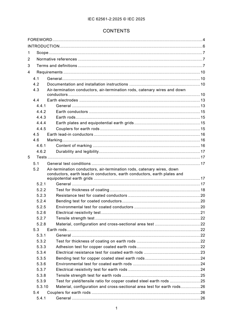
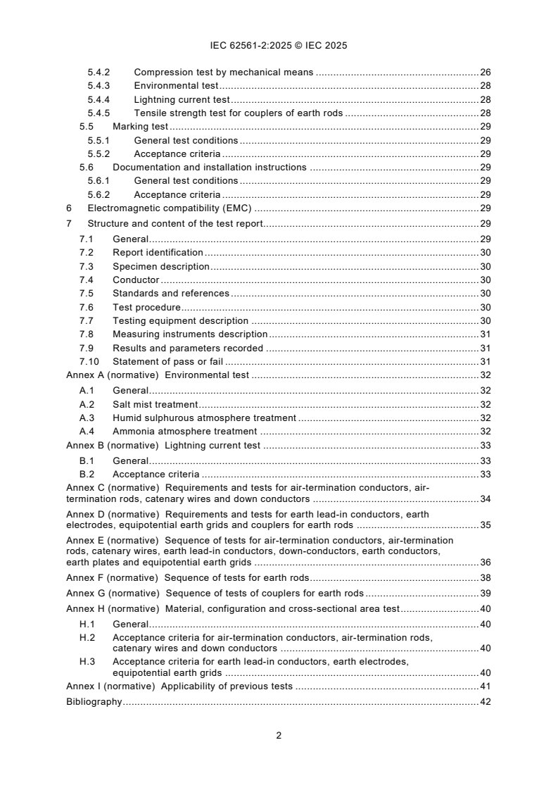
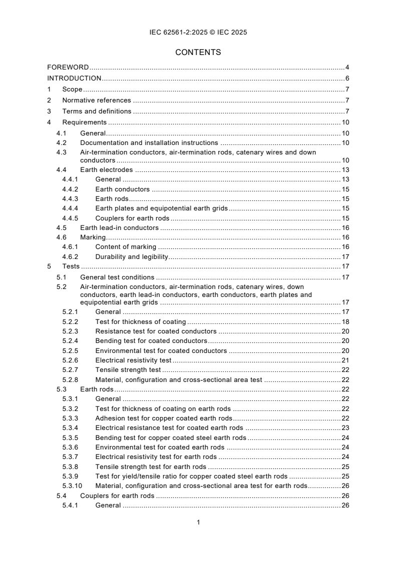
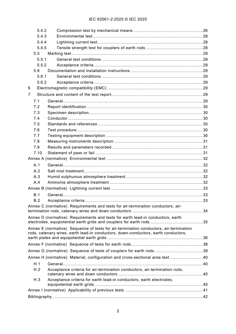
CONTENTS
FOREWORD . 4
INTRODUCTION . 6
1 Scope . 7
2 Normative references . 7
3 Terms and definitions . 7
4 Requirements . 10
4.1 General . 10
4.2 Documentation and installation instructions . 10
4.3 Air-termination conductors, air-termination rods, catenary wires and down
conductors . 10
4.4 Earth electrodes . 13
4.4.1 General . 13
4.4.2 Earth conductors . 15
4.4.3 Earth rods. 15
4.4.4 Earth plates and equipotential earth grids . 15
4.4.5 Couplers for earth rods . 15
4.5 Earth lead-in conductors . 16
4.6 Marking . 16
4.6.1 Content of marking . 16
4.6.2 Durability and legibility. 17
5 Tests . 17
5.1 General test conditions . 17
5.2 Air-termination conductors, air-termination rods, catenary wires, down
conductors, earth lead-in conductors, earth conductors, earth plates and
equipotential earth grids . 17
5.2.1 General . 17
5.2.2 Test for thickness of coating . 18
5.2.3 Resistance test for coated conductors . 20
5.2.4 Bending test for coated conductors . 20
5.2.5 Environmental test for coated conductors . 20
5.2.6 Electrical resistivity test . 21
5.2.7 Tensile strength test . 22
5.2.8 Material, configuration and cross-sectional area test . 22
5.3 Earth rods . 22
5.3.1 General . 22
5.3.2 Test for thickness of coating on earth rods . 22
5.3.3 Adhesion test for copper coated earth rods . 22
5.3.4 Electrical resistance test for coated earth rods . 23
5.3.5 Bending test for copper coated steel earth rods . 24
5.3.6 Environmental test for coated earth rods . 24
5.3.7 Electrical resistivity test for earth rods . 24
5.3.8 Tensile strength test for earth rods . 25
5.3.9 Test for yield/tensile ratio for copper coated steel earth rods . 25
5.3.10 Material, configuration and cross-sectional area test for earth rods . 26
5.4 Couplers for earth rods . 26
5.4.1 General . 26
5.4.2 Compression test by mechanical means . 26
5.4.3 Environmental test . 28
5.4.4 Lightning current test . 28
5.4.5 Tensile strength test for couplers of earth rods . 28
5.5 Marking test . 29
5.5.1 General test conditions . 29
5.5.2 Acceptance criteria . 29
5.6 Documentation and installation instructions . 29
5.6.1 General test conditions . 29
5.6.2 Acceptance criteria . 29
6 Electromagnetic compatibility (EMC) . 29
7 Structure and content of the test report. 29
7.1 General . 29
7.2 Report identification . 30
7.3 Specimen description . 30
7.4 Conductor . 30
7.5 Standards and references . 30
7.6 Test procedure. 30
7.7 Testing equipment description . 30
7.8 Measuring instruments description . 31
7.9 Results and parameters recorded . 31
7.10 Statement of pass or fail . 31
Annex A (normative) Environmental test . 32
A.1 General . 32
A.2 Salt mist treatment . 32
A.3 Humid sulphurous atmosphere treatment . 32
A.4 Ammonia atmosphere treatment . 32
Annex B (normative) Lightning current test . 33
B.1 General . 33
B.2 Acceptance criteria . 33
Annex C (normative) Requirements and tests for air-termination conductors, air-
termination rods, catenary wires and down conductors . 34
Annex D (normative) Requirements and tests for earth lead-in conductors, earth
electrodes, equipotential earth grids and couplers for earth rods . 35
Annex E (normative) Sequence of tests for air-termination conductors, air-termination
rods, catenary wires, earth lead-in conductors, down-conductors, earth conductors,
earth plates and equipotential earth grids . 36
Annex F (normative) Sequence of tests for earth rods . 38
Annex G (normative) Sequence of tests of couplers for earth rods . 39
Annex H (normative) Material, configuration and cross-sectional area test . 40
H.1 General . 40
H.2 Acceptance criteria for air-termination conductors, air-termination rods,
catenary wires and down conductors . 40
H.3 Acceptance criteria for earth lead-in conductors, earth electrodes,
equipotential earth grids . 40
Annex I (normative) Applicability of previous tests . 41
Bibliography . 42
Figure 1 – Coating measurements around the circumference of a round conductor . 18
Figure 2 – Coating measurements of a plate conductor . 18
Figure 3 – Typical test arrangement for adhesion test . 23
Figure 4 – Definitions of upper yield strength R and tensile strength R . 25
eH m
Figure 5 – Typical test arrangement for the compression test by mechanical means . 27
Figure E.1 – Flow chart of tests for air-termination conductors, air-termination rods,
catenary wires, earth lead-in conductors, down-conductors, earth electrodes and
equipotential earth grids . 37
Figure F.1 – Flow chart of tests for earth rods . 38
Figure G.1 – Flow chart of tests of couplers for earth rods . 39
Table 1 – Material, configuration and cross-sectional area of air-termination
conductors, air-termination rods, catenary wires and down-conductors . 11
Table 2 – Material properties . 12
Table 3 – Material, configuration and cross-sectional area of earth lead-in conductors,
earth electrodes and equipotential earth grids . 13
Table B.1 – Lightning impulse current (I ) parameters . 33
imp
Table C.1 – Summary of requirements and tests for various elements tested according
to Table 1 and Table 2 . 34
Table D.1 – Summary of requirements and tests for various elements tested according
to Table 2 and Table 3 . 35
Table I.1 – Differences in the requirements for conductors and earth electrodes
complying with IEC 62561-2:2012 or IEC 62561-2:2018 . 41
INTERNATIONAL ELECTROTECHNICAL COMMISSION
____________
Lightning protection system components (LPSC) -
Part 2: Requirements for conductors and earth electrodes
FOREWORD
1) The International Electrotechnical Commission (IEC) is a worldwide organization for standardization comprising
all national electrotechnical committees (IEC National Committees). The object of IEC is to promote international
co-operation on all questions concerning standardization in the electrical and electronic fields. To this end and
in addition to other activities, IEC publishes International Standards, Technical Specifications, Technical Reports,
Publicly Available Specifications (PAS) and Guides (hereafter referred to as "IEC Publication(s)"). Their
preparation is entrusted to technical committees; any IEC National Committee interested in the subject dealt with
may participate in this preparatory work. International, governmental and non-governmental organizations liaising
with the IEC also participate in this preparation. IEC collaborates closely with the International Organization for
Standardization (ISO) in accordance with conditions determined by agreement between the two organizations.
2) The formal decisions or agreements of IEC on technical matters express, as nearly as possible, an international
consensus of opinion on the relevant subjects since each technical committee has representation from all
interested IEC National Committees.
3) IEC Publications have the form of recommendations for international use and are accepted by IEC National
Committees in that sense. While all reasonable efforts are made to ensure that the technical content of IEC
Publications is accurate, IEC cannot be held responsible for the way in which they are used or for any
misinterpretation by any end user.
4) In order to promote international uniformity, IEC National Committees undertake to apply IEC Publications
transparently to the maximum extent possible in their national and regional publications. Any divergence between
any IEC Publication and the corresponding national or regional publication shall be clearly indicated in the latter.
5) IEC itself does not provide any attestation of conformity. Independent certification bodies provide conformity
assessment services and, in some areas, access to IEC marks of conformity. IEC is not responsible for any
services carried out by independent certification bodies.
6) All users should ensure that they have the latest edition of this publication.
7) No liability shall attach to IEC or its directors, employees, servants or agents including individual experts and
members of its technical committees and IEC National Committees for any personal injury, property damage or
other damage of any nature whatsoever, whether direct or indirect, or for costs (including legal fees) and
expenses arising out of the publication, use of, or reliance upon, this IEC Publication or any other IEC
Publications.
8) Attention is drawn to the Normative references cited in this publication. Use of the referenced publications is
indispensable for the correct application of this publication.
9) IEC draws attention to the possibility that the implementation of this document may involve the use of (a)
patent(s). IEC takes no position concerning the evidence, validity or applicability of any claimed patent rights in
respect thereof. As of the date of publication of this document, IEC had not received notice of (a) patent(s), which
may be required to implement this document. However, implementers are cautioned that this may not represent
the latest information, which may be obtained from the patent database available at https://patents.iec.ch. IEC
shall not be held responsible for identifying any or all such patent rights.
IEC 62561-2 has been prepared by IEC technical committee 81: Lightning protection. It is an
International Standard.
This third edition cancels and replaces the second edition published in 2018. This edition
constitutes a technical revision.
This edition includes the following significant technical changes with respect to the previous
edition:
a) definitions of new conductor types mentioned in this document have been added;
b) the document has been updated in line with IEC 60068-2-52:2017 on salt mist treatment;
c) the document has been updated in line with ISO 22479:2019 on humid sulphurous
atmosphere treatment;
d) a new normative Annex H for material, configuration and cross-sectional area test has been
introduced;
e) a new normative Annex I for applicability of previous tests has been introduced.
f) equipotential earth grid has been introduced.
The text of this International Standard is based on the following documents:
Draft Report on voting
81/794/FDIS 81/800/RVD
Full information on the voting for its approval can be found in the report on voting indicated in
the above table.
The language used for the development of this International Standard is English.
This document was drafted in accordance with ISO/IEC Directives, Part 2, and developed in
accordance with ISO/IEC Directives, Part 1 and ISO/IEC Directives, IEC Supplement, available
at www.iec.ch/members_experts/refdocs. The main document types developed by IEC are
described in greater detail at www.iec.ch/publications.
A list of all parts in the IEC 62561 series, published under the general title Lightning protection
system components (LPSC), can be found on the IEC website.
The committee has decided that the contents of this document will remain unchanged until the
stability date indicated on the IEC website under webstore.iec.ch in the data related to the
specific document. At this date, the document will be
– reconfirmed,
– withdrawn, or
– revised.
INTRODUCTION
This part of IEC 62561 deals with the requirements and tests for lightning protection system
components (LPSC), specifically conductors and earth electrodes, used for the installation of a
lightning protection system (LPS) designed and implemented according to the IEC 62305
series.
1 Scope
This part of IEC 62561 specifies the requirements and tests for
– metallic conductors (other than "natural" conductors) that form part of the air-termination
and down-conductor systems, and
– metallic earth electrodes that form part of the earth-termination system.
NOTE 1 Additional requirements can be necessary for conductors and earth electrodes intended for use in
hazardous environments.
NOTE 2 In CENELEC member countries, testing requirements of components for explosive atmospheres are
specified in CLC/TS 50703-2.
2 Normative references
The following documents are referred to in the text in such a way that some or all of their content
constitutes requirements of this document. For dated references, only the edition cited applies.
For undated references, the latest edition of the referenced document (including any
amendments) applies.
IEC 60068-2-52:2017, Environmental testing – Part 2-52: Tests – Test Kb: Salt mist, cyclic
(sodium, chloride solution)
IEC 60228, Conductors of insulated cables
ISO 2178, Non-magnetic coatings on magnetic substrates – Measurement of coating thickness
– Magnetic method
ISO 1460, Metallic coatings – Hot dip galvanized coatings on ferrous materials – Gravimetric
determination of the mass per unit area
ISO 1461:2022, Hot dip galvanized coatings on fabricated iron and steel articles –
Specifications and test methods
ISO 6892-1, Metallic materials – Tensile testing – Part 1: Method of test at room temperature
ISO 6957:1988, Copper alloys – Ammonia test for stress corrosion resistance
ISO 22479:2019, Corrosion of metals and alloys – Sulphur dioxide test in a humid atmosphere
(fixed gas method)
3 Terms and definitions
For the purposes of this document, the following terms and definitions apply.
ISO and IEC maintain terminology databases for use in standardization at the following
addresses:
– IEC Electropedia: available at https://www.electropedia.org/
– ISO Online browsing platform: available at https://www.iso.org/obp
3.1
air-termination system
part of an external lightning protection system (LPS) intended to intercept lightning flashes
EXAMPLE Air-termination rods, air-termination conductors and catenary wires.
3.2
air-termination rod
part of the air-termination system consisting of a metal rod for intercepting and conducting
flashes to the down-conductor and earthing system of the lightning protection system (LPS)
3.3
air-termination conductor
part of the air-termination system consisting of a conductor for intercepting and conducting
flashes to the down-conductor and earthing system of the lightning protection system (LPS)
3.4
catenary wire
part of the air-termination system consisting of an overhead wire for intercepting and conducting
flashes to the down-conductor and earthing system of the lightning protection system (LPS)
3.5
copper coated steel
steel that is manufactured through a continuous electro-plating process of copper over steel
core, resulting in a permanent molecular bond between the two materials
3.6
down-conductor system
part of an external LPS intended to conduct lightning current between the air-termination system
and the earth-termination system
3.7
down-conductor
part of the down-conductor system intended to conduct lightning current from the air-termination
system to the earth-termination system of the LPS
3.8
earth lead-in conductor
conductor installed between the down-conductor or test joint and the earth electrode intended
to provide connection of the earth electrode with the test joint and can be partially buried in
soil or partially embedded in concrete and partially placed in air
Note 1 to entry: An earth lead-in conductor can also provide mechanical protection against accidental stresses to
the down conductor system.
3.9
earth-termination system
part of an external lightning protection system, which is intended to conduct and disperse
lightning current to the earth
3.10
earth electrode
ground electrode, USA
part or group of parts of the earth-termination system which provides direct electrical contact
with the earth and disperses lightning current into the earth
EXAMPLE Tape, wire, earth plate, lattice earth plate, meshed earth plate, solid earth rod, tubular earth rod.
3.11
earth conductor
ground conductor, USA
earth electrode consisting of a conductor buried in the ground
3.12
earth plate
metallic earth electrode consisting of a solid plate buried in the ground or a lattice plate buried
in the ground
3.13
earth rod
earth electrode consisting of a solid or tubular metal rod driven into the ground
3.14
earth-rod-driving-head
tool used in those applications where it is necessary to drive the earth rod
3.15
couplers for earth rods
part of the earth-termination system that facilitates the coupling of one section of an earth rod
to another for the purpose of deep driving
Note 1 to entry: Male and female or plug and socket connections of earth rods are also defined as couplers.
3.16
hot dipped galvanized steel
steel coated by a process which alloys with the surface of the base metal when immersing the
metal in a bath of molten zinc at a temperature of around 450 °C (842 °F)
3.17
type test
test required to be made before supplying a type of material covered by IEC 62561-2 on a
general commercial basis, in order to demonstrate satisfactory performance characteristics to
meet the intended application
3.18
stranded conductor
conductor consisting of a number of individual wires or strands all or some of which generally
have a helical form
Note 1 to entry: The cross-section of a stranded conductor can be circular or otherwise shaped.
Note 2 to entry: The term "strand" is also used to designate a single wire.
[SOURCE: IEC 60050-461:2008, 461-01-07]
3.19
rope lay conductor
conductor composed of a central core surrounded by one or more layers of helically laid groups
of wires
3.20
smooth weave stranded conductor
conductor constructed of multi-strand soft drawn wire, interwoven in a basket weave
configuration so as to avoid fraying in application
3.21
equipotential earth grid
mat consisting of an array of conductor intended for potential equalization
4 Requirements
4.1 General
Conductors and earth electrodes shall be designed in such a manner that, when they are
installed in accordance with the manufacturer's instructions, their performance shall be reliable,
stable and safe to persons and surrounding equipment.
The choice of a material depends on its ability to match the particular application requirements
such as life cycle of the material, effects from galvanic corrosion and compatibility with other
interconnected materials or services.
Summaries of the requirements for tests are given in Annex C and Annex D and the sequence
of tests in Annex E, Annex F and Annex G.
4.2 Documentation and installation instructions
The manufacturer or supplier of the conductors and rods shall provide adequate information in
their documentation or installation instructions, for example by drawings or photographs, to
ensure that the installer of the conductors and rods can select and install the materials in
accordance with IEC 62305-3 and IEC 62305-4.
To facilitate the installer, where it is necessary, the manufacturer or supplier may recommend
the proper tools for their installation and instruments in order to perform specified
measurements by IEC 62305 (all parts). In addition, where it is necessary to recommend a
training for the safe selection and use of LPS components.
Documentation and installation instructions content shall not be in contradiction with the content
of the relative testing report of each component.
Instructions are checked as per their completeness in accordance with 5.6.
4.3 Air-termination conductors, air-termination rods, catenary wires and down
conductors
The material, configuration and cross-sectional area of the conductors and rods shall be in
accordance with Table 1. Their mechanical and electrical characteristics shall be in accordance
with Table 2.
Other materials may be used if they possess equivalent mechanical and electrical
characteristics and corrosion resistance properties for the intended application.
Other configurations may be used if the relevant cross-sections are met.
If dimensions, materials or configurations other than those shown in Table 1 and Table 2 are
applied, it is possible to use such after a successful electrical test with lightning current as per
Table B.1, class H, as well as all the tests required by Clause 5.
Coated conductors and air-termination rods shall be corrosion-resistant and the coating shall
exhibit good adherence to the base material.
Compliance is checked by inspection and by the tests as follows:
a) for coated specimens, according to 5.2.2, 5.2.3, 5.2.4, 5.2.5, 5.2.6, 5.2.7, 5.2.8 and 5.5;
5.5.
b) for uncoated specimens, according to 5.2.6, 5.2.7, 5.2.8 and
A summary of requirements for the cross-sectional area, mechanical and electrical
characteristics as well as tests is given in Annex C. The corresponding flow chart is shown in
Annex E.
Table 1 – Material, configuration and cross-sectional area of air-termination conductors,
air-termination rods, catenary wires and down-conductors
a
Material Configuration Recommended dimensions
Cross-sectional area
mm
Copper, Solid tape ≥ 50 2 mm thickness
b
d
Tin plated copper ≥ 50 8 mm diameter
Solid round
f k
≥ 50 1,14 mm up to 1,7 mm strand diameter
Stranded
g
≥ 176 15 mm diameter
Rod solid round
Tubular rod ≥ 100 2 mm wall thickness
i
Rope lay conductor 1,04 mm strand diameter
≥ 50
and smooth weave
stranded conductor
Aluminium Solid tape ≥ 70 3 mm thickness
Solid round ≥ 50 8 mm diameter
f k
≥ 50 1,63 mm strand diameter
Stranded
j
Rope lay conductor 2,08 mm strand diameter
≥ 50
and smooth weave
stranded conductor
Copper coated
Solid round ≥ 50 8 mm diameter
e
aluminium alloy
Aluminium alloy Solid tape ≥ 50 2,5 mm thickness
Solid round ≥ 50 8 mm diameter
f k
≥ 50 1,7 mm strand diameter
Stranded
g
≥ 176 15 mm diameter
Rod solid round
Tubular rod ≥ 100 2 mm wall thickness
Hot dipped galvanized Solid tape ≥ 50 2,5 mm thickness
steel
Solid round ≥ 50 8 mm diameter
Stranded ≥ 50 1,7 mm strand diameter
g
≥ 176 15 mm diameter
Rod solid round
Tubular rod ≥ 100 2 mm wall thickness
Solid round ≥ 50 8 mm diameter
a
Material Configuration Recommended dimensions
Cross-sectional area
mm
e
Solid tape ≥ 50 2,5 mm thickness
Copper coated steel
c h
≥ 50 2 mm thickness
Stainless steel Solid tape
h
≥ 50 8 mm diameter
Solid round
Stranded ≥ 70 1,7 mm strand diameter
g
≥ 176 15 mm diameter
Rod Solid round
Tubular rod ≥ 100 2 mm wall thickness
NOTE For the application of the conductors, see IEC 62305-3.
a
Manufacturing tolerance: −3 %.
b
Hot dipped or electroplated; minimum thickness coating of 1 μm. There is no requirement to measure the tin
plating on copper.
c
Chromium ≥ 16 %; nickel ≥ 8 %; carbon ≤ 0,08 %.
d 2 2
50 mm (8 mm in diameter) may be reduced to 28 mm (6 mm in diameter) in certain applications where
mechanical strength is not an essential requirement. Consideration should, in this case, be given to reducing
the spacing between the fasteners.
e
Minimum 70 μm radial copper coating.
f
The cross-sectional area of stranded conductors is determined by the resistance of the conductor according to
IEC 60228 (bare stranded wire should be calculated based upon its diameter by measurements taken with
calipers or a micrometer).
g
Applicable for air-termination rods. For air-termination rods where mechanical stress such as wind loading is
not critical, a 9,5 mm diameter, 1 m long rod may be used.
h 2
If thermal and mechanical considerations are important, then these values should be increased to 75 mm .
i 2
In some countries (e.g. United States), the minimum cross area is increased to not less than 58 mm for
structures over 23 m in height, with a minimum strand diameter 1,04 mm.
j 2
In some countries (e.g. Unites States), the minimum cross area is increased to not less than 97 mm for
structures over 23 m in height, with a minimum strand diameter 2,08 mm.
k
In Japan, a strand diameter of 2 mm is used.
Table 2 – Material properties
Maximum electrical resistivity Tensile strength
Material
2 b
μΩm
N/mm
Copper
0,019
Aluminium
0,031
Copper coated aluminium alloy
0,031
Copper coated steel
0,258
60 to 510
Aluminium alloy
0,041
Hot dipped galvanized steel
0,258
Aluminium coated steel stranded wire
0,075
Copper coated steel stranded wire
0,064
Hot dipped galvanized steel (earth rods)
0,258
a
350 to 770
Copper coated steel (earth rods)
0,258
Stainless steel
0,824
a
Yield/tensile ratio 0,80 to 0,95.
b
Based on dimensions/tests of only core material of coated conductors.
4.4 Earth electrodes
4.4.1 General
The cross-sectional area of earth electrodes (earth conductors, earth plates, earth rods) and
earth lead-in conductors partially in soil, their material and their configuration shall be in
accordance with Table 3. Moreover, their mechanical and electrical characteristics shall be in
accordance with Table 2.
Other configurations may be used if the relevant cross-sectional area is met.
If materials or configurations other than those shown in Table 2 and Table 3 are applied, it is
possible to use such after a successful electrical test with lightning current as per Table B.1,
class H, as well as all the tests required by Clause 5.
Coated earth electrodes shall be corrosion-resistant and the coating shall exhibit good
adherence to the base material.
Table 3 – Material, configuration and cross-sectional area of earth lead-in conductors,
earth electrodes and equipotential earth grids
Surface
a
Cross-sectional area
area
Earth
l
Material Recommended dimensions
Configuration
electrode/
Earth Earth
earth lead
p
rod
plate
in
conductor
2 2 2
mm mm cm
i q
Stranded ≥ 50 1,7 mm strand diameter
Solid round ≥ 50 8 mm diameter
Solid tape ≥ 50 2 mm thick
Solid round ≥ 176 15 mm diameter
Copper,
20 mm diameter with 2 mm wall
Tubular rod ≥ 110
thickness
Tin plated
f
g
copper
Solid plate ≥ 2 500 500 mm × 500 mm and 1,5 mm thick
600 mm × 600 mm consisted of
g
≥ 3 600 25 mm × 2 mm section for tape or
Lattice plate
8 mm diameter for round conductor
Equipotential Mesh size 250 mm to 500 mm,
o
earth grid conductor 4 mm diameter
Solid round ≥ 78 10 mm diameter
b
Solid round 14 mm diameter
≥ 150
25 mm diameter with 2 mm wall
b
Tubular rod
≥ 140
thickness
Solid tape ≥ 90 3 mm thick
Hot dipped
Solid plate ≥ 2 500 500 mm × 500 mm and 3 mm thick
galvanized
steel
600 mm × 600 mm consisted of
d
≥ 3 600 30 mm × 3 mm section for tape or
Lattice plate
10 mm diameter for round conductor
Equipotential Mesh size 250-500 mm, conductor
o
earth grid 4 mm diameter
e
Profile 3 mm thick
q
Stranded ≥ 70
1,7 mm strand diameter
Surface
a
Cross-sectional area
area
Earth
l
Material Recommended dimensions
Configuration
electrode/
Earth Earth
earth lead
p
rod
plate
in
conductor
2 2 2
mm mm cm
Solid round ≥ 78 10 mm diameter
Bare steel
k,p
Solid tape ≥ 75 3 mm thick
m h
14 mm diameter
Solid round ≥ 150
Copper
m
≥ 50 8 mm diameter
coated Solid round
c
steel
n
Solid tape ≥ 90 3 mm thick
Solid round ≥ 78 10 mm diameter
h
Solid round 15 mm diameter
≥ 176
Solid tape ≥ 100 2 mm thick
Stainless
25 mm diameter with 2 mm wall
j
Tubular rod ≥ 140
steel
thickness
Equipotential
Mesh size 250 mm to 500 mm,
o
conductor 4 mm diameter
earth grid
Solid plate ≥ 2 500 500 mm × 500 mm and 2 mm thick
NOTE For the application of the earth electrodes, see IEC 62305-3.
a
Manufacturing tolerance: −3 %.
b
Threads, where utilized, shall be machined prior to hot dipped galvanizing.
c
The copper shall be intrinsically bonded to the steel. The coating can be measured using an electronic coating
measuring thickness instrument.
d
Lattice plate constructed with a minimum total conductor length of 4,8 m.
e 2
Different profiles are permitted with a cross section of 290 mm and a minimum thickness of 3 mm, for example
cross profile.
f
Hot dipped or electroplated; minimum thickness coating of 1 μm. There is no need to measure the tin-plated
copper if it is stated that it is present for aesthetic reasons only.
g 2
In some countries (e.g. Unites States), the cross-sectional area may be reduced to ≥ 1 800 cm and the
thickness to ≥ 0,8 mm.
h 2
In some countries (e.g. Unites States), the cross-sectional area may be reduced to 125 mm .
i
The cross-sectional area of insulated stranded conductors is determined by the resistance of the conductor
according to IEC 60228 (bare stranded wire should be calculated based upon its diameter by measurements
taken with calipers or a micrometer).
j
Chromium ≥ 16 %, nickel ≥ 5 %, molybdenum ≥ 2 %, carbon ≤ 0,08 %.
k
Shall be embedded in concrete for a minimum depth of 50 mm.
l
Other configurations may be used if the relevant cross-sectional area are met.
m
250 μm minimum radial coating which may be reduced to not less than 100 μm where special precautions to
avoid mechanical damage of copper during the installation process (e.g. trenches, drilled holes or special
protective tips) are taken according to the manufacturer's instructions.
n
70 μm minimum radial coating; in corrosive environment for solid tape earth conductors, it is recommended to
use copper-coated steel with a coating of 250 μm – for corrosive environment, refer to IEC 62561-7.
o
For equipotential earth grid, the dimensions vary depending on the intended area of equipotential bonding.
p
Not to be used as earth lead-in conductor unless fully embedded in concrete.
q
In Japan the smallest strand diameter of stranded wire used is 2 mm.
4.4.2 Earth conductors
Earth conductors shall be corrosion-resistant and any coating shall exhibit good adherence to
the base material. Compliance is checked by inspection and by the tests as follows:
a) for coated specimens, according to 5.2.2, 5.2.3, 5.2.4, 5.2.5, 5.2.6, 5.2.7, 5.2.8 and 5.5;
b) for uncoated specimens, according to 5.2.6, 5.2.7, 5.2.8 and 5.5.
A summary of requirements for the cross-sectional area, mechanical and electrical
characteristics as well as tests is given in Annex D. The corresponding flow chart is shown in
Annex E.
4.4.3 Earth rods
Earth rods shall be mechanically robust to ensure correct installation. The material of choice
shall be sufficiently malleable to ensure that no cracking of the rod takes place during
installation or after their covering in the ground.
The threads on the rods, if any, shall be smooth and fully formed. For coated rods, the coating
shall extend over the threads. A lead-in chamfer or point is recommended to facilitate driving.
If the threads are completely sealed, there is no need to apply a coating. This shall be verified
by test according 5.3.6.
For electroplated rods, such as copper-coated steel rods, it is desirable to roll the thread profile
to ensure that no copper is detached from the steel.
Compliance is checked by inspection and by the tests as follows:
a) for copper coated steel earth rod specimens, according to 5.3.2, 5.3.3, 5.3.4 5.3.5, 5.3.6,
5.3.7, 5.3.8, 5.3.9, 5.3.10 and 5.5;
b) for hot dipped galvanized steel earth rod specimens, according to 5.3.2, 5.3.4, 5.3.6, 5.3.7,
5.3.8, 5.3.10 and 5.5;
c) for uncoated earth rod specimens, according to 5.3.7, 5.3.8, 5.3.10 and 5.5.
A summary of requirements for the cross-sectional area, mechanical and electrical
characteristics as well as tests is given in Annex D. The corresponding flow chart is shown in
Annex F.
4.4.4 Earth plates and equipotential earth grids
Conductors of earth plates and equipotential earth grids shall be corrosion-resistant and any
coating shall exhibit adherence to the base material.
Compliance is checked by inspection and by the tests as follows:
a) for coated steel specimens, according to 5.2.2, 5.2.3, 5.2.4, 5.2.5, 5.2.6, 5.2.8 and 5.5;
b) for uncoated specimens, according to 5.2.6, 5.2.8 and 5.5.
A summary of the requirements for dimensions, mechanical and electrical characteristics as
well as tests is given in Annex D. The corresponding flow chart is shown in Annex E.
4.4.5 Couplers for earth rods
Earth rods can be extended allowing them to be driven deeper into the ground. This can be
achieved by means of a joint or a coupling device.
The choice of material shall be compatible with that of the earth rod being joined.
It shall be sufficiently mechanically robust to withstand the driving forces generated during
installation.
It shall also exhibit good corrosion resistance.
Threaded externally couplers shall be of a sufficient length to ensure no threads on the earth
rod are exposed when installed.
Threaded internally couplers shall ensure that the mating faces of the earth rods come in
contact after assembly.
Threaded-internally couplers and threaded-externally couplers shall have sufficient lightning
current carrying capability. According to the ability to withstand lightning current, couplers for
earth rods are classified as follows:
a) class H for heavy duty;
b) class N for normal duty.
The selection of class H and N should be perfor
...
IEC 62561-2 ®
Edition 3.0 2025-09
INTERNATIONAL
STANDARD
REDLINE VERSION
Lightning protection system components (LPSC) -
Part 2: Requirements for conductors and earth electrodes
ICS 29.020; 91.120.40 ISBN 978-2-8327-0758-6
All rights reserved. Unless otherwise specified, no part of this publication may be reproduced or utilized in any form or
by any means, electronic or mechanical, including photocopying and microfilm, without permission in writing from either
IEC or IEC's member National Committee in the country of the requester. If you have any questions about IEC copyright
or have an enquiry about obtaining additional rights to this publication, please contact the address below or your local
IEC member National Committee for further information.
IEC Secretariat Tel.: +41 22 919 02 11
3, rue de Varembé info@iec.ch
CH-1211 Geneva 20 www.iec.ch
Switzerland
About the IEC
The International Electrotechnical Commission (IEC) is the leading global organization that prepares and publishes
International Standards for all electrical, electronic and related technologies.
About IEC publications
The technical content of IEC publications is kept under constant review by the IEC. Please make sure that you have the
latest edition, a corrigendum or an amendment might have been published.
IEC publications search - IEC Products & Services Portal - products.iec.ch
webstore.iec.ch/advsearchform Discover our powerful search engine and read freely all the
The advanced search enables to find IEC publications by a publications previews, graphical symbols and the glossary.
variety of criteria (reference number, text, technical With a subscription you will always have access to up to date
committee, …). It also gives information on projects, content tailored to your needs.
replaced and withdrawn publications.
Electropedia - www.electropedia.org
The world's leading online dictionary on electrotechnology,
IEC Just Published - webstore.iec.ch/justpublished
Stay up to date on all new IEC publications. Just Published containing more than 22 500 terminological entries in English
details all new publications released. Available online and and French, with equivalent terms in 25 additional languages.
once a month by email. Also known as the International Electrotechnical Vocabulary
(IEV) online.
IEC Customer Service Centre - webstore.iec.ch/csc
If you wish to give us your feedback on this publication or
need further assistance, please contact the Customer
Service Centre: sales@iec.ch.
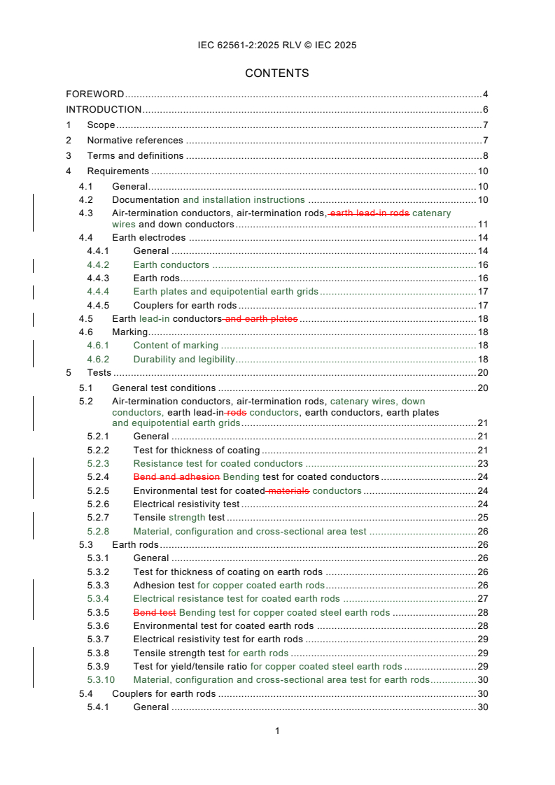
CONTENTS
FOREWORD . 4
INTRODUCTION . 6
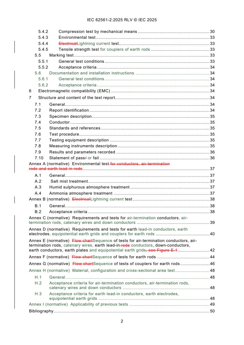
1 Scope . 7
2 Normative references . 7
3 Terms and definitions . 8
4 Requirements . 10
4.1 General . 10
4.2 Documentation and installation instructions . 10
4.3 Air-termination conductors, air-termination rods, earth lead-in rods catenary
wires and down conductors . 11
4.4 Earth electrodes . 14
4.4.1 General . 14
4.4.2 Earth conductors . 16
4.4.3 Earth rods. 16
4.4.4 Earth plates and equipotential earth grids . 17
4.4.5 Couplers for earth rods . 17
4.5 Earth lead-in conductors and earth plates . 18
4.6 Marking . 18
4.6.1 Content of marking . 18
4.6.2 Durability and legibility. 18
5 Tests . 20
5.1 General test conditions . 20
5.2 Air-termination conductors, air-termination rods, catenary wires, down
conductors, earth lead-in rods conductors, earth conductors, earth plates
and equipotential earth grids . 21
5.2.1 General . 21
5.2.2 Test for thickness of coating . 21
5.2.3 Resistance test for coated conductors . 23
5.2.4 Bend and adhesion Bending test for coated conductors . 24
5.2.5 Environmental test for coated materials conductors . 24
5.2.6 Electrical resistivity test . 24
5.2.7 Tensile strength test . 25
5.2.8 Material, configuration and cross-sectional area test . 26
5.3 Earth rods . 26
5.3.1 General . 26
5.3.2 Test for thickness of coating on earth rods . 26
5.3.3 Adhesion test for copper coated earth rods . 26
5.3.4 Electrical resistance test for coated earth rods . 27
5.3.5 Bend test Bending test for copper coated steel earth rods . 28
5.3.6 Environmental test for coated earth rods . 28
5.3.7 Electrical resistivity test for earth rods . 29
5.3.8 Tensile strength test for earth rods . 29
5.3.9 Test for yield/tensile ratio for copper coated steel earth rods . 29
5.3.10 Material, configuration and cross-sectional area test for earth rods . 30
5.4 Couplers for earth rods . 30
5.4.1 General . 30
5.4.2 Compression test by mechanical means . 30
5.4.3 Environmental test . 33
5.4.4 ElectricalLightning current test . 33
5.4.5 Tensile strength test for couplers of earth rods . 33
5.5 Marking test . 33
5.5.1 General test conditions . 33
5.5.2 Acceptance criteria . 34
5.6 Documentation and installation instructions . 34
5.6.1 General test conditions . 34
5.6.2 Acceptance criteria . 34
6 Electromagnetic compatibility (EMC) . 34
7 Structure and content of the test report. 34
7.1 General . 34
7.2 Report identification . 34
7.3 Specimen description . 35
7.4 Conductor . 35
7.5 Standards and references . 35
7.6 Test procedure. 35
7.7 Testing equipment description . 35
7.8 Measuring instruments description . 35
7.9 Results and parameters recorded . 36
7.10 Statement of pass/ or fail . 36
Annex A (normative) Environmental test for conductors, air-termination
rods and earth lead-in rods . 37
A.1 General . 37
A.2 Salt mist treatment . 37
A.3 Humid sulphurous atmosphere treatment . 37
A.4 Ammonia atmosphere treatment . 37
Annex B (normative) ElectricalLightning current test . 38
B.1 General . 38
B.2 Acceptance criteria . 38
Annex C (normative) Requirements and tests for air-termination conductors, air-
termination rods, catenary wires and down conductors . 39
Annex D (normative) Requirements and tests for earth lead-in conductors, earth
electrodes, equipotential earth grids and couplers for earth rods . 40
Annex E (normative) Flow chartSequence of tests for air-termination conductors, air-
termination rods, catenary wires, earth lead-in rods conductors, down-conductors,
earth conductors, earth plates and equipotential earth grids, see Figure E.1 . 42
Annex F (normative) Flow chartSequence of tests for earth rods . 44
Annex G (normative) Flow chartSequence of tests of couplers for earth rods . 46
Annex H (normative) Material, configuration and cross-sectional area test . 48
H.1 General . 48
H.2 Acceptance criteria for air-termination conductors, air-termination rods,
catenary wires and down conductors . 48
H.3 Acceptance criteria for earth lead-in conductors, earth electrodes,
equipotential earth grids . 48
Annex I (normative) Applicability of previous tests . 49
Bibliography . 50
Figure 1 – Coating measurements around the circumference of a round conductor . 22
Figure 2 – Coating measurements of a plate conductor . 22
Figure 3 – Typical test arrangement for adhesion test . 27
Figure 4 – Definitions of upper yield strength R and tensile strength R . 30
eH m
Figure 5 – Typical test arrangement for the compression test by mechanical means . 32
Figure E.1 – Flow chart of tests for air-termination conductors, air-termination rods,
catenary wires, earth lead-in rods conductors, down-conductors, earth conductors
electrodes and equipotential earth plates grids . 43
Figure F.1 – Flow chart of tests for earth rods . 45
Figure G.1 – Flow chart of tests of couplers for earth rods . 47
Table 1 – Material, configuration and cross-sectional area of air-termination
g
conductors, air-termination rods, earth lead-in rods catenary wires and down-
conductors . 12
Table 2 – Mechanical and electrical characteristics of air-termination
conductors, air-termination rods, earth lead-in rods, down-conductors and earth
electrodes .
Table 2 – Material properties . 13
Table 3 – Material, configuration and cross-sectional area of earth electrodes .
Table 3 – Material, configuration and cross-sectional area of earth lead-in conductors,
earth electrodes and equipotential earth grids . 14
Table B.1 – Lightning impulse current (I ) parameters . 38
imp
Table C.1 – Summary of requirements and tests for various elements tested according
to Table 1 and Table 2 . 39
Table D.1 – Summary of requirements and tests for various elements tested according
to Table 2 and Table 3 . 40
Table I.1 – Differences in the requirements for conductors and earth electrodes
complying with IEC 62561-2:2012 or IEC 62561-2:2018 . 49
INTERNATIONAL ELECTROTECHNICAL COMMISSION
____________
Lightning protection system components (LPSC) -
Part 2: Requirements for conductors and earth electrodes
FOREWORD
1) The International Electrotechnical Commission (IEC) is a worldwide organization for standardization comprising
all national electrotechnical committees (IEC National Committees). The object of IEC is to promote international
co-operation on all questions concerning standardization in the electrical and electronic fields. To this end and
in addition to other activities, IEC publishes International Standards, Technical Specifications, Technical Reports,
Publicly Available Specifications (PAS) and Guides (hereafter referred to as "IEC Publication(s)"). Their
preparation is entrusted to technical committees; any IEC National Committee interested in the subject dealt with
may participate in this preparatory work. International, governmental and non-governmental organizations liaising
with the IEC also participate in this preparation. IEC collaborates closely with the International Organization for
Standardization (ISO) in accordance with conditions determined by agreement between the two organizations.
2) The formal decisions or agreements of IEC on technical matters express, as nearly as possible, an international
consensus of opinion on the relevant subjects since each technical committee has representation from all
interested IEC National Committees.
3) IEC Publications have the form of recommendations for international use and are accepted by IEC National
Committees in that sense. While all reasonable efforts are made to ensure that the technical content of IEC
Publications is accurate, IEC cannot be held responsible for the way in which they are used or for any
misinterpretation by any end user.
4) In order to promote international uniformity, IEC National Committees undertake to apply IEC Publications
transparently to the maximum extent possible in their national and regional publications. Any divergence between
any IEC Publication and the corresponding national or regional publication shall be clearly indicated in the latter.
5) IEC itself does not provide any attestation of conformity. Independent certification bodies provide conformity
assessment services and, in some areas, access to IEC marks of conformity. IEC is not responsible for any
services carried out by independent certification bodies.
6) All users should ensure that they have the latest edition of this publication.
7) No liability shall attach to IEC or its directors, employees, servants or agents including individual experts and
members of its technical committees and IEC National Committees for any personal injury, property damage or
other damage of any nature whatsoever, whether direct or indirect, or for costs (including legal fees) and
expenses arising out of the publication, use of, or reliance upon, this IEC Publication or any other IEC
Publications.
8) Attention is drawn to the Normative references cited in this publication. Use of the referenced publications is
indispensable for the correct application of this publication.
9) IEC draws attention to the possibility that the implementation of this document may involve the use of (a)
patent(s). IEC takes no position concerning the evidence, validity or applicability of any claimed patent rights in
respect thereof. As of the date of publication of this document, IEC had not received notice of (a) patent(s), which
may be required to implement this document. However, implementers are cautioned that this may not represent
the latest information, which may be obtained from the patent database available at https://patents.iec.ch. IEC
shall not be held responsible for identifying any or all such patent rights.
This redline version of the official IEC Standard allows the user to identify the changes made
to the previous edition IEC 62561-2:2018. A vertical bar appears in the margin wherever a
change has been made. Additions are in green text, deletions are in strikethrough red text.
IEC 62561-2 has been prepared by IEC technical committee 81: Lightning protection. It is an
International Standard.
This third edition cancels and replaces the second edition published in 2018. This edition
constitutes a technical revision.
This edition includes the following significant technical changes with respect to the previous
edition:
a) definitions of new conductor types mentioned in this document have been added;
b) the document has been updated in line with IEC 60068-2-52:2017 on salt mist treatment;
c) the document has been updated in line with ISO 22479:2019 on humid sulphurous
atmosphere treatment;
d) a new normative Annex H for material, configuration and cross-sectional area test has been
introduced;
e) a new normative Annex I for applicability of previous tests has been introduced.
f) equipotential earth grid has been introduced.
The text of this International Standard is based on the following documents:
Draft Report on voting
81/794/FDIS 81/800/RVD
Full information on the voting for its approval can be found in the report on voting indicated in
the above table.
The language used for the development of this International Standard is English.
This document was drafted in accordance with ISO/IEC Directives, Part 2, and developed in
accordance with ISO/IEC Directives, Part 1 and ISO/IEC Directives, IEC Supplement, available
at www.iec.ch/members_experts/refdocs. The main document types developed by IEC are
described in greater detail at www.iec.ch/publications.
A list of all parts in the IEC 62561 series, published under the general title Lightning protection
system components (LPSC), can be found on the IEC website.
The committee has decided that the contents of this document will remain unchanged until the
stability date indicated on the IEC website under webstore.iec.ch in the data related to the
specific document. At this date, the document will be
– reconfirmed,
– withdrawn, or
– revised.
INTRODUCTION
This part of IEC 62561 deals with the requirements and tests for lightning protection system
components (LPSC), specifically conductors and earth electrodes, used for the installation of a
lightning protection system (LPS) designed and implemented according to the IEC 62305
series.
1 Scope
This part of IEC 62561 specifies the requirements and tests for
– metallic conductors (other than "natural" conductors) that form part of the air-termination
and down-conductor systems, and
– metallic earth electrodes that form part of the earth-termination system.
NOTE 1 Additional requirements can be necessary for conductors and earth electrodes intended for use in
hazardous environments.
NOTE 2 In CENELEC member countries, testing requirements of components for explosive atmospheres are
specified in CLC/TS 50703-2.
2 Normative references
The following documents are referred to in the text in such a way that some or all of their content
constitutes requirements of this document. For dated references, only the edition cited applies.
For undated references, the latest edition of the referenced document (including any
amendments) applies.
IEC 60068-2-52:19962017, Environmental testing – Part 2-52: Tests – Test Kb: Salt mist, cyclic
(sodium, chloride solution)
IEC 60228, Conductors of insulated cables
IEC 62305-3, Protection against lightning – Part 3: Physical damage to structures and life
hazard
IEC 62305-4, Protection against lightning – Part 4: Electrical and electronic systems within
structures
IEC 62561-1:2012, Lightning protection system components (LPSC) – Part 1, Requirements for
connection components
ISO 2178, Non-magnetic coatings on magnetic substrates – Measurement of coating thickness
– Magnetic method
ISO 1460, Metallic coatings – Hot dip galvanized coatings on ferrous materials – Gravimetric
determination of the mass per unit area
ISO 1461:2022, Hot dip galvanized coatings on fabricated iron and steel articles –
Specifications and test methods
ISO 6892-1, Metallic materials – Tensile testing – Part 1: Method of test at room temperature
ISO 6957:1988, Copper alloys – Ammonia test for stress corrosion resistance
ISO 6988:1985, Metallic and other non-organic coatings – Sulphur dioxide test with general
condensation of moisture
ISO 22479:2019, Corrosion of metals and alloys – Sulphur dioxide test in a humid atmosphere
(fixed gas method)
3 Terms and definitions
For the purposes of this document, the following terms and definitions apply.
ISO and IEC maintain terminology databases for use in standardization at the following
addresses:
– IEC Electropedia: available at https://www.electropedia.org/
– ISO Online browsing platform: available at https://www.iso.org/obp
3.1
air-termination system
part of an external lightning protection system (LPS using metallic elements such as rods, mesh
conductors or catenary wires) intended to intercept lightning flashes
EXAMPLE Air-termination rods, air-termination conductors and catenary wires.
3.2
air-termination rod
part of the air-termination system consisting of a metal rod for intercepting and conducting
flashes to the down-conductor and earthing system components of the lightning protection
system (LPS)
3.3
air-termination conductor
part of the air-termination system consisting of a conductor for intercepting and conducting
flashes to the down-conductor and earthing system components of the lightning protection
system (LPS)
3.4
catenary wire
part of the air-termination system consisting of an overhead wire for intercepting and conducting
flashes to the down-conductor and earthing system of the lightning protection system (LPS)
3.5
copper coated steel
steel that is manufactured through a continuous electro-plating process of copper over steel
core, resulting in a permanent molecular bond between the two materials
3.6
down-conductor system
part of an external LPS intended to conduct lightning current between the air-termination system
and the earth-termination system
3.7
down-conductor
part of an external lightning protection system, which is intended to conduct lightning current
from the air-termination system to the earth-termination system
part of the down-conductor system intended to conduct lightning current from the air-termination
system to the earth-termination system of the LPS
3.8
earth lead-in conductor
conductor installed between the down-conductor or test joint and the earth electrode intended
to provide connection of the earth electrode with the test joint and can be partially buried in
soil or partially embedded in concrete and partially placed in air
Note 1 to entry: An earth lead-in conductor can also provide mechanical protection against accidental stresses to
the down conductor system.
3.9
earth-termination system
part of an external lightning protection system, which is intended to conduct and disperse
lightning current to the earth
3.10
earth electrode
ground electrode, USA
part or group of parts of the earth-termination system which provides direct electrical contact
with the earth and disperses lightning current into the earth
EXAMPLE Earth rod, earth conductor and earth plate. Tape, wire, earth plate, lattice earth plate, meshed earth
plate, solid earth rod, tubular earth rod.
3.11
earth conductor
ground conductor, USA
earth electrode consisting of a conductor buried in the ground
3.12
earth plate
metallic earth electrode consisting of a metal solid plate buried in the ground or a lattice plate
buried in the ground
3.13
earth rod
earth electrode consisting of a solid or tubular metal rod driven into the ground
3.10
earth rod coupler
part of the earth-termination system that facilitates the coupling of one section of an earth rod
to another for the purpose of deep driving
3.11
driving head
tool used in those applications where it is necessary to drive the earth rod
3.12
earth lead-in rod
rod installed between the down-conductor/test joint and the earth electrode
3.14
earth-rod-driving-head
tool used in those applications where it is necessary to drive the earth rod
3.15
couplers for earth rods
part of the earth-termination system that facilitates the coupling of one section of an earth rod
to another for the purpose of deep driving
Note 1 to entry: Male and female or plug and socket connections of earth rods are also defined as couplers.
3.16
hot dipped galvanized steel
steel coated by a process which alloys with the surface of the base metal when immersing the
metal in a bath of molten zinc at a temperature of around 450 °C (842 °F)
3.17
type test
test required to be made before supplying a type of material covered by IEC 62561-2 on a
general commercial basis, in order to demonstrate satisfactory performance characteristics to
meet the intended application
3.18
stranded conductor
conductor consisting of a number of individual wires or strands all or some of which generally
have a helical form
Note 1 to entry: The cross-section of a stranded conductor can be circular or otherwise shaped.
Note 2 to entry: The term "strand" is also used to designate a single wire.
[SOURCE: IEC 60050-461:2008, 461-01-07]
3.19
rope lay conductor
conductor composed of a central core surrounded by one or more layers of helically laid groups
of wires
3.20
smooth weave stranded conductor
conductor constructed of multi-strand soft drawn wire, interwoven in a basket weave
configuration so as to avoid fraying in application
3.21
equipotential earth grid
mat consisting of an array of conductor intended for potential equalization
4 Requirements
4.1 General
Conductors and earth electrodes shall be designed in such a manner that, when they are
installed in accordance with the manufacturer's instructions, their performance shall be reliable,
stable and safe to persons and surrounding equipment.
The choice of a material depends on its ability to match the particular application requirements
such as life cycle of the material, effects from galvanic corrosion and compatibility with other
interconnected materials or services.
Summaries of the requirements for tests are given in Annex C and Annex D and the sequence
of tests in Annex E, Annex F and Annex G.
4.2 Documentation and installation instructions
The manufacturer or supplier of the conductors and earth electrodes rods shall provide
adequate information in their literature documentation or installation instructions, for example
by drawings or photographs, to ensure that the installer of the conductors and earth electrodes
rods can select and install the materials in a suitable and safe manner, in accordance with
IEC 62305-3 and IEC 62305-4.
Compliance is checked by inspection.
To facilitate the installer, where it is necessary, the manufacturer or supplier may recommend
the proper tools for their installation and instruments in order to perform specified
measurements by IEC 62305 (all parts). In addition, where it is necessary to recommend a
training for the safe selection and use of LPS components.
Documentation and installation instructions content shall not be in contradiction with the content
of the relative testing report of each component.
Instructions are checked as per their completeness in accordance with 5.6.
4.3 Air-termination conductors, air-termination rods, earth lead-in rods catenary
wires and down conductors
The material, configuration and cross-sectional area of the conductors and rods shall be in
accordance with Table 1. Their mechanical and electrical characteristics shall be in accordance
with Table 2.
Other materials may be used if they possess equivalent mechanical and electrical
characteristics and corrosion resistance properties for the intended application.
Other configurations may be used if the relevant dimensions cross-sections are met.
If dimensions, materials or configurations other than those shown in Table 1 and Table 2 are
applied, it is possible to use such after a successful electrical test with lightning current as per
Table B.1, class H, as well as all the tests required by Clause 5.
Coated conductors and air-termination rods shall be corrosion-resistant and the coating shall
exhibit good adherence to the base material.
Compliance is checked by the tests of 5.2.2, 5.2.3, 5.2.4, 5.2.5 and 5.2.6.
Compliance is checked by inspection and by the tests as follows:
a) for coated specimens, according to 5.2.2, 5.2.3, 5.2.4, 5.2.5, 5.2.6, 5.2.7, 5.2.8 and 5.5;
b) for uncoated specimens, according to 5.2.6, 5.2.7, 5.2.8 and 5.5.
NOTE A summary of requirements for the cross-sectional area, mechanical and electrical
characteristics as well as tests is given in Annex C. The corresponding flow chart is shown in
Annex E.
Table 1 – Material, configuration and cross-sectional area of air-termination conductors,
g
air-termination rods, earth lead-in rods catenary wires and down-conductors
a
Material Configuration Recommended dimensions
Cross-sectional area
mm
Copper, Solid tape ≥ 50 2 mm thickness
b
d
≥ 50 8 mm diameter
Tin plated copper
Solid round
f k
≥ 50 1,14 mm up to 1,7 mm strand diameter
Stranded
hg
≥ 176 15 mm diameter
Rod solid round
Tubular rod ≥ 100 2 mm wall thickness
i
Rope lay conductor 1,04 mm strand diameter
≥ 50
and smooth weave
stranded conductor
Aluminium Solid tape ≥ 70 3 mm thickness
Solid round ≥ 50 8 mm diameter
f k
≥ 50 1,63 mm strand diameter
Stranded
j
Rope lay conductor 2,08 mm strand diameter
≥ 50
and smooth weave
stranded conductor
Copper coated
Solid round ≥ 50 8 mm diameter
e
aluminium alloy
Aluminium alloy Solid tape ≥ 50 2,5 mm thickness
Solid round ≥ 50 8 mm diameter
f k
≥ 50 1,7 mm strand diameter
Stranded
hg
≥ 176 15 mm diameter
Rod solid round
Tubular rod ≥ 100 2 mm wall thickness
Hot dipped galvanized Solid tape ≥ 50 2,5 mm thickness
steel
Solid round ≥ 50 8 mm diameter
f
≥ 50 1,7 mm strand diameter
Stranded
hg
≥ 176 15 mm diameter
Rod solid round
Tubular rod ≥ 100 2 mm wall thickness
Solid round ≥ 50 8 mm diameter
a
Material Configuration Recommended dimensions
Cross-sectional area
mm
e
Solid tape ≥ 50 2,5 mm thickness
Copper coated steel
c ih
≥ 50 2 mm thickness
Stainless steel Solid tape
ih
≥ 50 8 mm diameter
Solid round
f
≥ 70 1,7 mm strand diameter
Stranded
hg
≥ 176 15 mm diameter
Rod Solid round
Tubular rod ≥ 100 2 mm wall thickness
NOTE For the application of the conductors, see IEC 62305-3.
a
Manufacturing tolerance: −3 %.
b
Hot dipped or electroplated; minimum thickness coating of 1 μm. There is no requirement to measure the tin
plated plating on copper because it is for aesthetic reasons only.
c
Chromium ≥ 16 %; nickel ≥ 8 %; carbon ≤ 0,08 %.
d 2 2
50 mm (8 mm in diameter) may be reduced to 28 mm (6 mm in diameter) in certain applications where
mechanical strength is not an essential requirement. Consideration should, in this case, be given to reducing
the spacing between the fasteners.
e
Minimum 70 μm radial copper coating of 99,9 % copper content.
f
The cross-sectional area of stranded conductors is determined by the resistance of the conductor according to
IEC 60228 (bare stranded wire should be calculated based upon its diameter by measurements taken with
calipers or a micrometer).
g
If the earth lead-in rod is partially installed in soil it has to fulfil the requirements of Table 2 and Table 3.
hg
Applicable for air-termination rods and earth lead-in rods. For air-termination rods where mechanical stress
such as wind loading is not critical, a 9,5 mm diameter, 1 m long rod may be used.
ih 2
If thermal and mechanical considerations are important, then these values should be increased to 75 mm .
i 2
In some countries (e.g. United States), the minimum cross area is increased to not less than 58 mm for
structures over 23 m in height, with a minimum strand diameter 1,04 mm.
j 2
In some countries (e.g. Unites States), the minimum cross area is increased to not less than 97 mm for
structures over 23 m in height, with a minimum strand diameter 2,08 mm.
k
In Japan, a strand diameter of 2 mm is used.
Table 2 – Material properties
Maximum electrical resistivity Tensile strength
Material
2 b
μΩm
N/mm
Copper
0,019
Aluminium
0,031
Copper coated aluminium alloy
0,031
Copper coated steel
0,258
60 to 510
Aluminium alloy
0,041
Hot dipped galvanized steel
0,258
Aluminium coated steel stranded wire
0,075
Copper coated steel stranded wire
0,064
Hot dipped galvanized steel (earth rods)
0,258
a
350 to 770
Copper coated steel (earth rods)
0,258
Stainless steel
0,824
a
Yield/tensile ratio 0,80 to 0,95.
b
Based on dimensions/tests of only core material of coated conductors.
4.4 Earth electrodes
4.4.1 General
The cross-sectional area of earth electrodes, its material and its configuration shall be in
accordance with Table 3. Moreover, its mechanical and electrical characteristics shall be in
accordance with Table 2.
Other materials may be used if they possess equivalent mechanical and electrical
characteristics and corrosion resistance properties for the intended application.
Other configurations may be used if the relevant dimensions are met.
NOTE A summary of the requirements for dimensions, mechanical and electrical characteristics as well as tests is
given in Annex D.
Table 2 – Mechanical and electrical characteristics of air-termination
conductors, air-termination rods, earth lead-in rods,
down-conductors and earth electrodes
Material Maximum electrical Tensile strength
resistivity
N/mm
µΩm
Copper 0,018 200 to 450
Aluminium 0,03
≤ 150
b
Copper coated aluminium 0,03
≤ 150
Aluminium alloy 0,036 120 to 280
Steel 0,25 290 to 510
Steel (earth rods) 0,25 350 to 770
b
Copper coated steel 0,25
290 to 510
a b
Copper coated steel (earth rods) 0,25 350 to 770
Stainless steel 0,80 350 to 770
a
Yield/tensile ratio 0,80 to 0,95
b
Based on dimensions/tests of only core material of coated conductors.
The cross-sectional area of earth electrodes (earth conductors, earth plates, earth rods) and
earth lead-in conductors partially in soil, their material and their configuration shall be in
accordance with Table 3. Moreover, their mechanical and electrical characteristics shall be in
accordance with Table 2.
Other configurations may be used if the relevant cross-sectional area is met.
If materials or configurations other than those shown in Table 2 and Table 3 are applied, it is
possible to use such after a successful electrical test with lightning current as per Table B.1,
class H, as well as all the tests required by Clause 5.
Coated earth electrodes shall be corrosion-resistant and the coating shall exhibit good
adherence to the base material.
Table 3 – Material, configuration and cross-sectional area of earth lead-in conductors,
earth electrodes and equipotential earth grids
Surface
a
Cross-sectional area
area
Earth
l
Material Recommended dimensions
Configuration
electrode/
Earth Earth
earth lead
p
rod
plate
in
conductor
2 2 2
mm mm cm
i q
Stranded ≥ 50 1,7 mm strand diameter
Solid round ≥ 50 8 mm diameter
Solid tape ≥ 50 2 mm thick
Solid round ≥ 176 15 mm diameter
Copper,
20 mm diameter with 2 mm wall
Tubular rod ≥ 110
thickness
Tin plated
f
g
copper
Solid plate ≥ 2 500 500 mm × 500 mm and 1,5 mm thick
600 mm × 600 mm consisted of
g
≥ 3 600 25 mm × 2 mm section for tape or
Lattice plate
8 mm diameter for round conductor
Equipotential
Mesh size 250 mm to 500 mm,
o
earth grid conductor 4 mm diameter
Solid round ≥ 78 10 mm diameter
b
Solid round 14 mm diameter
≥ 150
25 mm diameter with 2 mm wall
b
Tubular rod
≥ 140
thickness
Solid tape ≥ 90 3 mm thick
Hot dipped
Solid plate ≥ 2 500 500 mm × 500 mm and 3 mm thick
galvanized
steel
600 mm × 600 mm consisted of
d
Lattice plate ≥ 3 600 30 mm × 3 mm section for tape or
10 mm diameter for round conductor
Equipotential Mesh size 250-500 mm, conductor
o
earth grid 4 mm diameter
e
Profile 3 mm thick
q
Stranded ≥ 70
1,7 mm strand diameter
Bare steel
Solid round ≥ 78 10 mm diameter
k,p
Solid tape ≥ 75 3 mm thick
m h
14 mm diameter
Solid round ≥ 150
Copper
m
≥ 50 8 mm diameter
coated Solid round
c
steel
n
≥ 90 3 mm thick
Solid tape
Solid round ≥ 78 10 mm diameter
h
Solid round ≥ 176 15 mm diameter
Solid tape ≥ 100 2 mm thick
Stainless
25 mm diameter with 2 mm wall
j
Tubular rod ≥ 140
steel
thickness
Equipotential
Mesh size 250 mm to 500 mm,
o
conductor 4 mm diameter
earth grid
Solid plate ≥ 2 500 500 mm × 500 mm and 2 mm thick
Surface
a
Cross-sectional area
area
Earth
l
Material Recommended dimensions
Configuration
electrode/
Earth Earth
earth lead
p
rod
plate
in
conductor
2 2 2
mm mm cm
NOTE For the application of the earth electrodes, see IEC 62305-3.
a
Manufacturing tolerance: −3 %.
b
Threads, where utilized, shall be machined prior to hot dipped galvanizing.
c
The copper shall be intrinsically bonded to the steel. The coating can be measured using an electronic coating
measuring thickness instrument.
d
Lattice plate constructed with a minimum total conductor length of 4,8 m.
e 2
Different profiles are permitted with a cross section of 290 mm and a minimum thickness of 3 mm, for example
cross profile.
f
Hot dipped or electroplated; minimum thickness coating of 1 μm. There is no need to measure the tin-plated
copper if it is stated that it is present for aesthetic reasons only.
g 2
In some countries (e.g. Unites States), the cross-sectional area may be reduced to ≥ 1 800 cm and the
thickness to ≥ 0,8 mm.
h 2
In some countries (e.g. Unites States), the cross-sectional area may be reduced to 125 mm .
i
The cross-sectional area of insulated stranded conductors is determined by the resistance of the conductor
according to IEC 60228 (bare stranded wire should be calculated based upon its diameter by measurements
taken with calipers or a micrometer).
j
Chromium ≥ 16 %, nickel ≥ 5 %, molybdenum ≥ 2 %, carbon ≤ 0,08 %.
k
Shall be embedded in concrete for a minimum depth of 50 mm.
l
Other configurations may be used if the relevant cross-sectional area are met.
m
250 μm minimum radial coating which may be reduced to not less than 100 μm where special precautions to
avoid mechanical damage of copper during the installation process (e.g. trenches, drilled holes or special
protective tips) are taken according to the manufacturer's instructions.
n
70 μm minimum radial coating; in corrosive environment for solid tape earth conductors, it is recommended to
use copper-coated steel with a coating of 250 μm – for corrosive environment, refer to IEC 62561-7.
o
For equipotential e
...
IEC 62561-2 ®
Edition 3.0 2025-09
NORME
INTERNATIONALE
Composants des systèmes de protection contre la foudre (CSPF) -
Partie 2: Exigences pour les conducteurs et les électrodes de terre
ICS 29.020; 91.120.40 ISBN 978-2-8327-0701-2
Droits de reproduction réservés. Sauf indication contraire, aucune partie de cette publication ne peut être reproduite ni
utilisée sous quelque forme que ce soit et par aucun procédé, électronique ou mécanique, y compris la photocopie et
les microfilms, sans l'accord écrit de l'IEC ou du Comité national de l'IEC du pays du demandeur. Si vous avez des
questions sur le copyright de l'IEC ou si vous désirez obtenir des droits supplémentaires sur cette publication, utilisez
les coordonnées ci-après ou contactez le Comité national de l'IEC de votre pays de résidence.
IEC Secretariat Tel.: +41 22 919 02 11
3, rue de Varembé info@iec.ch
CH-1211 Geneva 20 www.iec.ch
Switzerland
A propos de l'IEC
La Commission Electrotechnique Internationale (IEC) est la première organisation mondiale qui élabore et publie des
Normes internationales pour tout ce qui a trait à l'électricité, à l'électronique et aux technologies apparentées.
A propos des publications IEC
Le contenu technique des publications IEC est constamment revu. Veuillez vous assurer que vous possédez l’édition la
plus récente, un corrigendum ou amendement peut avoir été publié.
Recherche de publications IEC - IEC Products & Services Portal - products.iec.ch
webstore.iec.ch/advsearchform Découvrez notre puissant moteur de recherche et consultez
La recherche avancée permet de trouver des publications gratuitement tous les aperçus des publications, symboles
IEC en utilisant différents critères (numéro de référence, graphiques et le glossaire. Avec un abonnement, vous aurez
texte, comité d’études, …). Elle donne aussi des toujours accès à un contenu à jour adapté à vos besoins.
informations sur les projets et les publications remplacées
ou retirées. Electropedia - www.electropedia.org
Le premier dictionnaire d'électrotechnologie en ligne au
IEC Just Published - webstore.iec.ch/justpublished monde, avec plus de 22 500 articles terminologiques en
Restez informé sur les nouvelles publications IEC. Just anglais et en français, ainsi que les termes équivalents
dans 25 langues additionnelles. Egalement appelé
Published détaille les nouvelles publications parues.
Disponible en ligne et une fois par mois par email. Vocabulaire Electrotechnique International (IEV) en ligne.
Service Clients - webstore.iec.ch/csc
Si vous désirez nous donner des commentaires sur cette
publication ou si vous avez des questions contactez-
nous: sales@iec.ch.
SOMMAIRE
AVANT-PROPOS . 4
INTRODUCTION . 6
1 Domaine d'application . 7
2 Références normatives . 7
3 Termes et définitions . 7
4 Exigences . 10
4.1 Généralités . 10
4.2 Documentation et instructions d'installation . 10
4.3 Conducteurs de capture, pointes captrices, câbles porteurs longitudinaux et
conducteurs de descente . 10
4.4 Prises de terre . 13
4.4.1 Généralités . 13
4.4.2 Conducteurs de terre . 15
4.4.3 Piquets de terre . 15
4.4.4 Plaques de terre et grilles de terre à liaison équipotentielle . 16
4.4.5 Manchons d'accouplement pour piquets de terre . 16
4.5 Conducteurs de départ . 17
4.6 Marquage . 17
4.6.1 Contenu du marquage . 17
4.6.2 Durabilité et lisibilité . 17
5 Essais . 18
5.1 Conditions générales d'essai . 18
5.2 Conducteurs de capture, pointes captrices, câbles porteurs longitudinaux,
conducteurs de descente, conducteurs de départ, conducteurs de terre,
plaques de terre et grilles de terre à liaison équipotentielle . 18
5.2.1 Généralités . 18
5.2.2 Essai concernant l'épaisseur du revêtement . 19
5.2.3 Essai de résistance des conducteurs revêtus . 21
5.2.4 Essai de courbure des conducteurs revêtus . 21
5.2.5 Essai d'environnement des conducteurs revêtus . 22
5.2.6 Essai de résistivité électrique . 22
5.2.7 Essai de résistance à la traction . 23
5.2.8 Essai relatif au matériau, à la configuration et à la section. 23
5.3 Piquets de terre . 23
5.3.1 Généralités . 23
5.3.2 Essai concernant l'épaisseur du revêtement des piquets de terre . 24
5.3.3 Essai d'adhérence des piquets de terre cuivrés . 24
5.3.4 Essai de résistance électrique pour les piquets de terre revêtus . 25
5.3.5 Essai de courbure des piquets de terre en acier cuivré . 25
5.3.6 Essai d'environnement pour piquets de terre revêtus . 25
5.3.7 Essai de résistivité électrique des piquets de terre . 26
5.3.8 Essai de résistance à la traction des piquets de terre . 26
5.3.9 Essai concernant le rapport élasticité/rupture des piquets de terre en
acier cuivré . 27
5.3.10 Essai relatif au matériau, à la configuration et à la section des piquets
de terre. 27
5.4 Manchons d'accouplement pour piquets de terre . 27
5.4.1 Généralités . 27
5.4.2 Essai de compression mécanique . 27
5.4.3 Essai d'environnement . 30
5.4.4 Essai de courant de décharge atmosphérique . 30
5.4.5 Essai de résistance à la traction des manchons d'accouplement pour
piquets de terre . 30
5.5 Essai de marquage . 31
5.5.1 Conditions générales d'essai . 31
5.5.2 Critères d'acceptation . 31
5.6 Documentation et instructions d'installation . 31
5.6.1 Conditions générales d'essai . 31
5.6.2 Critères d'acceptation . 31
6 Compatibilité électromagnétique (CEM) . 31
7 Structure et contenu du rapport d'essai . 31
7.1 Généralités . 31
7.2 Identification du rapport . 32
7.3 Description du spécimen . 32
7.4 Conducteur . 32
7.5 Normes et références . 32
7.6 Procédure d'essai . 32
7.7 Description des équipements d'essai . 33
7.8 Description des instruments de mesure . 33
7.9 Résultats et paramètres consignés . 33
7.10 Déclaration d'acceptation/de refus . 33
Annexe A (normative) Essai d'environnement . 34
A.1 Généralités . 34
A.2 Exposition au brouillard salin . 34
A.3 Exposition au dioxyde de soufre en atmosphère humide . 34
A.4 Exposition en atmosphère ammoniacale . 34
Annexe B (normative) Essai de courant de décharge atmosphérique . 35
B.1 Généralités . 35
B.2 Critères d'acceptation . 35
Annexe C (normative) Exigences et essais relatifs aux conducteurs de capture,
pointes captrices, câbles porteurs longitudinaux et conducteurs de descente . 36
Annexe D (normative) Exigences et essais relatifs aux conducteurs de départ, prises
de terre, grilles de terre à liaison équipotentielle et manchons d'accouplement pour
piquets de terre . 37
Annexe E (normative) Séquence des essais applicables aux conducteurs de capture,
pointes captrices, câbles porteurs longitudinaux, conducteurs de départ, conducteurs
de descente, conducteurs de terre, plaques de terre et grilles de terre à liaison
équipotentielle . 39
Annexe F (normative) Séquence d'essais pour les piquets de terre . 41
Annexe G (normative) Séquence des essais des manchons d'accouplement pour
piquets de terre . 42
Annexe H (normative) Essai relatif au matériau, à la configuration et à la section . 43
H.1 Généralités . 43
H.2 Critères d'acceptation pour les conducteurs de capture, pointes captrices,
câbles porteurs longitudinaux et conducteurs de descente . 43
H.3 Critères d'acceptation pour les conducteurs de départ, prises de terre et
grilles de terre à liaison équipotentielle . 43
Annexe I (normative) Applicabilité des essais précédents . 44
Bibliographie . 45
Figure 1 – Mesures du revêtement sur la circonférence d'un conducteur cylindrique . 19
Figure 2 – Mesures du revêtement d'un conducteur plat . 20
Figure 3 – Montage d'essai type pour l'essai d'adhérence . 24
Figure 4 – Définitions des valeurs maximales d'élasticité R et de résistance à la
eH
traction R . 27
m
Figure 5 – Montage d'essai type pour l'essai de compression mécanique . 29
Figure E.1 – Schéma de principe des essais des conducteurs de capture, pointes
captrices, câbles porteurs longitudinaux, conducteurs de départ, conducteurs de
descente, prises de terre et grilles de terre à liaison équipotentielle . 40
Figure F.1 – Schéma de principe des essais des piquets de terre . 41
Figure G.1 – Schéma de principe des essais des manchons d'accouplement pour
piquets de terre . 42
Tableau 1 – Matériaux, configurations et sections des conducteurs de capture, des
pointes captrices, des câbles porteurs longitudinaux et des conducteurs de descente . 11
Tableau 2 – Propriétés des matériaux . 13
Tableau 3 – Matériau, configuration et section des conducteurs de départ, prises de
terre et grilles de terre à liaison équipotentielle . 13
Tableau B.1 – Paramètres du courant de foudre (I ) . 35
imp
Tableau C.1 – – Synthèse des exigences et essais applicables aux différents éléments
soumis à essai conformément au Tableau 1 et au Tableau 2 . 36
Tableau D.1 – Synthèse des exigences et essais applicables aux différents éléments
soumis à essai conformément au Tableau 2 et au Tableau 3 . 37
Tableau I.1 – Évolution des exigences pour les conducteurs et les prises de terre
conformes à l'IEC 62561-2:2012 ou à l'IEC 62561-2:2018 . 44
COMMISSION ÉLECTROTECHNIQUE INTERNATIONALE
____________
Composants des systèmes de protection contre la foudre (CSPF) -
Partie 2: Exigences pour les conducteurs et les électrodes de terre
AVANT-PROPOS
1) La Commission Électrotechnique Internationale (IEC) est une organisation mondiale de normalisation composée
de l'ensemble des comités électrotechniques nationaux (Comités nationaux de l'IEC). L'IEC a pour objet de
favoriser la coopération internationale pour toutes les questions de normalisation dans les domaines de
l'électricité et de l'électronique. À cet effet, l'IEC – entre autres activités – publie des Normes internationales,
des Spécifications techniques, des Rapports techniques, des Spécifications accessibles au public (PAS) et des
Guides (ci-après dénommés "Publication(s) de l'IEC"). Leur élaboration est confiée à des comités d'études, aux
travaux desquels tout Comité national intéressé par le sujet traité peut participer. Les organisations
internationales, gouvernementales et non gouvernementales, en liaison avec l'IEC, participent également aux
travaux. L'IEC collabore étroitement avec l'Organisation Internationale de Normalisation (ISO), selon des
conditions fixées par accord entre les deux organisations.
2) Les décisions ou accords officiels de l'IEC concernant les questions techniques représentent, dans la mesure du
possible, un accord international sur les sujets étudiés, étant donné que les Comités nationaux de l'IEC intéressés
sont représentés dans chaque comité d'études.
3) Les Publications de l'IEC se présentent sous la forme de recommandations internationales et sont agréées
comme telles par les Comités nationaux de l'IEC. Tous les efforts raisonnables sont entrepris afin que l'IEC
s'assure de l'exactitude du contenu technique de ses publications; l'IEC ne peut pas être tenue responsable de
l'éventuelle mauvaise utilisation ou interprétation qui en est faite par un quelconque utilisateur final.
4) Dans le but d'encourager l'uniformité internationale, les Comités nationaux de l'IEC s'engagent, dans toute la
mesure possible, à appliquer de façon transparente les Publications de l'IEC dans leurs publications nationales
et régionales. Toutes divergences entre toutes Publications de l'IEC et toutes publications nationales ou
régionales correspondantes doivent être indiquées en termes clairs dans ces dernières.
5) L'IEC elle-même ne fournit aucune attestation de conformité. Des organismes de certification indépendants
fournissent des services d'évaluation de conformité et, dans certains secteurs, accèdent aux marques de
conformité de l'IEC. L'IEC n'est responsable d'aucun des services effectués par les organismes de certification
indépendants.
6) Tous les utilisateurs doivent s'assurer qu'ils sont en possession de la dernière édition de cette publication.
7) Aucune responsabilité ne doit être imputée à l'IEC, à ses administrateurs, employés, auxiliaires ou mandataires,
y compris ses experts particuliers et les membres de ses comités d'études et des Comités nationaux de l'IEC,
pour tout préjudice causé en cas de dommages corporels et matériels, ou de tout autre dommage de quelque
nature que ce soit, directe ou indirecte, ou pour supporter les coûts (y compris les frais de justice) et les dépenses
découlant de la publication ou de l'utilisation de cette Publication de l'IEC ou de toute autre Publication de l'IEC,
ou au crédit qui lui est accordé.
8) L'attention est attirée sur les références normatives citées dans cette publication. L'utilisation de publications
référencées est obligatoire pour une application correcte de la présente publication.
9) L'IEC attire l'attention sur le fait que la mise en application du présent document peut entraîner l'utilisation d'un
ou de plusieurs brevets. L'IEC ne prend pas position quant à la preuve, à la validité et à l'applicabilité de tout
droit de brevet revendiqué à cet égard. À la date de publication du présent document, l'IEC n'avait pas reçu
notification qu'un ou plusieurs brevets pouvaient être nécessaires à sa mise en application. Toutefois, il y a lieu
d'avertir les responsables de la mise en application du présent document que des informations plus récentes
sont susceptibles de figurer dans la base de données de brevets, disponible à l'adresse https://patents.iec.ch.
L'IEC ne saurait être tenue pour responsable de ne pas avoir identifié de tels droits de brevet.
L'IEC 62561-2 a été établie par le comité d'études 81 de l'IEC: Protection contre la foudre.
Il s'agit d'une Norme internationale.
Cette troisième édition annule et remplace la deuxième édition parue en 2018. Cette édition
constitue une révision technique.
Cette édition inclut les modifications techniques majeures suivantes par rapport à l'édition
précédente:
a) les définitions des nouveaux types de conducteurs qui sont mentionnés dans le présent
document ont été ajoutées;
b) le document a été actualisé en harmonisation avec l'IEC 60068-2-52:2017, concernant
l'exposition au brouillard salin;
c) le document a été actualisé en harmonisation avec l'ISO 22479:2019, concernant
l'exposition au dioxyde de soufre en atmosphère humide;
d) une nouvelle Annexe H normative concernant l'essai relatif au matériau, à la configuration
et à la section a été ajoutée;
e) une nouvelle Annexe I normative concernant l'applicabilité des essais précédents a été
ajoutée;
f) le concept de maillage équipotentiel du réseau de terre a été ajouté.
Le texte de cette Norme internationale est issu des documents suivants:
Projet Rapport de vote
81/794/FDIS 81/800/RVD
Le rapport de vote indiqué dans le tableau ci-dessus donne toute information sur le vote ayant
abouti à son approbation.
La langue employée pour l'élaboration de cette Norme internationale est l'anglais.
Ce document a été rédigé selon les Directives ISO/IEC, Partie 2, il a été développé selon les
Directives ISO/IEC, Partie 1 et les Directives ISO/IEC, Supplément IEC, disponibles sous
www.iec.ch/members_experts/refdocs. Les principaux types de documents développés par
l'IEC sont décrits plus en détail sous www.iec.ch/publications.
Une liste de toutes les parties de la série IEC 62561, publiée sous le titre général Composants
des systèmes de protection contre la foudre (CSPF), se trouve sur le site Web de l'IEC.
Le comité a décidé que le contenu de ce document ne sera pas modifié avant la date de stabilité
indiquée sur le site web de l'IEC sous webstore.iec.ch dans les données relatives au document
recherché. À cette date, le document sera
– reconduit,
– supprimé, ou
– révisé.
INTRODUCTION
La présente partie de l'IEC 62561 traite des exigences et des essais pour les composants des
systèmes de protection contre la foudre (CSPF), particulièrement pour les conducteurs et les
prises de terre, utilisés pour l'installation d'un système de protection contre la foudre (SPF)
conçu et mis en œuvre conformément à la série IEC 62305.
1 Domaine d'application
La présente partie de l'IEC 62561 spécifie les exigences et les essais pour:
– les conducteurs métalliques (autres que les conducteurs "naturels") qui font partie des
dispositifs de capture et des réseaux de conducteurs de descente; et
– les prises de terre métalliques qui font partie du réseau de prises de terre.
NOTE 1 Des exigences supplémentaires peuvent être nécessaires pour les conducteurs et les prises de terre
destinés à être utilisés dans des environnements dangereux.
NOTE 2 Dans les pays membres du CENELEC, les exigences d'essai des composants destinés à des atmosphères
explosives sont spécifiées dans le document CLC/TS 50703-2.
2 Références normatives
Les documents suivants sont cités dans le texte de sorte qu'ils constituent, pour tout ou partie
de leur contenu, des exigences du présent document. Pour les références datées, seule
l'édition citée s'applique. Pour les références non datées, la dernière édition du document de
référence s'applique (y compris les éventuels amendements).
IEC 60068-2-52:2017, Essais d'environnement – Partie 2-52: Essais – Essai Kb: Brouillard
salin, essai cyclique (solution de chlorure de sodium)
IEC 60228, Âmes des câbles isolés
ISO 2178, Revêtements métalliques non magnétiques sur métal de base magnétique –
Mesurage de l'épaisseur du revêtement – Méthode magnétique
ISO 1460, Revêtements métalliques – Revêtements de galvanisation à chaud sur métaux
ferreux – Détermination gravimétrique de la masse par unité de surface
ISO 1461:2022, Revêtements par galvanisation à chaud sur produits finis en fonte et en acier –
Spécifications et méthodes d'essai
ISO 6892-1, Matériaux métalliques – Essai de traction – Partie 1: Méthode d'essai à
température ambiante
ISO 6957:1988, Alliages de cuivre – Essai à l'ammoniaque pour la résistance à la corrosion
sous contrainte
ISO 22479:2019, Corrosion des métaux et alliages – Essai au dioxyde de soufre en atmosphère
humide (méthode avec volume fixe de gaz)
3 Termes et définitions
Pour les besoins du présent document, les termes et définitions suivants s'appliquent.
L'ISO et l'IEC tiennent à jour des bases de données terminologiques destinées à être utilisées
en normalisation, consultables aux adresses suivantes:
– IEC Electropedia: disponible à l'adresse https://www.electropedia.org/
– ISO Online browsing platform: disponible à l'adresse https://www.iso.org/obp
3.1
dispositif de capture
partie d'un système extérieur de protection contre la foudre (SPF) destinée à intercepter les
coups de foudre
EXEMPLE Pointes captrices, conducteurs de capture et câbles porteurs longitudinaux.
3.2
pointe captrice
partie du dispositif de capture constituée d'une tige métallique et destinée à intercepter et à
conduire les coups de foudre vers le conducteur de descente et le réseau de mise à la terre du
système de protection contre la foudre (SPF)
3.3
conducteur de capture
partie du dispositif de capture constituée d'un conducteur et destinée à intercepter et à conduire
les coups de foudre vers le conducteur de descente et le réseau de mise à la terre du système
de protection contre la foudre (SPF)
3.4
câble porteur longitudinal
partie du dispositif de capture constituée d'un câble aérien et destinée à intercepter et à
conduire les coups de foudre vers le conducteur de descente et le réseau de mise à la terre du
système de protection contre la foudre (SPF)
3.5
acier cuivré
acier fabriqué selon un processus continu d'électrodéposition de cuivre sur un noyau d'acier,
produisant une liaison moléculaire permanente entre les deux matériaux
3.6
réseau de conducteurs de descente
partie d'un SPF extérieur destinée à conduire le courant de décharge atmosphérique entre le
dispositif de capture et le réseau de prises de terre
3.7
conducteur de descente
partie du réseau de conducteurs de descente destinée à conduire le courant de décharge
atmosphérique depuis le dispositif de capture vers le réseau de prises de terre du SPF
3.8
conducteur de départ
conducteur installé entre le conducteur de descente ou la borne d'essai et la prise de terre,
destiné à assurer la connexion de la prise de terre à la borne d'essai, et pouvant être
partiellement enterré dans le sol ou partiellement scellé dans le béton, et partiellement laissé
à l'air libre
Note 1 à l'article: Un conducteur de départ peut également assurer la protection mécanique contre les contraintes
accidentelles subies par le réseau de conducteurs de descente
3.9
réseau de prises de terre
partie d'un système extérieur de protection contre la foudre destinée à conduire et à dissiper le
courant de décharge atmosphérique à la terre
3.10
prise de terre
électrode de terre
élément ou ensemble d'éléments du réseau de prises de terre assurant un contact électrique
direct avec la terre et dissipant le courant de décharge atmosphérique dans cette dernière
EXEMPLE Ruban, fil, plaque de terre, grille de terre, plaque de terre en treillis, piquet de terre plein, piquet de terre
creux.
3.11
conducteur de terre
prise de terre constituée d'un conducteur enfoui dans le sol
3.12
plaque de terre
prise de terre métallique constituée d'une plaque pleine enfouie dans le sol ou d'une grille de
terre enfouie dans le sol
3.13
piquet de terre
prise de terre constituée d'une tige métallique, pleine ou creuse, enfoncée dans le sol
3.14
tête de battage pour piquet de terre
outil utilisé dans les cas où il est nécessaire d'enfoncer le piquet de terre
3.15
manchons d'accouplement pour piquets de terre
partie du réseau de prises de terre destinée à faciliter le couplage de deux sections de piquet
de terre en cas de battage en profondeur
Note 1 à l'article: Les connexions mâle/femelle ou fiche/embase des piquets de terre sont également définies
comme des manchons d'accouplement.
3.16
acier galvanisé à chaud
acier revêtu selon un processus qui définit un alliage avec la surface du métal de base lorsque
le métal est plongé dans un bain de zinc fondu à une température d'environ 450 °C (842 °F)
3.17
essai de type
essai exigé avant de fournir, dans le contexte d'une base commerciale générale, un type de
matériau couvert par l'IEC 62561-2, afin d'attester de caractéristiques de performance
satisfaisant à l'application prévue
3.18
âme câblée
âme constituée d'un ensemble de fils dont généralement la plupart ont la forme d'une hélice
Note 1 à l'article: L'âme câblée peut être circulaire ou profilée.
Note 2 à l'article: Le terme anglais "strand" est également utilisé pour désigner un fil unique.
[SOURCE: IEC 60050-461:2008, 461-01-07]
3.19
conducteur multibrin tressé
conducteur composé d'un noyau central entouré d'une ou de plusieurs couches d'ensembles
de fils enroulés en hélice
3.20
conducteur multibrin à tresse lisse
conducteur composé d'un fil multibrin étiré et souple, entrelacé par tressage de façon à éviter
un effilochage lors de l'application
3.21
grille de terre à liaison équipotentielle
natte constituée d'un maillage de conducteurs, destiné à assurer l'équipotentialité
4 Exigences
4.1 Généralités
Les conducteurs et les prises de terre doivent être conçus de manière à ce que leurs
performances soient fiables, stables et sûres pour les personnes et les matériels environnants
s'ils sont installés selon les instructions du fabricant.
Le choix d'un matériau dépend de sa capacité à satisfaire aux exigences d'application
particulières, relatives par exemple à son cycle de vie, aux effets de la corrosion galvanique et
à sa compatibilité avec d'autres matériaux ou services interconnectés.
Des résumés des exigences relatives aux essais sont donnés à l'Annexe C et à l'Annexe D, et
la séquence d'essais est spécifiée à l'Annexe E, l'Annexe F et l'Annexe G.
4.2 Documentation et instructions d'installation
Le fabricant ou le fournisseur des conducteurs et piquets doit fournir les informations adéquates
dans sa documentation ou dans ses instructions d'installation, au moyen par exemple de
schémas ou de photographies, de sorte que l'installateur des conducteurs et piquets puisse
choisir et installer les matériaux conformément à l'IEC 62305-3 et à l'IEC 62305-4.
Pour faciliter la tâche de l'installateur, lorsque cela est nécessaire, le fabricant ou le fournisseur
peut également recommander les outils appropriés pour l'installation, ainsi que les instruments
permettant d'effectuer les mesures spécifiées par l'IEC 62305 (toutes les parties). En outre,
lorsque cela est nécessaire, le fabricant ou le fournisseur peut également recommander une
formation assurant un choix et une utilisation sûrs des composants du LPS.
Le contenu de la documentation et des instructions d'installation ne doit pas être en
contradiction avec le contenu du rapport d'essai respectif de chaque composant.
L'exhaustivité des instructions est vérifiée conformément à 5.6.
4.3 Conducteurs de capture, pointes captrices, câbles porteurs longitudinaux et
conducteurs de descente
Le matériau, la configuration et la section des conducteurs et des piquets doivent être
conformes au Tableau 1. Leurs caractéristiques mécaniques et électriques doivent être
conformes au Tableau 2.
D'autres matériaux peuvent être utilisés à condition de posséder des caractéristiques
mécaniques et électriques et une résistance à la corrosion équivalentes pour l'application
prévue.
D'autres configurations peuvent être utilisées si les sections pertinentes sont respectées.
Si des dimensions, des matériaux ou des configurations autres que ceux indiqués dans le
Tableau 1 et le Tableau 2 sont appliqués, il est possible de les utiliser après un essai électrique
concluant avec un courant de décharge atmosphérique conforme à la classe H du Tableau A.1,
ainsi qu'après tous les essais exigés par l'Article 5.
Les conducteurs revêtus et les pointes captrices revêtues doivent résister à la corrosion et le
revêtement doit présenter une bonne adhérence au matériau de base.
La conformité est vérifiée par examen et par les essais suivants:
a) pour les spécimens revêtus, conformément à 5.2.2, 5.2.3, 5.2.4, 5.2.5, 5.2.6, 5.2.7, 5.2.8 et
5.5;
b) pour les spécimens non revêtus, conformément à 5.2.6, 5.2.7, 5.2.8 et 5.5.
Une synthèse des exigences relatives à la section, aux caractéristiques mécaniques et
électriques et aux essais est donnée à l'Annexe C. Le schéma de principe correspondant est
présenté à l'Annexe E.
Tableau 1 – Matériaux, configurations et sections des conducteurs de capture, des
pointes captrices, des câbles porteurs longitudinaux et des conducteurs de descente
a
Matériau Configuration Dimensions recommandées
Section
mm
Cuivre, Conducteur plat, ≥ 50 2 mm d'épaisseur
âme massive
b
cuivre étamé
Conducteur ≥ 50 8 mm de diamètre
cylindrique, âme
d
massive
f k
≥ 50 Entre 1,14 mm et 1,7 mm de diamètre
Âme câblée
par brin
g
≥ 176 15 mm de diamètre
Piquet plein
Piquet creux ≥ 100 2 mm d'épaisseur de paroi
i
Conducteur 1,04 mm de diamètre par brin
≥ 50
multibrin tressé et
conducteur multibrin
à tresse lisse
Aluminium Conducteur plat, ≥ 70 3 mm d'épaisseur
âme massive
Conducteur ≥ 50 8 mm de diamètre
cylindrique, âme
massive
f k
≥ 50 1,63 mm de diamètre par brin
Âme câblée
j
Conducteur 2,08 mm de diamètre par brin
≥ 50
multibrin tressé et
conducteur multibrin
à tresse lisse
Alliage d'aluminium Conducteur
e
cylindrique, âme ≥ 50 8 mm de diamètre
revêtu de cuivre
massive
Alliage d'aluminium Conducteur plat, ≥ 50 2,5 mm d'épaisseur
âme massive
Conducteur ≥ 50 8 mm de diamètre
cylindrique, âme
massive
f k
≥ 50 1,7 mm de diamètre par brin
Âme câblée
g
≥ 176 15 mm de diamètre
Piquet plein
a
Matériau Configuration Dimensions recommandées
Section
mm
Piquet creux ≥ 100 2 mm d'épaisseur de paroi
Acier galvanisé à Conducteur plat, ≥ 50 2,5 mm d'épaisseur
chaud âme massive
Conducteur ≥ 50 8 mm de diamètre
cylindrique, âme
massive
Âme câblée ≥ 50 1,7 mm de diamètre par brin
g
≥ 176 15 mm de diamètre
Piquet plein
Piquet creux ≥ 100 2 mm d'épaisseur de paroi
e
Conducteur ≥ 50 8 mm de diamètre
Acier cuivré
cylindrique, âme
massive
Conducteur plat, ≥ 50 2,5 mm d'épaisseur
âme massive
c
Conducteur plat, ≥ 50 2 mm d'épaisseur
Acier inoxydable
h
âme massive
Conducteur ≥ 50 8 mm de diamètre
cylindrique, âme
h
massive
Âme câblée ≥ 70 1,7 mm de diamètre par brin
g
≥ 176 15 mm de diamètre
Piquet plein
Piquet creux ≥ 100 2 mm d'épaisseur de paroi
NOTE Pour l'application des conducteurs, se reporter à l'IEC 62305-3.
a
Tolérance de construction: −3 %.
b
Revêtement à chaud ou par électrolyse, couche d'une épaisseur minimale de 1 µm. Il n'est pas exigé de
mesurer l'étamage sur le cuivre.
c
Chrome ≥ 16 %; nickel ≥ 8 %; carbone ≤ 0,08 %.
d 2 2
La section de 50 mm (diamètre 8 mm) peut être ramenée à 28 mm (diamètre 6 mm) pour certaines
applications pour lesquelles la résistance mécanique n'est pas une exigence essentielle. Il convient dans ce
cas de prendre en considération la réduction de l'espacement entre les fixations.
e
Revêtement en cuivre de 70 µm au minimum
f
La section des conducteurs multibrins est déterminée par la résistance du conducteur conformément à
l'IEC 60228 (il convient de calculer le fil toronné nu en se basant sur son diamètre, par des mesures effectuées
à l'aide d'un pied à coulisse ou d'un micromètre).
g
Applicable aux pointes captrices. Pour les pointes captrices pour lesquelles la contrainte mécanique telle que
la charge due au vent n'est pas critique, une pointe de 9,5 mm de diamètre et de 1 m de longueur peut être
utilisée.
h
Si les considérations mécaniques et thermiques sont importantes, il convient d'augmenter ces valeurs jusqu'à
75 mm .
i 2
Dans certains pays (par exemple aux États-Unis), la section minimale est portée à 58 mm pour les structures
de hauteur supérieure à 23 m, avec un diamètre minimal de brin de 1,04 mm.
j 2
Dans certains pays (par exemple aux États-Unis), la section minimale est portée à 97 mm pour les structures
de hauteur supérieure à 23 m, avec un diamètre minimal de brin de 2,08 mm.
k
Au Japon, un diamètre de brin de 2 mm est utilisé.
Tableau 2 – Propriétés des matériaux
Matériau Résistivité électrique Résistance à la traction
maximale
2 b
μΩm
N/mm
Cuivre 0 019
Aluminium 0,031
Alliage d'aluminium revêtu de cuivre 0,031
Acier cuivré 0,258
60 à 510
Alliage d'aluminium 0,041
Acier galvanisé à chaud 0,258
Fil toronné en acier aluminisé 0,075
Fil toronné en acier cuivré 0,064
Acier galvanisé à chaud (piquets de terre) 0,258
a
350 à 770
Acier cuivré (piquets de terre) 0,258
Acier inoxydable 0,824
a
Rapport élasticité/rupture de 0,80 à 0,95
b
Basé sur les dimensions/les essais correspondant uniquement au matériau du noyau des conducteurs
revêtus
4.4 Prises de terre
4.4.1 Généralités
La section des prises de terre (conducteurs de terre, plaques de terre, piquets de terre) et des
conducteurs de départ partiellement enfouis dans le sol, leur matériau et leur configuration
doivent être conformes au Tableau 3. De plus, leurs caractéristiques mécaniques et électriques
doivent être conformes au Tableau 2.
D'autres configurations peuvent être utilisées si la section pertinente est respectée.
Si des matériaux ou des configurations autres que ceux indiqués dans le Tableau 2 et le
Tableau 3 sont appliqués, il est possible de les utiliser après un essai électrique concluant avec
un courant de décharge atmosphérique conforme à la classe H du Tableau B.1, ainsi qu'après
tous les essais exigés par l'Article 5.
Les prises de terre revêtues doivent résister à la corrosion et le revêtement doit présenter une
bonne adhérence au matériau de base.
Tableau 3 – Matériau, configuration et section des conducteurs de départ, prises de
terre et grilles de terre à liaison équipotentielle
a
Surface
Section
Prise de
l
Dimensions recommandées
Configuration Plaque de
Matériau Piquet terre/con-
p
de terre ducteur de terre
départ
2 2 2
mm mm cm
i q
≥ 50 1,7 mm de diamètre par brin
Âme câblée
Cuivre, Conducteur
≥ 50 8 mm de diamètre
cuivre cylindrique, âme
f
massive
étamé
Conducteur plat,
≥ 50 2 mm d'épaisseur
âme massive
a
Surface
Section
Prise de
l
Dimensions recommandées
Configuration Plaque de
Matériau Piquet terre/con-
p
de terre ducteur de terre
départ
2 2 2
mm mm cm
Conducteur
≥ 176
15 mm de diamètre
cylindrique, âme
massive
20 mm de diamètre et 2 mm
≥ 110
Piquet creux
d'épaisseur de paroi
500 mm × 500 mm et 1,5 mm
≥ 2 500
Plaque pleine
g
d'épaisseur
600 mm × 600 mm en sections de
25 mm × 2 mm pour les conducteurs
≥ 3 600
g
Grille de terre
plats et de 8 mm de diamètre pour les
conducteurs cylindriques
Grille de terre à
Maillage de 250 mm à 500 mm,
liaison
conducteur de 4 mm de diamètre
o
équipotentielle
Conducteur
≥ 78 10 mm de diamètre
cylindrique, âme
massive
Conducteur
b
14 mm de diamètre
≥ 150
cylindrique, âme
massive
25 mm de diamètre et 2 mm
b
≥ 140
Piquet creux
d'épaisseur de paroi
Conducteur plat,
≥ 90 3 mm d'épaisseur
Acier
âme massive
galvanisé à
500 mm × 500 mm et 3 mm
≥ 2 500
chaud
Plaque pleine
d'épaisseur
600 mm × 600 mm en sections de
30 mm × 3 mm pour les conducteurs
d ≥ 3 600
Grille de terre
plats et de 10 mm de diamètre pour les
conducteurs cylindriques
Grille de terre à
Maillage 250 mm-500 mm, conducteur
liaison
de 4 mm de diamètre
o
équipotentielle
e
3 mm d'épaisseur
Profilé
q
≥ 70
1,7 mm de diamètre par brin
Âme câblée
Conducteur
≥ 78 10 mm de diamètre
k,p cylindrique, âme
Acier nu
massive
Conducteur plat,
≥ 75
3 mm d'épaisseur
âme massive
Conducteur
h
≥ 150 14 mm de diamètre
cylindrique, âme
m
massive
Acier Conducteur
c
≥ 50 8 mm de diamètre
cylindrique, âme
cuivré
m
massive
Conducteur plat,
≥ 90 3 mm d'épaisseur
n
âme massive
Conducteur
≥ 78 10 mm de diamètre
cylindrique, âme
massive
Acier
Conducteur
j h
inoxydable ≥ 176 15 mm de diamètre
cylindrique, âme
massive
Conducteur plat,
≥ 100 2 mm d'épaisseur
âme massive
a
Surface
Section
Prise de
l
Dimensions recommandées
Configuration Plaque de
Matériau Piquet terre/con-
p
de terre ducteur de terre
départ
2 2 2
mm mm cm
25 mm de diamètre et 2 mm
≥ 140
Piquet creux
d'épaisseur de paroi
Grille de terre à
Maillage de 250 mm à 500 mm,
liaison
conducteur de 4 mm de diamètre
o
équipotentielle
500 mm × 500 mm et 2 mm
≥ 2 500
Plaque pleine
d'épaisseur
NOTE Pour l'application des prises de terre, se reporter à l'IEC 62305-3.
a
Tolérance de construction: −3 %.
b
Les filetages, le cas échéant, doivent être usinés avant la galvanisation à chaud.
c
Le cuivre doit être couplé de façon intrinsèque à l'acier. L'épaisseur du revêtement peut être mesurée à l'aide
d'un instrument électronique dédié.
d
La grille de terre est constituée d'une longueur de conducteur totale d'au moins 4,8 m.
e 2
Différents profilés sont admis avec une section de 290 mm et une épaisseur minimale de 3 mm, par exemple
profilé en croix.
f
Revêtement à chaud ou par électrolyse, couche d'une épaisseur minimale de 1 µm. Il n'y a pas de nécessité
de mesurer le cuivre étamé, s'il est déclaré que celui-ci est présent à des fins exclusivement esthétiques.
g 2
Dans certains pays (par exemple aux États-Unis), la section peut être réduite à ≥ 1 800 cm et l'épaisseur à
≥ 0,8 mm.
h 2
Dans certains pays (par exemple aux États-Unis), la section peut être réduite à 125 mm .
f
La section des conducteurs isolés câblés est déterminée par la résistance du conducteur conformément à
l'IEC 60228 (il convient de calculer le fil toronné nu en fonction de son diamètre par des mesures effectuées à
l'aide d'un pied à coulisse ou d'un micromètre).
j
Chrome ≥ 16 %, nickel ≥ 5 %, molybdène ≥ 2 %, carbone ≤ 0,08 %.
k
Doit être scellé dans le béton sur une profondeur minimale de 50 mm.
l
D'autres configurations peuvent être utilisées si la s
...
IEC 62561-2 ®
Edition 3.0 2025-09
INTERNATIONAL
STANDARD
NORME
INTERNATIONALE
Lightning protection system components (LPSC) -
Part 2: Requirements for conductors and earth electrodes
Composants des systèmes de protection contre la foudre (CSPF) -
Partie 2: Exigences pour les conducteurs et les électrodes de terre
ICS 29.020, 91.120.40 ISBN 978-2-8327-0701-2
All rights reserved. Unless otherwise specified, no part of this publication may be reproduced or utilized in any form or
by any means, electronic or mechanical, including photocopying and microfilm, without permission in writing from either
IEC or IEC's member National Committee in the country of the requester. If you have any questions about IEC copyright
or have an enquiry about obtaining additional rights to this publication, please contact the address below or your local
IEC member National Committee for further information.
Droits de reproduction réservés. Sauf indication contraire, aucune partie de cette publication ne peut être reproduite ni
utilisée sous quelque forme que ce soit et par aucun procédé, électronique ou mécanique, y compris la photocopie et
les microfilms, sans l'accord écrit de l'IEC ou du Comité national de l'IEC du pays du demandeur. Si vous avez des
questions sur le copyright de l'IEC ou si vous désirez obtenir des droits supplémentaires sur cette publication, utilisez
les coordonnées ci-après ou contactez le Comité national de l'IEC de votre pays de résidence.
IEC Secretariat Tel.: +41 22 919 02 11
3, rue de Varembé info@iec.ch
CH-1211 Geneva 20 www.iec.ch
Switzerland
About the IEC
The International Electrotechnical Commission (IEC) is the leading global organization that prepares and publishes
International Standards for all electrical, electronic and related technologies.
About IEC publications
The technical content of IEC publications is kept under constant review by the IEC. Please make sure that you have the
latest edition, a corrigendum or an amendment might have been published.
IEC publications search - IEC Products & Services Portal - products.iec.ch
webstore.iec.ch/advsearchform Discover our powerful search engine and read freely all the
The advanced search enables to find IEC publications by a publications previews, graphical symbols and the glossary.
variety of criteria (reference number, text, technical With a subscription you will always have access to up to date
committee, …). It also gives information on projects, content tailored to your needs.
replaced and withdrawn publications.
Electropedia - www.electropedia.org
IEC Just Published - webstore.iec.ch/justpublished The world's leading online dictionary on electrotechnology,
Stay up to date on all new IEC publications. Just Published containing more than 22 500 terminological entries in English
details all new publications released. Available online and and French, with equivalent terms in 25 additional languages.
once a month by email. Also known as the International Electrotechnical Vocabulary
(IEV) online.
IEC Customer Service Centre - webstore.iec.ch/csc
If you wish to give us your feedback on this publication or
need further assistance, please contact the Customer
Service Centre: sales@iec.ch.
A propos de l'IEC
La Commission Electrotechnique Internationale (IEC) est la première organisation mondiale qui élabore et publie des
Normes internationales pour tout ce qui a trait à l'électricité, à l'électronique et aux technologies apparentées.
A propos des publications IEC
Le contenu technique des publications IEC est constamment revu. Veuillez vous assurer que vous possédez l’édition la
plus récente, un corrigendum ou amendement peut avoir été publié.
Recherche de publications IEC - IEC Products & Services Portal - products.iec.ch
webstore.iec.ch/advsearchform Découvrez notre puissant moteur de recherche et consultez
La recherche avancée permet de trouver des publications gratuitement tous les aperçus des publications, symboles
IEC en utilisant différents critères (numéro de référence, graphiques et le glossaire. Avec un abonnement, vous aurez
texte, comité d’études, …). Elle donne aussi des toujours accès à un contenu à jour adapté à vos besoins.
informations sur les projets et les publications remplacées
ou retirées. Electropedia - www.electropedia.org
Le premier dictionnaire d'électrotechnologie en ligne au
IEC Just Published - webstore.iec.ch/justpublished monde, avec plus de 22 500 articles terminologiques en
Restez informé sur les nouvelles publications IEC. Just anglais et en français, ainsi que les termes équivalents
Published détaille les nouvelles publications parues. dans 25 langues additionnelles. Egalement appelé
Disponible en ligne et une fois par mois par email. Vocabulaire Electrotechnique International (IEV) en ligne.
Service Clients - webstore.iec.ch/csc
Si vous désirez nous donner des commentaires sur cette
publication ou si vous avez des questions contactez-
nous: sales@iec.ch.
CONTENTS
FOREWORD . 4
INTRODUCTION . 6
1 Scope . 7
2 Normative references . 7
3 Terms and definitions . 7
4 Requirements . 10
4.1 General . 10
4.2 Documentation and installation instructions . 10
4.3 Air-termination conductors, air-termination rods, catenary wires and down
conductors . 10
4.4 Earth electrodes . 13
4.4.1 General . 13
4.4.2 Earth conductors . 15
4.4.3 Earth rods. 15
4.4.4 Earth plates and equipotential earth grids . 15
4.4.5 Couplers for earth rods . 15
4.5 Earth lead-in conductors . 16
4.6 Marking . 16
4.6.1 Content of marking . 16
4.6.2 Durability and legibility. 17
5 Tests . 17
5.1 General test conditions . 17
5.2 Air-termination conductors, air-termination rods, catenary wires, down
conductors, earth lead-in conductors, earth conductors, earth plates and
equipotential earth grids . 17
5.2.1 General . 17
5.2.2 Test for thickness of coating . 18
5.2.3 Resistance test for coated conductors . 20
5.2.4 Bending test for coated conductors . 20
5.2.5 Environmental test for coated conductors . 20
5.2.6 Electrical resistivity test . 21
5.2.7 Tensile strength test . 22
5.2.8 Material, configuration and cross-sectional area test . 22
5.3 Earth rods . 22
5.3.1 General . 22
5.3.2 Test for thickness of coating on earth rods . 22
5.3.3 Adhesion test for copper coated earth rods . 22
5.3.4 Electrical resistance test for coated earth rods . 23
5.3.5 Bending test for copper coated steel earth rods . 24
5.3.6 Environmental test for coated earth rods . 24
5.3.7 Electrical resistivity test for earth rods . 24
5.3.8 Tensile strength test for earth rods . 25
5.3.9 Test for yield/tensile ratio for copper coated steel earth rods . 25
5.3.10 Material, configuration and cross-sectional area test for earth rods . 26
5.4 Couplers for earth rods . 26
5.4.1 General . 26
5.4.2 Compression test by mechanical means . 26
5.4.3 Environmental test . 28
5.4.4 Lightning current test . 28
5.4.5 Tensile strength test for couplers of earth rods . 28
5.5 Marking test . 29
5.5.1 General test conditions . 29
5.5.2 Acceptance criteria . 29
5.6 Documentation and installation instructions . 29
5.6.1 General test conditions . 29
5.6.2 Acceptance criteria . 29
6 Electromagnetic compatibility (EMC) . 29
7 Structure and content of the test report. 29
7.1 General . 29
7.2 Report identification . 30
7.3 Specimen description . 30
7.4 Conductor . 30
7.5 Standards and references . 30
7.6 Test procedure. 30
7.7 Testing equipment description . 30
7.8 Measuring instruments description . 31
7.9 Results and parameters recorded . 31
7.10 Statement of pass or fail . 31
Annex A (normative) Environmental test . 32
A.1 General . 32
A.2 Salt mist treatment . 32
A.3 Humid sulphurous atmosphere treatment . 32
A.4 Ammonia atmosphere treatment . 32
Annex B (normative) Lightning current test . 33
B.1 General . 33
B.2 Acceptance criteria . 33
Annex C (normative) Requirements and tests for air-termination conductors, air-
termination rods, catenary wires and down conductors . 34
Annex D (normative) Requirements and tests for earth lead-in conductors, earth
electrodes, equipotential earth grids and couplers for earth rods . 35
Annex E (normative) Sequence of tests for air-termination conductors, air-termination
rods, catenary wires, earth lead-in conductors, down-conductors, earth conductors,
earth plates and equipotential earth grids . 36
Annex F (normative) Sequence of tests for earth rods . 38
Annex G (normative) Sequence of tests of couplers for earth rods . 39
Annex H (normative) Material, configuration and cross-sectional area test . 40
H.1 General . 40
H.2 Acceptance criteria for air-termination conductors, air-termination rods,
catenary wires and down conductors . 40
H.3 Acceptance criteria for earth lead-in conductors, earth electrodes,
equipotential earth grids . 40
Annex I (normative) Applicability of previous tests . 41
Bibliography . 42
Figure 1 – Coating measurements around the circumference of a round conductor . 18
Figure 2 – Coating measurements of a plate conductor . 18
Figure 3 – Typical test arrangement for adhesion test . 23
Figure 4 – Definitions of upper yield strength R and tensile strength R . 25
eH m
Figure 5 – Typical test arrangement for the compression test by mechanical means . 27
Figure E.1 – Flow chart of tests for air-termination conductors, air-termination rods,
catenary wires, earth lead-in conductors, down-conductors, earth electrodes and
equipotential earth grids . 37
Figure F.1 – Flow chart of tests for earth rods . 38
Figure G.1 – Flow chart of tests of couplers for earth rods . 39
Table 1 – Material, configuration and cross-sectional area of air-termination
conductors, air-termination rods, catenary wires and down-conductors . 11
Table 2 – Material properties . 12
Table 3 – Material, configuration and cross-sectional area of earth lead-in conductors,
earth electrodes and equipotential earth grids . 13
Table B.1 – Lightning impulse current (I ) parameters . 33
imp
Table C.1 – Summary of requirements and tests for various elements tested according
to Table 1 and Table 2 . 34
Table D.1 – Summary of requirements and tests for various elements tested according
to Table 2 and Table 3 . 35
Table I.1 – Differences in the requirements for conductors and earth electrodes
complying with IEC 62561-2:2012 or IEC 62561-2:2018 . 41
INTERNATIONAL ELECTROTECHNICAL COMMISSION
____________
Lightning protection system components (LPSC) -
Part 2: Requirements for conductors and earth electrodes
FOREWORD
1) The International Electrotechnical Commission (IEC) is a worldwide organization for standardization comprising
all national electrotechnical committees (IEC National Committees). The object of IEC is to promote international
co-operation on all questions concerning standardization in the electrical and electronic fields. To this end and
in addition to other activities, IEC publishes International Standards, Technical Specifications, Technical Reports,
Publicly Available Specifications (PAS) and Guides (hereafter referred to as "IEC Publication(s)"). Their
preparation is entrusted to technical committees; any IEC National Committee interested in the subject dealt with
may participate in this preparatory work. International, governmental and non-governmental organizations liaising
with the IEC also participate in this preparation. IEC collaborates closely with the International Organization for
Standardization (ISO) in accordance with conditions determined by agreement between the two organizations.
2) The formal decisions or agreements of IEC on technical matters express, as nearly as possible, an international
consensus of opinion on the relevant subjects since each technical committee has representation from all
interested IEC National Committees.
3) IEC Publications have the form of recommendations for international use and are accepted by IEC National
Committees in that sense. While all reasonable efforts are made to ensure that the technical content of IEC
Publications is accurate, IEC cannot be held responsible for the way in which they are used or for any
misinterpretation by any end user.
4) In order to promote international uniformity, IEC National Committees undertake to apply IEC Publications
transparently to the maximum extent possible in their national and regional publications. Any divergence between
any IEC Publication and the corresponding national or regional publication shall be clearly indicated in the latter.
5) IEC itself does not provide any attestation of conformity. Independent certification bodies provide conformity
assessment services and, in some areas, access to IEC marks of conformity. IEC is not responsible for any
services carried out by independent certification bodies.
6) All users should ensure that they have the latest edition of this publication.
7) No liability shall attach to IEC or its directors, employees, servants or agents including individual experts and
members of its technical committees and IEC National Committees for any personal injury, property damage or
other damage of any nature whatsoever, whether direct or indirect, or for costs (including legal fees) and
expenses arising out of the publication, use of, or reliance upon, this IEC Publication or any other IEC
Publications.
8) Attention is drawn to the Normative references cited in this publication. Use of the referenced publications is
indispensable for the correct application of this publication.
9) IEC draws attention to the possibility that the implementation of this document may involve the use of (a)
patent(s). IEC takes no position concerning the evidence, validity or applicability of any claimed patent rights in
respect thereof. As of the date of publication of this document, IEC had not received notice of (a) patent(s), which
may be required to implement this document. However, implementers are cautioned that this may not represent
the latest information, which may be obtained from the patent database available at https://patents.iec.ch. IEC
shall not be held responsible for identifying any or all such patent rights.
IEC 62561-2 has been prepared by IEC technical committee 81: Lightning protection. It is an
International Standard.
This third edition cancels and replaces the second edition published in 2018. This edition
constitutes a technical revision.
This edition includes the following significant technical changes with respect to the previous
edition:
a) definitions of new conductor types mentioned in this document have been added;
b) the document has been updated in line with IEC 60068-2-52:2017 on salt mist treatment;
c) the document has been updated in line with ISO 22479:2019 on humid sulphurous
atmosphere treatment;
d) a new normative Annex H for material, configuration and cross-sectional area test has been
introduced;
e) a new normative Annex I for applicability of previous tests has been introduced.
f) equipotential earth grid has been introduced.
The text of this International Standard is based on the following documents:
Draft Report on voting
81/794/FDIS 81/800/RVD
Full information on the voting for its approval can be found in the report on voting indicated in
the above table.
The language used for the development of this International Standard is English.
This document was drafted in accordance with ISO/IEC Directives, Part 2, and developed in
accordance with ISO/IEC Directives, Part 1 and ISO/IEC Directives, IEC Supplement, available
at www.iec.ch/members_experts/refdocs. The main document types developed by IEC are
described in greater detail at www.iec.ch/publications.
A list of all parts in the IEC 62561 series, published under the general title Lightning protection
system components (LPSC), can be found on the IEC website.
The committee has decided that the contents of this document will remain unchanged until the
stability date indicated on the IEC website under webstore.iec.ch in the data related to the
specific document. At this date, the document will be
– reconfirmed,
– withdrawn, or
– revised.
INTRODUCTION
This part of IEC 62561 deals with the requirements and tests for lightning protection system
components (LPSC), specifically conductors and earth electrodes, used for the installation of a
lightning protection system (LPS) designed and implemented according to the IEC 62305
series.
1 Scope
This part of IEC 62561 specifies the requirements and tests for
– metallic conductors (other than "natural" conductors) that form part of the air-termination
and down-conductor systems, and
– metallic earth electrodes that form part of the earth-termination system.
NOTE 1 Additional requirements can be necessary for conductors and earth electrodes intended for use in
hazardous environments.
NOTE 2 In CENELEC member countries, testing requirements of components for explosive atmospheres are
specified in CLC/TS 50703-2.
2 Normative references
The following documents are referred to in the text in such a way that some or all of their content
constitutes requirements of this document. For dated references, only the edition cited applies.
For undated references, the latest edition of the referenced document (including any
amendments) applies.
IEC 60068-2-52:2017, Environmental testing – Part 2-52: Tests – Test Kb: Salt mist, cyclic
(sodium, chloride solution)
IEC 60228, Conductors of insulated cables
ISO 2178, Non-magnetic coatings on magnetic substrates – Measurement of coating thickness
– Magnetic method
ISO 1460, Metallic coatings – Hot dip galvanized coatings on ferrous materials – Gravimetric
determination of the mass per unit area
ISO 1461:2022, Hot dip galvanized coatings on fabricated iron and steel articles –
Specifications and test methods
ISO 6892-1, Metallic materials – Tensile testing – Part 1: Method of test at room temperature
ISO 6957:1988, Copper alloys – Ammonia test for stress corrosion resistance
ISO 22479:2019, Corrosion of metals and alloys – Sulphur dioxide test in a humid atmosphere
(fixed gas method)
3 Terms and definitions
For the purposes of this document, the following terms and definitions apply.
ISO and IEC maintain terminology databases for use in standardization at the following
addresses:
– IEC Electropedia: available at https://www.electropedia.org/
– ISO Online browsing platform: available at https://www.iso.org/obp
3.1
air-termination system
part of an external lightning protection system (LPS) intended to intercept lightning flashes
EXAMPLE Air-termination rods, air-termination conductors and catenary wires.
3.2
air-termination rod
part of the air-termination system consisting of a metal rod for intercepting and conducting
flashes to the down-conductor and earthing system of the lightning protection system (LPS)
3.3
air-termination conductor
part of the air-termination system consisting of a conductor for intercepting and conducting
flashes to the down-conductor and earthing system of the lightning protection system (LPS)
3.4
catenary wire
part of the air-termination system consisting of an overhead wire for intercepting and conducting
flashes to the down-conductor and earthing system of the lightning protection system (LPS)
3.5
copper coated steel
steel that is manufactured through a continuous electro-plating process of copper over steel
core, resulting in a permanent molecular bond between the two materials
3.6
down-conductor system
part of an external LPS intended to conduct lightning current between the air-termination system
and the earth-termination system
3.7
down-conductor
part of the down-conductor system intended to conduct lightning current from the air-termination
system to the earth-termination system of the LPS
3.8
earth lead-in conductor
conductor installed between the down-conductor or test joint and the earth electrode intended
to provide connection of the earth electrode with the test joint and can be partially buried in
soil or partially embedded in concrete and partially placed in air
Note 1 to entry: An earth lead-in conductor can also provide mechanical protection against accidental stresses to
the down conductor system.
3.9
earth-termination system
part of an external lightning protection system, which is intended to conduct and disperse
lightning current to the earth
3.10
earth electrode
ground electrode, USA
part or group of parts of the earth-termination system which provides direct electrical contact
with the earth and disperses lightning current into the earth
EXAMPLE Tape, wire, earth plate, lattice earth plate, meshed earth plate, solid earth rod, tubular earth rod.
3.11
earth conductor
ground conductor, USA
earth electrode consisting of a conductor buried in the ground
3.12
earth plate
metallic earth electrode consisting of a solid plate buried in the ground or a lattice plate buried
in the ground
3.13
earth rod
earth electrode consisting of a solid or tubular metal rod driven into the ground
3.14
earth-rod-driving-head
tool used in those applications where it is necessary to drive the earth rod
3.15
couplers for earth rods
part of the earth-termination system that facilitates the coupling of one section of an earth rod
to another for the purpose of deep driving
Note 1 to entry: Male and female or plug and socket connections of earth rods are also defined as couplers.
3.16
hot dipped galvanized steel
steel coated by a process which alloys with the surface of the base metal when immersing the
metal in a bath of molten zinc at a temperature of around 450 °C (842 °F)
3.17
type test
test required to be made before supplying a type of material covered by IEC 62561-2 on a
general commercial basis, in order to demonstrate satisfactory performance characteristics to
meet the intended application
3.18
stranded conductor
conductor consisting of a number of individual wires or strands all or some of which generally
have a helical form
Note 1 to entry: The cross-section of a stranded conductor can be circular or otherwise shaped.
Note 2 to entry: The term "strand" is also used to designate a single wire.
[SOURCE: IEC 60050-461:2008, 461-01-07]
3.19
rope lay conductor
conductor composed of a central core surrounded by one or more layers of helically laid groups
of wires
3.20
smooth weave stranded conductor
conductor constructed of multi-strand soft drawn wire, interwoven in a basket weave
configuration so as to avoid fraying in application
3.21
equipotential earth grid
mat consisting of an array of conductor intended for potential equalization
4 Requirements
4.1 General
Conductors and earth electrodes shall be designed in such a manner that, when they are
installed in accordance with the manufacturer's instructions, their performance shall be reliable,
stable and safe to persons and surrounding equipment.
The choice of a material depends on its ability to match the particular application requirements
such as life cycle of the material, effects from galvanic corrosion and compatibility with other
interconnected materials or services.
Summaries of the requirements for tests are given in Annex C and Annex D and the sequence
of tests in Annex E, Annex F and Annex G.
4.2 Documentation and installation instructions
The manufacturer or supplier of the conductors and rods shall provide adequate information in
their documentation or installation instructions, for example by drawings or photographs, to
ensure that the installer of the conductors and rods can select and install the materials in
accordance with IEC 62305-3 and IEC 62305-4.
To facilitate the installer, where it is necessary, the manufacturer or supplier may recommend
the proper tools for their installation and instruments in order to perform specified
measurements by IEC 62305 (all parts). In addition, where it is necessary to recommend a
training for the safe selection and use of LPS components.
Documentation and installation instructions content shall not be in contradiction with the content
of the relative testing report of each component.
Instructions are checked as per their completeness in accordance with 5.6.
4.3 Air-termination conductors, air-termination rods, catenary wires and down
conductors
The material, configuration and cross-sectional area of the conductors and rods shall be in
accordance with Table 1. Their mechanical and electrical characteristics shall be in accordance
with Table 2.
Other materials may be used if they possess equivalent mechanical and electrical
characteristics and corrosion resistance properties for the intended application.
Other configurations may be used if the relevant cross-sections are met.
If dimensions, materials or configurations other than those shown in Table 1 and Table 2 are
applied, it is possible to use such after a successful electrical test with lightning current as per
Table B.1, class H, as well as all the tests required by Clause 5.
Coated conductors and air-termination rods shall be corrosion-resistant and the coating shall
exhibit good adherence to the base material.
Compliance is checked by inspection and by the tests as follows:
a) for coated specimens, according to 5.2.2, 5.2.3, 5.2.4, 5.2.5, 5.2.6, 5.2.7, 5.2.8 and 5.5;
5.5.
b) for uncoated specimens, according to 5.2.6, 5.2.7, 5.2.8 and
A summary of requirements for the cross-sectional area, mechanical and electrical
characteristics as well as tests is given in Annex C. The corresponding flow chart is shown in
Annex E.
Table 1 – Material, configuration and cross-sectional area of air-termination conductors,
air-termination rods, catenary wires and down-conductors
a
Material Configuration Recommended dimensions
Cross-sectional area
mm
Copper, Solid tape ≥ 50 2 mm thickness
b
d
Tin plated copper ≥ 50 8 mm diameter
Solid round
f k
≥ 50 1,14 mm up to 1,7 mm strand diameter
Stranded
g
≥ 176 15 mm diameter
Rod solid round
Tubular rod ≥ 100 2 mm wall thickness
i
Rope lay conductor 1,04 mm strand diameter
≥ 50
and smooth weave
stranded conductor
Aluminium Solid tape ≥ 70 3 mm thickness
Solid round ≥ 50 8 mm diameter
f k
≥ 50 1,63 mm strand diameter
Stranded
j
Rope lay conductor 2,08 mm strand diameter
≥ 50
and smooth weave
stranded conductor
Copper coated
Solid round ≥ 50 8 mm diameter
e
aluminium alloy
Aluminium alloy Solid tape ≥ 50 2,5 mm thickness
Solid round ≥ 50 8 mm diameter
f k
≥ 50 1,7 mm strand diameter
Stranded
g
≥ 176 15 mm diameter
Rod solid round
Tubular rod ≥ 100 2 mm wall thickness
Hot dipped galvanized Solid tape ≥ 50 2,5 mm thickness
steel
Solid round ≥ 50 8 mm diameter
Stranded ≥ 50 1,7 mm strand diameter
g
≥ 176 15 mm diameter
Rod solid round
Tubular rod ≥ 100 2 mm wall thickness
Solid round ≥ 50 8 mm diameter
a
Material Configuration Recommended dimensions
Cross-sectional area
mm
e
Solid tape ≥ 50 2,5 mm thickness
Copper coated steel
c h
≥ 50 2 mm thickness
Stainless steel Solid tape
h
≥ 50 8 mm diameter
Solid round
Stranded ≥ 70 1,7 mm strand diameter
g
≥ 176 15 mm diameter
Rod Solid round
Tubular rod ≥ 100 2 mm wall thickness
NOTE For the application of the conductors, see IEC 62305-3.
a
Manufacturing tolerance: −3 %.
b
Hot dipped or electroplated; minimum thickness coating of 1 μm. There is no requirement to measure the tin
plating on copper.
c
Chromium ≥ 16 %; nickel ≥ 8 %; carbon ≤ 0,08 %.
d 2 2
50 mm (8 mm in diameter) may be reduced to 28 mm (6 mm in diameter) in certain applications where
mechanical strength is not an essential requirement. Consideration should, in this case, be given to reducing
the spacing between the fasteners.
e
Minimum 70 μm radial copper coating.
f
The cross-sectional area of stranded conductors is determined by the resistance of the conductor according to
IEC 60228 (bare stranded wire should be calculated based upon its diameter by measurements taken with
calipers or a micrometer).
g
Applicable for air-termination rods. For air-termination rods where mechanical stress such as wind loading is
not critical, a 9,5 mm diameter, 1 m long rod may be used.
h 2
If thermal and mechanical considerations are important, then these values should be increased to 75 mm .
i 2
In some countries (e.g. United States), the minimum cross area is increased to not less than 58 mm for
structures over 23 m in height, with a minimum strand diameter 1,04 mm.
j 2
In some countries (e.g. Unites States), the minimum cross area is increased to not less than 97 mm for
structures over 23 m in height, with a minimum strand diameter 2,08 mm.
k
In Japan, a strand diameter of 2 mm is used.
Table 2 – Material properties
Maximum electrical resistivity Tensile strength
Material
2 b
μΩm
N/mm
Copper
0,019
Aluminium
0,031
Copper coated aluminium alloy
0,031
Copper coated steel
0,258
60 to 510
Aluminium alloy
0,041
Hot dipped galvanized steel
0,258
Aluminium coated steel stranded wire
0,075
Copper coated steel stranded wire
0,064
Hot dipped galvanized steel (earth rods)
0,258
a
350 to 770
Copper coated steel (earth rods)
0,258
Stainless steel
0,824
a
Yield/tensile ratio 0,80 to 0,95.
b
Based on dimensions/tests of only core material of coated conductors.
4.4 Earth electrodes
4.4.1 General
The cross-sectional area of earth electrodes (earth conductors, earth plates, earth rods) and
earth lead-in conductors partially in soil, their material and their configuration shall be in
accordance with Table 3. Moreover, their mechanical and electrical characteristics shall be in
accordance with Table 2.
Other configurations may be used if the relevant cross-sectional area is met.
If materials or configurations other than those shown in Table 2 and Table 3 are applied, it is
possible to use such after a successful electrical test with lightning current as per Table B.1,
class H, as well as all the tests required by Clause 5.
Coated earth electrodes shall be corrosion-resistant and the coating shall exhibit good
adherence to the base material.
Table 3 – Material, configuration and cross-sectional area of earth lead-in conductors,
earth electrodes and equipotential earth grids
Surface
a
Cross-sectional area
area
Earth
l
Material Recommended dimensions
Configuration
electrode/
Earth Earth
earth lead
p
rod
plate
in
conductor
2 2 2
mm mm cm
i q
Stranded ≥ 50 1,7 mm strand diameter
Solid round ≥ 50 8 mm diameter
Solid tape ≥ 50 2 mm thick
Solid round ≥ 176 15 mm diameter
Copper,
20 mm diameter with 2 mm wall
Tubular rod ≥ 110
thickness
Tin plated
f
g
copper
Solid plate ≥ 2 500 500 mm × 500 mm and 1,5 mm thick
600 mm × 600 mm consisted of
g
≥ 3 600 25 mm × 2 mm section for tape or
Lattice plate
8 mm diameter for round conductor
Equipotential Mesh size 250 mm to 500 mm,
o
earth grid conductor 4 mm diameter
Solid round ≥ 78 10 mm diameter
b
Solid round 14 mm diameter
≥ 150
25 mm diameter with 2 mm wall
b
Tubular rod
≥ 140
thickness
Solid tape ≥ 90 3 mm thick
Hot dipped
Solid plate ≥ 2 500 500 mm × 500 mm and 3 mm thick
galvanized
steel
600 mm × 600 mm consisted of
d
≥ 3 600 30 mm × 3 mm section for tape or
Lattice plate
10 mm diameter for round conductor
Equipotential Mesh size 250-500 mm, conductor
o
earth grid 4 mm diameter
e
Profile 3 mm thick
q
Stranded ≥ 70
1,7 mm strand diameter
Surface
a
Cross-sectional area
area
Earth
l
Material Recommended dimensions
Configuration
electrode/
Earth Earth
earth lead
p
rod
plate
in
conductor
2 2 2
mm mm cm
Solid round ≥ 78 10 mm diameter
Bare steel
k,p
Solid tape ≥ 75 3 mm thick
m h
14 mm diameter
Solid round ≥ 150
Copper
m
≥ 50 8 mm diameter
coated Solid round
c
steel
n
Solid tape ≥ 90 3 mm thick
Solid round ≥ 78 10 mm diameter
h
Solid round 15 mm diameter
≥ 176
Solid tape ≥ 100 2 mm thick
Stainless
25 mm diameter with 2 mm wall
j
Tubular rod ≥ 140
steel
thickness
Equipotential
Mesh size 250 mm to 500 mm,
o
conductor 4 mm diameter
earth grid
Solid plate ≥ 2 500 500 mm × 500 mm and 2 mm thick
NOTE For the application of the earth electrodes, see IEC 62305-3.
a
Manufacturing tolerance: −3 %.
b
Threads, where utilized, shall be machined prior to hot dipped galvanizing.
c
The copper shall be intrinsically bonded to the steel. The coating can be measured using an electronic coating
measuring thickness instrument.
d
Lattice plate constructed with a minimum total conductor length of 4,8 m.
e 2
Different profiles are permitted with a cross section of 290 mm and a minimum thickness of 3 mm, for example
cross profile.
f
Hot dipped or electroplated; minimum thickness coating of 1 μm. There is no need to measure the tin-plated
copper if it is stated that it is present for aesthetic reasons only.
g 2
In some countries (e.g. Unites States), the cross-sectional area may be reduced to ≥ 1 800 cm and the
thickness to ≥ 0,8 mm.
h 2
In some countries (e.g. Unites States), the cross-sectional area may be reduced to 125 mm .
i
The cross-sectional area of insulated stranded conductors is determined by the resistance of the conductor
according to IEC 60228 (bare stranded wire should be calculated based upon its diameter by measurements
taken with calipers or a micrometer).
j
Chromium ≥ 16 %, nickel ≥ 5 %, molybdenum ≥ 2 %, carbon ≤ 0,08 %.
k
Shall be embedded in concrete for a minimum depth of 50 mm.
l
Other configurations may be used if the relevant cross-sectional area are met.
m
250 μm minimum radial coating which may be reduced to not less than 100 μm where special precautions to
avoid mechanical damage of copper during the installation process (e.g. trenches, drilled holes or special
protective tips) are taken according to the manufacturer's instructions.
n
70 μm minimum radial coating; in corrosive environment for solid tape earth conductors, it is recommended to
use copper-coated steel with a coating of 250 μm – for corrosive environment, refer to IEC 62561-7.
o
For equipotential earth grid, the dimensions vary depending on the intended area of equipotential bonding.
p
Not to be used as earth lead-in conductor unless fully embedded in concrete.
q
In Japan the smallest strand diameter of stranded wire used is 2 mm.
4.4.2 Earth conductors
Earth conductors shall be corrosion-resistant and any coating shall exhibit good adherence to
the base material. Compliance is checked by inspection and by the tests as follows:
a) for coated specimens, according to 5.2.2, 5.2.3, 5.2.4, 5.2.5, 5.2.6, 5.2.7, 5.2.8 and 5.5;
b) for uncoated specimens, according to 5.2.6, 5.2.7, 5.2.8 and 5.5.
A summary of requirements for the cross-sectional area, mechanical and electrical
characteristics as well as tests is given in Annex D. The corresponding flow chart is shown in
Annex E.
4.4.3 Earth rods
Earth rods shall be mechanically robust to ensure correct installation. The material of choice
shall be sufficiently malleable to ensure that no cracking of the rod takes place during
installation or after their covering in the ground.
The threads on the rods, if any, shall be smooth and fully formed. For coated rods, the coating
shall extend over the threads. A lead-in chamfer or point is rec
...