


prEN IEC 60645-5:2026
(Main)Electroacoustics - Audiometric equipment - Part 5: Instruments for the measurement of aural acoustic impedance/admittance
General Information
- Abstract
- Status
- Not Published
- Publication Date
- 23-Jan-2028
- Technical Committee
- CLC/SR 29 - Electroacoustics
- Current Stage
- 4020 - Enquiry circulated - Enquiry
- Start Date
- 03-Jul-2026
- Due Date
- 30-Aug-2024
- Completion Date
- 03-Jul-2026

Overview
prEN IEC 60645-5:2026 “Electroacoustics - Audiometric equipment - Part 5: Instruments for the measurement of aural acoustic impedance/admittance” is a draft European and International standard developed by CLC and IEC Technical Committee 29. This standard specifies requirements and performance criteria for electronic instruments used to measure aural acoustic impedance or admittance in the human external auditory canal. These devices are essential in audiology for assessing middle ear function using probe tones and acoustic signals.
The standard is designed to promote consistency and comparability in results across different audiometric instruments and manufacturers. It lays down clear definitions, measurement procedures, and calibration guidance, supporting accurate diagnosis and screening of hearing disorders.
Keywords: electroacoustics, audiometric equipment, aural acoustic impedance, acoustic admittance, audiology standards, tympanometry, calibration, IEC 60645-5.
Key Topics
Scope and Definitions
- Applies to instruments designed primarily for the measurement of acoustic impedance and admittance in the external auditory meatus (ear canal).
- Introduces precise terminology including aural impedance/admittance, acoustic resistance/conductance, tympanometry, and acoustic reflex.
Instrument Types and Functions
- Defines three types of instruments by application (diagnostic, tympanometry, screening), each with mandatory features.
- Stipulates measurement requirements such as probe signal frequency (226 Hz is standard), pressure ranges, and functions for reflex testing.
Performance and Safety
- Outlines specifications for measurement accuracy, instrument display, probe signal characteristics, and pneumatic system safety.
- Establishes requirements for electromagnetic compatibility and immunity, covering both power and radio frequency disturbances.
Calibration and Testing
- Details required calibration procedures and acceptable measurement uncertainty.
- Recommends use of calibration cavities, periodic calibration, and conformity assessment methods.
Data Presentation
- Standardizes data formats such as tympanograms and acoustic reflex test formats.
- Specifies symbols and units for displaying and exporting measurement results.
Applications
Audiometric Impedance Instruments covered by prEN IEC 60645-5:2026 are widely used in:
- Clinical Audiology: Screening and diagnosing middle ear pathologies, such as otitis media or ossicular chain issues, through objective middle ear measurements.
- Hearing Health Assessments: Employing tympanometry and reflex testing in hearing evaluations for adults and children.
- Research and Development: Supporting the design, verification, and comparison of new audiometric equipment and advanced measurement techniques.
- Calibration Laboratories: Providing criteria for periodic calibration and maintenance, ensuring continued accuracy and compliance with international standards.
By defining interoperability, accuracy levels, and safety protocols, the standard helps manufacturers, clinics, and researchers ensure reliable interpretation of impedance/admittance measurements, which are critical for patient care and hearing aid fitting.
Related Standards
Implementation of prEN IEC 60645-5:2026 references and aligns with several key standards, including:
- IEC 60318 series: Electroacoustics – Simulators of human head and ear
- IEC 60601-1 and IEC 60601-1-2: Basic safety and electromagnetic compatibility for medical electrical equipment
- IEC 60645-1: Equipment for pure tone and speech audiometry
- ISO 389 series: Acoustics – Calibration of audiometric equipment
- ISO/IEC Guide 98-3, 98-4: Uncertainty of measurement and conformity assessment
Together, these standards create a comprehensive framework supporting accurate, standardized, and safe audiometric measurement using impedance/admittance instruments.
Relations
- Effective Date
- 31-Jan-2023
Get Certified
Connect with accredited certification bodies for this standard

BSMI (Bureau of Standards, Metrology and Inspection)
Taiwan's standards and inspection authority.
Sponsored listings
Frequently Asked Questions
prEN IEC 60645-5:2026 is a draft published by CLC. Its full title is "Electroacoustics - Audiometric equipment - Part 5: Instruments for the measurement of aural acoustic impedance/admittance". This standard covers: Electroacoustics - Audiometric equipment - Part 5: Instruments for the measurement of aural acoustic impedance/admittance
Electroacoustics - Audiometric equipment - Part 5: Instruments for the measurement of aural acoustic impedance/admittance
prEN IEC 60645-5:2026 is classified under the following ICS (International Classification for Standards) categories: 17.140.50 - Electroacoustics. The ICS classification helps identify the subject area and facilitates finding related standards.
prEN IEC 60645-5:2026 has the following relationships with other standards: It is inter standard links to EN 60645-5:2005. Understanding these relationships helps ensure you are using the most current and applicable version of the standard.
prEN IEC 60645-5:2026 is available in PDF format for immediate download after purchase. The document can be added to your cart and obtained through the secure checkout process. Digital delivery ensures instant access to the complete standard document.
Standards Content (Sample)
SLOVENSKI STANDARD
01-september-2026
Elektroakustika - Avdiometrična oprema - 5. del: Instrumenti za merjenje akustične
impedance/admitance ušesa
Electroacoustics - Audiometric equipment - Part 5: Instruments for the measurement of
aural acoustic impedance/admittance
Akustik - Audiometer - Teil 5: Geräte zur Messung der akustischen
Impedanzen/Admittanzen des Gehörs
Electroacoustique - Appareillage audiométrique - Partie 5: Instruments pour la mesure
de l'impédance ou de l'admittance aurale (impédancemètres ou admittancemètres)
Ta slovenski standard je istoveten z: prEN IEC 60645-5:2026
ICS:
17.140.50 Elektroakustika Electroacoustics
2003-01.Slovenski inštitut za standardizacijo. Razmnoževanje celote ali delov tega standarda ni dovoljeno.
29/1238/CDV
COMMITTEE DRAFT FOR VOTE (CDV)
PROJECT NUMBER:
IEC 60645-5 ED2
DATE OF CIRCULATION: CLOSING DATE FOR VOTING:
2026-07-03 2026-09-25
SUPERSEDES DOCUMENTS:
29/1225/CD, 29/1236/CC
IEC TC 29 : ELECTROACOUSTICS
SECRETARIAT: SECRETARY:
Denmark Ms Lise Aagesen
OF INTEREST TO THE FOLLOWING COMMITTEES: HORIZONTAL FUNCTION(S):
ASPECTS CONCERNED:
SUBMITTED FOR CENELEC PARALLEL VOTING NOT SUBMITTED FOR CENELEC PARALLEL VOTING
Attention IEC-CENELEC parallel voting
The attention of IEC National Committees, members of
CENELEC, is drawn to the fact that this Committee Draft for Vote
(CDV) is submitted for parallel voting.
The CENELEC members are invited to vote through the
CENELEC online voting system.
This document is still under study and subject to change. It should not be used for reference purposes.
Recipients of this document are invited to submit, with their comments, notification of any relevant patent rights of which t hey are
aware and to provide supporting documentation.
Recipients of this document are invited to submit, with their comments, notification of any relevant “In Some Countries” clau ses to
be included should this proposal proceed. Recipients are reminded that the CDV stage is the final stage for submitting ISC c lauses.
(SEE AC/22/2007 OR NEW GUIDANCE DOC).
TITLE:
Electroacoustics - Audiometric equipment - Part 5: Instruments for the measurement of aural acoustic
impedance/admittance
PROPOSED STABILITY DATE: 2029
NOTE FROM TC/SC OFFICERS:
file, to make a copy and to print out the content for the sole purpose of preparing National Committee positions. You may not copy
or "mirror" the file or printed version of the document, or any part of it, for any other purpose without permission in writing from
IEC.
IEC CDV 60645-5 © IEC 2026
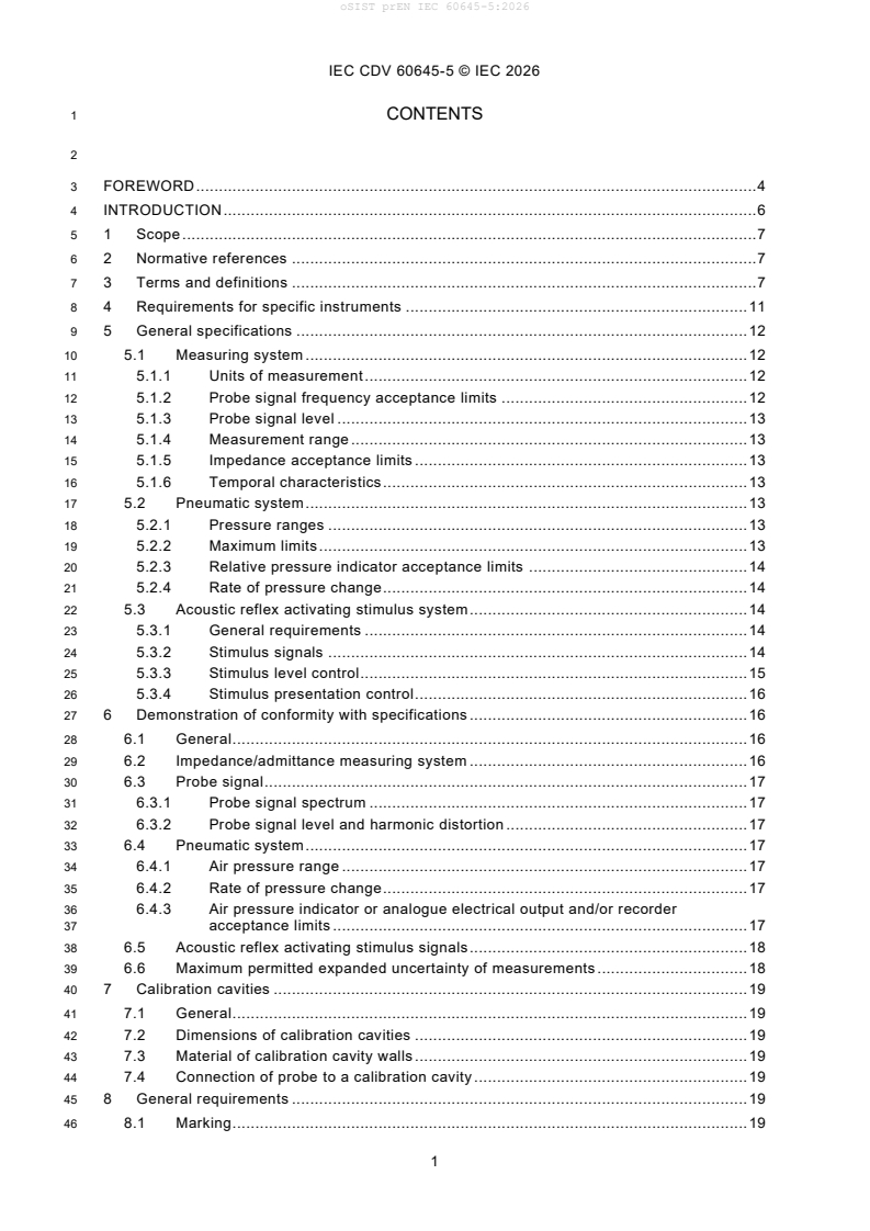
1 CONTENTS
3 FOREWORD . 4
4 INTRODUCTION . 6
5 1 Scope . 7
6 2 Normative references . 7
7 3 Terms and definitions . 7
8 4 Requirements for specific instruments . 11
9 5 General specifications . 12
10 5.1 Measuring system . 12
11 5.1.1 Units of measurement . 12
12 5.1.2 Probe signal frequency acceptance limits . 12
13 5.1.3 Probe signal level . 13
14 5.1.4 Measurement range . 13
15 5.1.5 Impedance acceptance limits . 13
16 5.1.6 Temporal characteristics . 13
17 5.2 Pneumatic system . 13
18 5.2.1 Pressure ranges . 13
19 5.2.2 Maximum limits . 13
20 5.2.3 Relative pressure indicator acceptance limits . 14
21 5.2.4 Rate of pressure change . 14
22 5.3 Acoustic reflex activating stimulus system . 14
23 5.3.1 General requirements . 14
24 5.3.2 Stimulus signals . 14
25 5.3.3 Stimulus level control. 15
26 5.3.4 Stimulus presentation control . 16
27 6 Demonstration of conformity with specifications . 16
28 6.1 General . 16
29 6.2 Impedance/admittance measuring system . 16
30 6.3 Probe signal . 17
31 6.3.1 Probe signal spectrum . 17
32 6.3.2 Probe signal level and harmonic distortion . 17
33 6.4 Pneumatic system . 17
34 6.4.1 Air pressure range . 17
35 6.4.2 Rate of pressure change . 17
36 6.4.3 Air pressure indicator or analogue electrical output and/or recorder
37 acceptance limits . 17
38 6.5 Acoustic reflex activating stimulus signals . 18
39 6.6 Maximum permitted expanded uncertainty of measurements . 18
40 7 Calibration cavities . 19
41 7.1 General . 19
42 7.2 Dimensions of calibration cavities . 19
43 7.3 Material of calibration cavity walls . 19
44 7.4 Connection of probe to a calibration cavity . 19
45 8 General requirements . 19
46 8.1 Marking . 19
IEC CDV 60645-5 © IEC 2026
47 8.2 Instruction manual . 19
48 8.3 Safety requirements . 19
49 8.3.1 General . 19
50 8.3.2 Immunity to power and radio frequency fields . 20
51 8.4 Warm-up time . 20
52 8.5 Supply variation and environmental conditions . 20
53 8.5.1 Mains operation . 20
54 8.5.2 Battery operation . 20
55 8.5.3 Temperature and humidity operating range . 20
56 8.6 Unwanted acoustic signals and radiation. 20
57 8.6.1 Extraneous sound from probe . 20
58 8.6.2 Radiated acoustic noise . 20
59 9 Symbols, forms and formats for acoustic impedance/admittance data . 21
60 9.1 Symbols for indicating measured quantities . 21
61 9.2 Tympanogram format . 21
62 9.2.1 Horizontal axis . 21
63 9.2.2 Vertical axis . 21
64 9.2.3 Scale proportion . 21
65 9.2.4 Probe ear . 21
66 9.3 Acoustic reflex test format . 21
67 9.3.1 Analogue or digital readout . 21
68 9.3.2 Recorder . 22
69 9.3.3 Stimulus ear . 22
70 9.4 Eustachian tube function test format . 22
71 9.4.1 General . 22
72 9.4.2 Horizontal axis . 22
73 9.4.3 Vertical axis . 22
74 10 Additional characteristics to be specified by the manufacturer . 22
75 10.1 Aural impedance/admittance measurement system . 22
76 10.1.1 Influence of ambient temperature, humidity and barometric pressure . 22
77 10.1.2 Probe dimensions . 22
78 10.1.3 Maintenance information . 22
79 10.1.4 Probe signal characteristics . 23
80 10.1.5 Acoustic impedance/admittance indicator . 23
81 10.1.6 Temporal characteristics . 23
82 10.2 Pneumatic system . 23
83 10.2.1 Pressure control system . 23
84 10.2.2 Pressure indicator . 23
85 10.3 Acoustic reflex activating stimulus system . 23
86 10.3.1 General . 23
87 10.3.2 Stimulus level control. 24
88 10.3.3 Stimulus presentation control . 24
89 10.4 Analogue electrical output . 24
90 10.4.1 Pneumatic system . 24
91 10.4.2 Acoustic reflex activating stimulus system . 24
92 10.4.3 Aural impedance/admittance measuring system . 24
93 11 Periodic calibration . 24
94 Annex A (informative) Units and terms . 26
IEC CDV 60645-5 © IEC 2026
95 A.1 Units used for aural impedance/admittance instruments . 26
96 A.2 Suggested terms and definitions . 26
97 Annex B (informative) Overall temporal characteristics . 28
98 Annex C (informative) Relationship between tolerance interval, corresponding
99 acceptance interval and the maximum permitted uncertainty of measurement . 30
101 Figure 1 – Temporal characteristics of an electrical reference tone burst . 11
102 Figure B.1 – Overall temporal characteristics measured in a test cavity in response to
103 step-wise input changes, starting at T . 28
o
104 Figure C.1 – Relationship between tolerance interval, corresponding acceptance
105 interval and the maximum permitted uncertainty of measurement . 30
107 Table 1 – Mandatory functions for aural impedance/admittance instruments . 12
108 Table 2 – Minimum hearing level ranges for different stimuli for Type 1 instruments . 15
109 Table 3 – Values of Umax for measurements . 18
110 Table A.1 – Symbols, units and conversion from c.g.s. to SI . 26
IEC CDV 60645-5 © IEC 2026
114 INTERNATIONAL ELECTROTECHNICAL COMMISSION
115 ____________
117 ELECTROACOUSTICS – AUDIOMETRIC EQUIPMENT –
118 Part 5: Instruments for the measurement of aural acoustic
119 impedance/admittance
122 FOREWORD
123 1) The International Electrotechnical Commission (IEC) is a worldwide organization for standardization comprising
124 all national electrotechnical committees (IEC National Committees). The object of IEC is to promote international
125 co-operation on all questions concerning standardization in the electrical and electronic fields. To this end and
126 in addition to other activities, IEC publishes International Standards, Technical Specifications, Technical Reports,
127 Publicly Available Specifications (PAS) and Guides (hereafter referred to as “IEC Publication(s)”). Their
128 preparation is entrusted to technical committees; any IEC National Committee interested in the subject dealt with
129 may participate in this preparatory work. International, governmental and non-governmental organizations liaising
130 with the IEC also participate in this preparation. IEC collaborates closely with the International Organization for
131 Standardization (ISO) in accordance with conditions determined by agreement between the two organizations.
132 2) The formal decisions or agreements of IEC on technical matters express, as nearly as possible, an international
133 consensus of opinion on the relevant subjects since each technical committee has representation from all
134 interested IEC National Committees.
135 3) IEC Publications have the form of recommendations for international use and are accepted by IEC National
136 Committees in that sense. While all reasonable efforts are made to ensure that the technical content of IEC
137 Publications is accurate, IEC cannot be held responsible for the way in which they are used or for any
138 misinterpretation by any end user.
139 4) In order to promote international uniformity, IEC National Committees undertake to apply IEC Publications
140 transparently to the maximum extent possible in their national and regional publications. Any divergence between
141 any IEC Publication and the corresponding national or regional publication shall be clearly indicated in the latter.
142 5) IEC itself does not provide any attestation of conformity. Independent certification bodies provide conformity
143 assessment services and, in some areas, access to IEC marks of conformity. IEC is not responsible for any
144 services carried out by independent certification bodies.
145 6) All users should ensure that they have the latest edition of this publication.
146 7) No liability shall attach to IEC or its directors, employees, servants or agents including individual experts and
147 members of its technical committees and IEC National Committees for any personal injury, property damage or
148 other damage of any nature whatsoever, whether direct or indirect, or for costs (including legal fees) and
149 expenses arising out of the publication, use of, or reliance upon, this IEC Publication or any other IEC
150 Publications.
151 8) Attention is drawn to the Normative references cited in this publication. Use of the referenced publications is
152 indispensable for the correct application of this publication.
153 9) IEC draws attention to the possibility that the implementation of this document may involve the use of (a)
154 patent(s). IEC takes no position concerning the evidence, validity or applicability of any claimed patent rights in
155 respect thereof. As of the date of publication of this document, IEC had not received notice of (a) patent(s), which
156 may be required to implement this document. However, implementers are cautioned that this may not represent
157 the latest information, which may be obtained from the patent database available at https://patents.iec.ch. IEC
158 shall not be held responsible for identifying any or all such patent rights.
159 IEC 60645-5 has been prepared by IEC technical committee 29: Electroacoustics. It is an
160 International Standard.
161 This second edition cancels and replaces the first edition published in 2004. This edition
162 constitutes a technical revision.
163 This edition includes the following significant technical change with respect to the previous
164 edition:
165 a) updated to comply with the current state of the art within instruments for the measure of
166 aural acoustic impedance/admittance.
IEC CDV 60645-5 © IEC 2026
167 The text of this International Standard is based on the following documents:
Draft Report on voting
XX/XX/FDIS XX/XX/RVD
169 Full information on the voting for its approval can be found in the report on voting indicated in
170 the above table.
171 The language used for the development of this International Standard is English.
172 This document was drafted in accordance with ISO/IEC Directives, Part 2, and developed in
173 accordance with ISO/IEC Directives, Part 1 and ISO/IEC Directives, IEC Supplement, available
174 at www.iec.ch/members_experts/refdocs. The main document types developed by IEC are
175 described in greater detail at www.iec.ch/publications.
176 The committee has decided that the contents of this document will remain unchanged until the
177 stability date indicated on the IEC website under webstore.iec.ch in the data related to the
178 specific document. At this date, the document will be
179 • reconfirmed,
180 • withdrawn, or
181 • revised.
IEC CDV 60645-5 © IEC 2026
183 INTRODUCTION
184 Developments in the field of diagnostic hearing measurement have resulted in a number of
185 instruments designed to evaluate the acoustic impedance/admittance of the human ear by
186 means of acoustic probe signals having different frequencies and temporal characteristics. The
187 practical use of such instruments concerns to a large extent the measurement of changes in
188 acoustic impedance/admittance caused either by varying the air pressure in the external
189 auditory meatus or by activating the middle ear muscle reflex.
190 Conformance to the performance specification in this document is demonstrated when a
191 measured deviation from a design goal equals or does not exceed the corresponding
192 acceptance limit(s), and the laboratory has demonstrated that the associated uncertainty of
193 measurement equals or does not exceed the maximum permitted uncertainty specified in this
194 document.
IEC CDV 60645-5 © IEC 2026
197 1 Scope
198 This part of IEC 60645 applies to instruments designed primarily for the measurement of
199 acoustic impedance/admittance in the human external auditory meatus using a stated probe
200 tone. It is recognized that other probe signals may also be used. This document defines the
201 characteristics to be specified by the manufacturer, lays down performance specifications for
202 three types of instruments and specifies the facilities to be provided on these types. This
203 document describes methods of test to be used for approval testing and guidance on methods
204 for undertaking routine calibration.
205 The purpose of this document is to ensure that measurements made under comparable test
206 conditions with different instruments complying with this document will be consistent. This
207 document is not intended to restrict development or incorporation of new features, nor to
208 discourage innovative approaches.
209 2 Normative references
210 The following documents are referred to in the text in such a way that some or all of their content
211 constitutes requirements of this document. For dated references, only the edition cited applies.
212 For undated references, the latest edition of the referenced document (including any
213 amendments) applies.
214 IEC 60318 (all parts), Electroacoustics – Simulators of human head and ear
215 IEC 60318-4, Electroacoustics – Simulators of human head and ear - Part 4: Occluded-ear
216 simulator for the measurement of earphones coupled to the ear by means of ear inserts
217 IEC 60318-5, Electroacoustics – Simulators of human head and ear - Part 5: 2 cm coupler for
218 the measurement of hearing aids and earphones coupled to the ear by means of ear inserts
219 IEC 60601-1, Medical electrical equipment – Part 1: General requirements for basic safety and
220 essential performance
221 IEC 60601-1-2, Medical electrical equipment – Part 1-2: General requirements for basic safety
222 and essential performance - Collateral Standard: Electromagnetic disturbances - Requirements
223 and tests
224 IEC 60645-1:2017, Electroacoustics – Audiometric equipment – Part 1: Equipment for pure tone
225 and speech audiometry
226 ISO 389-1, Acoustics – Reference zero for the calibration of audiometric equipment – Part 1:
227 Reference equivalent threshold sound pressure levels for pure tones and supra-aural
228 earphones
229 ISO 389-2, Acoustics – Reference zero for the calibration of audiometric equipment – Part 2:
230 Reference equivalent threshold sound pressure levels for pure tones and insert earphones
231 ISO/IEC Guide 98-3, Uncertainty of measurement – Part 3: Guide to the expression of
232 uncertainty in measurement (GUM:1995)
233 ISO/IEC Guide 98-4, Uncertainty of measurement – Part 4: Role of measurement uncertainty in
234 conformity assessment (ISO/IEC 2012)
235 3 Terms and definitions
236 For the purposes of this document, the following terms and definitions apply.
IEC CDV 60645-5 © IEC 2026
237 ISO and IEC maintain terminology databases for use in standardization at the following
238 addresses:
239 • IEC Electropedia: available at https://www.electropedia.org/
240 • ISO Online browsing platform: available at https://www.iso.org/obp
241 3.1
242 aural impedance/admittance
243 general term covering all aspects of acoustic impedance/admittance of the ear
244 Note 1 to entry: Throughout this document the term aural impedance/admittance will be employed as a general term
245 covering all aspects of acoustic impedance/admittance of the ear, except where reference is made to specific
246 derivatives.
247 3.2
248 acoustic impedance
249 at a specified surface, quotient of sound pressure by volume velocity through the surface
250 Note 1 to entry: The symbol is Z and the unit is pascal second per metre to the third power (Pas/m ).
a
251 Note 2 to entry: The quantity usually measured is the modulus.
252 3.3
253 acoustic admittance
254 at a given surface, the reciprocal of acoustic impedance at the same surface
255 Note 1 to entry: The symbol is Y and the unit is the metre to the third power per pascal second (m /Pas).
a
256 Note 2 to entry: Thus, the acoustic admittance at a given surface is the complex ratio of the volume velocity through
257 the surface to sound pressure averaged over the surface. The quantity usually measured is the modulus.
258 3.4
259 acoustic resistance
260 real component of complex acoustic impedance
261 Note 1 to entry: The symbol is R and the unit is the pascal second per metre to the third power (Pas/m ).
a
262 3.5
263 acoustic reactance
264 imaginary component of complex acoustic impedance
265 Note 1 to entry: The symbol is X and the unit is the pascal second per metre to the third power (Pas/m ).
a
266 3.6
267 acoustic conductance
268 real component of complex acoustic admittance
269 Note 1 to entry: The symbol is G and the unit is the metre to the third power per pascal second (m /Pas).
a
270 3.7
271 acoustic susceptance
272 imaginary component of complex acoustic admittance
273 Note 1 to entry: The symbol is B and the unit is the metre to the third power per pascal second (m /Pas).
a
274 3.8
275 acoustic compliance
276 ratio of volume displacement to sound pressure
277 Note 1 to entry: The symbol is C and the unit is the metre to third power per pascal (m /Pa).
a
IEC CDV 60645-5 © IEC 2026
279 3.9
280 equivalent volume
281 volume of an air-filled hard-walled cylindrical cavity that offers the equivalent acoustic
282 impedance/admittance
283 Note 1 to entry: The volume is given by the formula:
284 V = p C = c C
e s a a
285 where
286 V is the equivalent volume in m ;
e
287 is the ratio of specific heat for air at constant pressure to that at constant volume (approximately 1,40);
288 p is the barometric air pressure in Pa;
s
289 is the ambient density of air in kg/m , at the temperature and pressure of the measurement;
290 c is the speed of sound in m/s at the temperature and pressure of the measurement;
291 C is the acoustic compliance in m /Pa.
a
292 Note 2 to entry: It has been practice to refer to aural impedance/admittance at the probe tone frequency of 226 Hz
293 as an equivalent volume of air.
294 Note 3 to entry: For a probe tone frequency of 226 Hz, the equivalent volume of air is equal to its physical volume
295 provided the latter does not exceed 5 cm .
296 3.10
297 relative pressure in the external auditory meatus
298 difference between the pressure in the external auditory meatus and the ambient barometric air
299 pressure in daPa
300 3.11
301 probe
302 coupling device that is inserted into the external auditory meatus to connect the instrument to
303 the ear
304 3.12
305 ear tip
306 device used to provide a seal between the probe and the external auditory meatus
307 3.13
308 probe signal
309 acoustic signal that is emitted into the external auditory meatus by means of a probe
310 Note 1 to entry: The signal is used to measure acoustic impedance/admittance.
311 3.14
312 probe ear
313 ear into which the probe is inserted
314 3.15
315 measurement plane
316 plane located at the frontal surface of the probe perpendicular to the volume velocity vector
IEC CDV 60645-5 © IEC 2026
318 3.16
319 tympanometry
320 measurement of change of aural impedance/admittance as a function of air pressure in the
321 external auditory meatus
322 Note 1 to entry: The measured acoustic impedance/admittance values may depend on rate and direction of change
323 of air pressure as well as time spent with a certain constant air pressure in the external auditory meatus.
324 3.16.1
325 measurement plane tympanometry
326 measurement of change of the aural impedance/admittance at the measurement plane,
327 comprising the combined impedance/admittance of the middle ear and part of the external
328 auditory meatus
329 3.16.2
330 meatus-compensated tympanometry
331 measurement of the vector difference between the aural impedance/admittance obtained at the
332 test pressure and that obtained at a specific reference pressure in the external auditory meatus
333 for a given fitting of the probe
334 Note 1 to entry: The reference pressure should be such as to effectively eliminate the influence of the middle ear.
335 Note 2 to entry: The reference pressure will normally be 200 daPa different from the indicated pressure, which gives
336 maximum admittance or minimum impedance indication, or fixed at 200 daPa relative to ambient pressure.
337 3.17
338 tympanogram
339 graphical display of some quantity related to aural impedance/admittance as a function of air
340 pressure in the external auditory meatus
341 3.18
342 middle-ear muscle reflex
343 change in tonus of muscles of the middle ear in response to stimulation
344 Note 1 to entry: The change may be measured as a variation in the acoustic impedance/admittance within the external
345 auditory meatus
346 3.18.1
347 acoustic reflex
348 middle-ear muscle reflex elicited by an acoustic stimulus
349 3.18.2
350 non-acoustic reflex
351 middle-ear muscle reflex elicited by a non-acoustic stimulus
352 3.19
353 acoustic reflex activating stimulus
354 acoustic stimulus that is used to elicit an acoustic reflex
355 3.20
356 stimulus ear
357 ear to which a reflex activating stimulus is presented in order to elicit a middle ear muscle reflex
358 3.21
359 ipsilateral reflex
360 middle ear muscle reflex elicited in the stimulus ear
IEC CDV 60645-5 © IEC 2026
361 3.22
362 contralateral reflex
363 middle ear muscle reflex elicited in the ear contralateral to the stimulus ear
364 3.23
365 tone burst
366 gated sinusoidal signal having a duration of less than 200 ms
370 Key
371 1 level
372 2 time
373 3 rise time
374 4 duration
375 5 fall time
376 Figure 1 – Temporal characteristics of an electrical reference tone burst
377 3.24
378 sound pressure level
379 sound pressure level (SPL) is ten times the logarithm to the base 10 of the ratio of the square
380 of the sound pressure, p, to the square of a reference value, p0, expressed in decibels (dB),
381 where the reference value p , is 20 μPa.
382 4 Requirements for specific instruments
383 Three different types of aural acoustic impedance/admittance instruments are specified by the
384 requirements for minimum mandatory facilities (see Table 1). Other facilities are not precluded.
385 The three types relate to their presumed primary application.
IEC CDV 60645-5 © IEC 2026
387 Table 1 – Mandatory functions for aural impedance/admittance instruments
Type
1 2 3
Diagnostic Tympanometry and Tympanometry
reflex screening screening
Probe signal frequency 226 Hz x x x
Aural impedance/admittance measuring system
Measurement plane tympanometry a a a
x x x
Meatus compensated tympanometry a a a
x x x
Pneumatic system
Manual change of pressure x
Automatic change of pressure x x x
Acoustic reflex activating system
Ipsilateral x x
Contralateral x
Acoustic stimuli:
b b
Pure tones
x x
Tone burst b b
x x
Broadband noise x
Stimulus level control x
Presentation of results
c x x x
Display or visual indicator
Data interfacing, data storage, and export/print of x x
test results
a,b
Indicating that at least one of the two alternatives shall be provided.
c
Display or visual indicator may be on the device itself or any connected computer or device.
389 5 General specifications
390 5.1 Measuring system
391 5.1.1 Units of measurement
392 The instruments may be designated to measure one or more components of aural
393 impedance/admittance. SI units or derived SI units shall be used. The units of measurement
394 shall be indicated in the display of the measurement data.
395 5.1.2 Probe signal frequency acceptance limits
396 A probe signal in the form of a pure tone with a frequency of 226 Hz shall be provided in
397 instruments of Types 1, 2 and 3. The actual frequency shall differ from its nominal frequency
398 by less than 1 % for Type 1 instruments and by less than 2 % for Types 2 and 3. The total
399 harmonic distortion shall be less than 1 % for Type 1 and less than 3 % for Types 2 and 3, when
400 measured as specified in Clause 6. If pure tones of frequencies other than 226 Hz are available,
401 the same requirements with regard to frequency acceptance limits and harmonic distortion shall
402 apply.
403 When tests such as multi-frequency tympanometry are performed which require frequency
404 acceptance limits better than the 1 % specified, the manufacturer shall state the acceptance
405 limits of the frequency used for that test.
IEC CDV 60645-5 © IEC 2026
406 5.1.3 Probe signal level
407 For pure tones of any frequency, for stationary broadband and for non-stationary probe signals
408 the level shall be such that the probability of activating the middle ear muscle reflex by the
409 probe signal is acceptably small. This corresponds to a probe signal sound pressure level that
410 is less than the mean value, minus two standard deviations, for the threshold level of the
411 acoustic middle ear reflex. The threshold must be obtained in a sufficiently large, otologically
412 normal, young adult population when the probe signal is used as a reflex activating stimulus (a
413 population of 25 persons is considered to be sufficiently large).
414 For a 226 Hz pure tone probe signal, the sound pressure level shall be 90 dB or less as
415 measured according to Clause 6.
416 NOTE 1 An otologically normal person is defined in ISO 389-1:2017, clause 3.5.
417 5.1.4 Measurement range
418 For a 226 Hz probe tone the minimum ranges expressed as equivalent volume of air shall be:
3 3
419 for measurement plane tympanometry, from 0,2 cm to 5 cm ; for meatus compensated
3 3 3 3
420 tympanometry, from 0 cm to 2 cm in Types 1 and 2, and from 0 cm to 1,2 cm in Type 3
421 instruments.
422 The manufacturer shall state the sensitivity for the acoustic reflex measuring system and the
423 stimulus level at which there is a possibility of artefactual change occurring in the measurement
424 display synchronously with the presentation of the reflex eliciting stimulus.
425 NOTE 1 Measurement of artefact on a hard-walled cavity does not necessarily represent the conditions that occur
426 in human ears. Therefore, no method of measurement of artefacts in human ears is specified.
427 5.1.5 Impedance acceptance limits
428 The difference between indicated and actual impedance/admittance values shall not exceed
3 –9 3
429 5 % or 0,1 cm of the equivalent volume, or 10 m /Pas, whichever is greater. The
430 manufacturer shall state the deviation between the static and the dynamic mode of operation
431 and the method of measurement.
432 5.1.6 Temporal characteristics
433 The various temporal response parameters are defined in 10.1.6. The temporal characteristics
434 shall not exceed 50 ms and overshoot and undershoot shall not exceed 10 %.
435 NOTE 1 At probe tone frequencies higher than 226 Hz, shorter response times are desirable.
436 5.2 Pneumatic system
437 5.2.1 Pressure ranges
438 For instruments of Type 1, the range of relative pressure shall be at least from +200 daPa to -
439 600 daPa.
440 For instruments of Type 2 and 3, the range shall be at least from +200 daPa to -200 daPa.
441 5.2.2 Maximum limits
442 The maximum permissible limits of relative pressure are -800 daPa and +600 daPa and shall
443 be measured in a 0,5 cm cavity. These limits shall apply to all types of instruments. All
444 instruments shall have a means which will prevent the pressure from suddenly reaching, or
445 exceeding these limits.
IEC CDV 60645-5 © IEC 2026
446 5.2.3 Relative pressure indicator acceptance limits
447 For instruments of Type 1, the actual relative pressure produced by the instrument in cavities
3 3
448 from 0,5 cm to 5 cm shall not differ from the indicated relative pressure by more than
449 10 daPa or 10 %, whichever is the greater.
450 For instruments of Types 2 and 3, the actual relative pressure produced by the instrument in
3 3
451 cavities from 0,5 cm to 2 cm shall not differ from the indicated relative pressure by more than
452 10 daPa or 15 %, whichever is greater.
453 These specifications shall be met for the rates of changes of pressure provided.
454 5.2.4 Rate of pressure change
455 The manufacturer shall specify the minimum and maximum rates of pressure change in a 2 cm
456 cavity. In addition, Type 1 instruments shall at least provide a rate of pressure change of
3 3
457 50 daPa/s 10 daPa/s, measured in cavities from 0,5 cm to 5,0 cm .
458 5.3 Acoustic reflex activating stimulus system
459 5.3.1 General requirements
460 Specifications for the acoustic reflex activating stimulus system are as given in the relevant
461 clauses of IEC 60645-1:2017 for Test signals, Signal level control, and Calibration, with the
462 exceptions given in Clause 5.3 of this document.
463 5.3.2 Stimulus signals
464 5.3.2.1 General
465 Type 1 instruments shall provide either pure tone or tone burst signals of at least 500 Hz,
466 1 000 Hz, 2 000 Hz and 4 000 Hz stimuli for both contralateral and ipsilateral acoustic reflex
467 stimulation and measurements.
468 Type 2 instruments shall provide either pure tone or tone burst signals of the frequencies
469 500 Hz, 1 000 Hz or 2 000 Hz stimuli for ipsilateral acoustic reflex stimulation and
470 measurements.
471 The frequency shall not deviate by more than 1 % for Type 1 instruments and 3 % for Type 2
472 instruments.
473 5.3.2.2 Pure tone harmonic distortion
474 For the frequencies and stimulus level settings listed in Table 2, the total harmonic distortion of
475 the test tone shall not exceed 2,5 % for supra-aural earphones and 5 % for insert or probe-type
476 earphones for hearing levels up to 110 dB in the frequency range 500 Hz to 4 000 Hz. At higher
477 level settings the maximum level of harmonics shall not exceed 5 % total harmonic distortion
478 for supra-aural earphones, and 10 % total harmonic distortion for insert or probe-type
479 earphones.
480 If the maximum output for an instrument corresponds to a hearing level of less than 110 dB, the
481 requirement given shall apply to the maximum output levels of the instruments.
482 5.3.2.3 Broadband noise
483 If a broadband (random) noise is provided, it shall have a frequency response as measured
484 acoustically, which meets the following requirements.
IEC CDV 60645-5 © IEC 2026
485 For supra-aural earphone, the acceptance limit shall be 5 dB relative to the 1 000 Hz level
486 over the frequency range of 500 Hz to 4 000 Hz.
487 For the insert or probe-type earphone, the acceptance limit shall be 10 dB relative to the
488 1 000 Hz level over the frequency range of 500 Hz to 4 000 Hz.
489 5.3.2.4 Other stimuli
490 If other types of stimuli are provided, the manufacturer shall describe the characteristics of such
491 stimuli.
492 5.3.3 Stimulus level control
493 5.3.3.1 Markings
494 Instruments calibrated to this document shall be identified either on the front panel or on the
495 stimulus level control. The signal level control shall be identified by the designation "Hearing
496 Level" (HL) or an equivalent national designation. The zero marking on the hearing level control
497 shall correspond to an output from the transducer which relates to the reference equivalent
498 values given in the relevant parts of ISO 389. If other transducers or other reference levels than
499 those listed in the relevant parts of ISO 389 are used, the manufacturer shall state the origins
500 and basis of the reference levels, together with the procedures and ear simulators or couplers
501 to be used for calibration. The maximum level setting for each frequency and for the broad -
502 band noise shall be indicated.
503 5.3.3.2 Intervals and minimum range
504 For instruments of Type 1, the stimulus level control shall cover at least the range listed in Table
505 2. Readings of the stimulus level shall be indicated in intervals of 5 dB or less.
506 For instruments of Type 2, the stimulus level may be fixed and shall be specified by the
507 manufacturer.
508 Table 2 – Minimum hearing level ranges for different stimuli for Type 1 instruments
Stimulus 500 Hz to 2 000 Hz 4 000 Hz Noise
a
Hearing level range for supra-aural earphones
50 – 120 50 – 120 50 – 115
in dB
a
Hearing level range for insert or probe-type
50 – 100 50 – 80 50 – 90
earphones in dB
a
In case of noise the range may alternatively be specified in terms of sound pressure levels.
510 NOTE 1 In children, stimulus levels in the external auditory meatus may be higher than indicated on the stimulus
511 level control.
512 5.3.3.3 Stimulus level control acceptance limits
513 The sound pressure level produced by the stimulus transducer shall not differ by more than
514 3 dB from the indicated values at any setting of the stimulus level control at indicated
515 frequencies in
...