


EN 13964:2004
(Main)Suspended ceilings - Requirements and test methods
General Information
- Abstract
The European Standard provides information for the various parties responsible for designing, manufacturing and specifying/selecting suspended ceilings used for interior applications in general building and civil engineering structures. It covers suspended ceilings sold as a complete kit (including, optionally, light fittings and other features), substructures sold as kits, individual components (products) of such substructures, and membrane components. It includes test methods and methods of assessment, as well as provisions for the evaluation of conformity of the products to the requirements of this standard.
In the absence of any other European Standard, this standard specifies dimensions, tolerances and, where relevant, performance requirements, for commonly available ceiling substructures and membrane components.
- Status
- Withdrawn
- Publication Date
- 09-Mar-2004
- Withdrawal Date
- 11-Mar-2014
- Technical Committee
- CEN/TC 277 - Suspended ceilings
- Drafting Committee
- CEN/TC 277 - Suspended ceilings
- Current Stage
- 9960 - Withdrawal effective - Withdrawal
- Start Date
- 12-Mar-2014
- Completion Date
- 12-Mar-2014
- Directive
- Harmonized Standard305/2011 - Regulation (eu) No 305/2011 of the European Parliament and of the Council of 9 march 2011 laying down harmonised conditions for the marketing of construction products and repealing council directive 89/106/eec
Not Harmonized89/106/EEC - Construction productsOJ Ref: C, C 139, C 263, C 319 OJ Date: 26-Oct-2004

Relations
- Effective Date
- 19-Mar-2014
- Effective Date
- 25-Aug-2026
- Effective Date
- 25-Aug-2026
- Refers
ISO 7724-3:1984 - Paints and varnishes — Colorimetry — Part 3: Calculation of colour differences - Effective Date
- 25-Aug-2026
- Effective Date
- 22-Jul-2026
- Refers
EN 1998-1-2:2026 - Eurocode 8 - Design of structures for earthquake resistance - Part 1-2: Buildings - Effective Date
- 25-Mar-2026
- Effective Date
- 25-Mar-2026
- Effective Date
- 25-Mar-2026
- Effective Date
- 04-Feb-2026
- Effective Date
- 28-Jan-2026
- Effective Date
- 28-Jan-2026
- Effective Date
- 28-Jan-2026
- Effective Date
- 28-Jan-2026
- Effective Date
- 28-Jan-2026
- Effective Date
- 28-Jan-2026
Get Certified
Connect with accredited certification bodies for this standard

DIBt (Deutsches Institut für Bautechnik)
German Institute for Building Technology.
DIN CERTCO
DIN Group product certification.

Aboma Certification B.V.
Specialized in construction, metal, and transport sectors.
Sponsored listings
Frequently Asked Questions
EN 13964:2004 is a standard published by the European Committee for Standardization (CEN). Its full title is "Suspended ceilings - Requirements and test methods". This standard covers: The European Standard provides information for the various parties responsible for designing, manufacturing and specifying/selecting suspended ceilings used for interior applications in general building and civil engineering structures. It covers suspended ceilings sold as a complete kit (including, optionally, light fittings and other features), substructures sold as kits, individual components (products) of such substructures, and membrane components. It includes test methods and methods of assessment, as well as provisions for the evaluation of conformity of the products to the requirements of this standard. In the absence of any other European Standard, this standard specifies dimensions, tolerances and, where relevant, performance requirements, for commonly available ceiling substructures and membrane components.
The European Standard provides information for the various parties responsible for designing, manufacturing and specifying/selecting suspended ceilings used for interior applications in general building and civil engineering structures. It covers suspended ceilings sold as a complete kit (including, optionally, light fittings and other features), substructures sold as kits, individual components (products) of such substructures, and membrane components. It includes test methods and methods of assessment, as well as provisions for the evaluation of conformity of the products to the requirements of this standard. In the absence of any other European Standard, this standard specifies dimensions, tolerances and, where relevant, performance requirements, for commonly available ceiling substructures and membrane components.
EN 13964:2004 is classified under the following ICS (International Classification for Standards) categories: 91.060.30 - Ceilings. Floors. Stairs. The ICS classification helps identify the subject area and facilitates finding related standards.
EN 13964:2004 has the following relationships with other standards: It is inter standard links to EN 13964:2014, ISO 7724-2:1984, ISO 1006:1983, ISO 7724-3:1984, EN 312:2010, EN 1998-1-2:2026, EN 573-3:2026, EN 1991-1-4:2026, EN ISO 11925-2:2026, EN 622-1:2003, EN ISO 12460-3:2023, EN 10346:2015, EN 1993-1-9:2025, EN 1998-1-1:2024, EN 1396:1996. Understanding these relationships helps ensure you are using the most current and applicable version of the standard.
EN 13964:2004 is associated with the following European legislation: EU Directives/Regulations: 305/2011, 89/106/EEC; Standardization Mandates: M/121. When a standard is cited in the Official Journal of the European Union, products manufactured in conformity with it benefit from a presumption of conformity with the essential requirements of the corresponding EU directive or regulation.
EN 13964:2004 is available in PDF format for immediate download after purchase. The document can be added to your cart and obtained through the secure checkout process. Digital delivery ensures instant access to the complete standard document.
Standards Content (Sample)
2003-01.Slovenski inštitut za standardizacijo. Razmnoževanje celote ali delov tega standarda ni dovoljeno.Suspended ceilings - Requirements and test methodsPlafonds suspendus - Exigences et méthodes d'essaiUnterdecken - Anforderungen und Prüfverfahren91.060.30Stropi. Tla. StopniceCeilings. Floors. StairsICS:SIST EN 13964:2004enTa slovenski standard je istoveten z:EN 13964:200401-junij-2004SIST EN 13964:2004SLOVENSKI
STANDARD
EUROPEAN STANDARDNORME EUROPÉENNEEUROPÄISCHE NORMEN 13964March 2004ICS 91.060.30English versionSuspended ceilings - Requirements and test methodsPlafonds suspendus - Exigences et méthodes d'essaiUnterdecken - Anforderungen und PrüfverfahrenThis European Standard was approved by CEN on 3 November 2003.CEN members are bound to comply with the CEN/CENELEC Internal Regulations which stipulate the conditions for giving this EuropeanStandard the status of a national standard without any alteration. Up-to-date lists and bibliographical references concerning such nationalstandards may be obtained on application to the Management Centre or to any CEN member.This European Standard exists in three official versions (English, French, German). A version in any other language made by translationunder the responsibility of a CEN member into its own language and notified to the Management Centre has the same status as the officialversions.CEN members are the national standards bodies of Austria, Belgium, Cyprus, Czech Republic, Denmark, Estonia, Finland, France,Germany, Greece, Hungary, Iceland, Ireland, Italy, Latvia, Lithuania, Luxembourg, Malta, Netherlands, Norway, Poland, Portugal, Slovakia,Slovenia, Spain, Sweden, Switzerland and United Kingdom.EUROPEAN COMMITTEE FOR STANDARDIZATIONCOMITÉ EUROPÉEN DE NORMALISATIONEUROPÄISCHES KOMITEE FÜR NORMUNGManagement Centre: rue de Stassart, 36
B-1050 Brussels© 2004 CENAll rights of exploitation in any form and by any means reservedworldwide for CEN national Members.Ref. No. EN 13964:2004 E
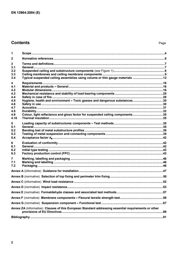
Guidance for installation.47Annex B (normative)
Selection of top fixing and perimeter trim fixing.50Annex C (informative)
Wind load resistance.52Annex D (normative)
Impact resistance.53Annex E (normative)
Formaldehyde classes and associated test methods.57Annex F (normative)
Membrane components – Flexural tensile strength test.59Annex G (normative)
Suspension component – Functional test.67Annex ZA (informative)
Clauses of this European Standard addressing essential requirements or otherprovisions of EU Directives.69Bibliography.81
Parallel to bottom flange+ 0,3-
0,3+ 0,3-
0,3+ 0,3-
0,3-+ 1,50-
1,50Bandraster+ 0,3- 0,3+ 0,3- 0,3-+ 0,3- 0,3+ 30- 30Furring channel+ 0,3- 0,3--+ 0,3- 0,3+ 30- 30Perimeter trims+ 0,5- 0,5--+ 0,3- 0,3+ 00- 30NOTE 1Measurements in mm are related to the manufactured sizeNOTE 2 nominal = 90°
Interlocking holes in section2
Splice in supporting componentDefinition:X : 1 Slot distanceY : Sum of slot distances
1,25 m including or excluding one spliceTolerance:X : + / - 0,25 mmY : + / - 0,30 mmCentre point substructureDefinition:M : Axis- axis distance between 2 main runnersX : Axis- axis distance between 2 cross teesTolerance:M : + / - 0,25 mm / mX : + / - 0,25 mm
03,0-mm-for width
04,0-mmb. Flatness :Key1
Tolerance b2
Tolerance al = length (mm)0 < l
1000 < l 20002000 < l
3000b = width (mm)ababab
0 < b
400400 <
b
500500 <
b
625625 <
b
1 250- 0,5+0,5- 0,5+0,5- 0,5+0,5- 0,5+0,5- 0,2+3,0- 0+4,0- 0+6,0- 0+10,0- 0,5+1,5- 0,5+1,5- 0,5+1,5- 0,5+1,5- 0,2+4,0- 0+5,0- 0+7,0- 0+13,0- 0,5+3,0- 0,5+3,5- 0,5+4,0--- 0,2+6,0- 0+7,0- 0+9,0--c.Angularity of the long edge in relation to short edgePanel width up to 625 mm
± 0,5 mmPanel width 625 mm to 1 250 mm
± 0,6 mmd.Depth of stops / supports ± 0,3 mm (measured on panel cut out edge)
Edge
Cut-out edgeDeviations from 90° angle on vertical upstand are dependent on the production process and the relative suspensionsystems. There are no fixed tolerances.Width 300mm
Load bearing structure
Linear component2
Top fixing
Perimeter trim3
Suspension
System height4
Supporting memberKey1
Load bearing structure
Linear component width2
Top fixing
Joint3
Suspension
Linear component module4
Supporting member
Join profile5
System height
Linear component
+ / - 0,5Component length (850 < 3 000) mm + / - 1,25
(3 000 Component width
+ / - 0,75Due to material and production propertiesadditional dimensional tolerances occur becauseof spring-back at the panel endsKeyA
Linear component lengthB
Linear component widthC
Linear component heightPlane and waves (dimensions in mm)PlaneKey1
Tolerance C2
Tolerance DKeyA
Linear component lengthB
Linear component widthLinear component width (in mm)0 < b 100 < b 200 < b 300 < b CCCC- 1,0- 1,25- 1,5- 1,75+ 1,5+ 2,0+ 2,5+ 2,7DDDD- 1,5- 2,5-3,5-4,0+ 1,5+ 2,0+2,5+2,7Concave = -Convex = +
Linear component spanLinear component width (in mm)0 < b 200 < b ABAB- 0,5+ 0,5- 0,8+ 0,8CamberThe deviation is maximum 1/1 500 ´ linear component length, measured in the middle of the length of the linear component(equals 0,67mm over 1,0m length).Deflection of the linearcomponentsThe maximum deflection between twosupporting members/ points of supportis 1/500 ´ supporting member distance,measured in the middle between thesupporting members/ points of support.Key1
Supporting member distance (linear component span)2
Supporting member3
Linear component4
Linear component deflection ( 1/500 ´ supporting member distance)Tolerance of the supporting member moduleThe tolerance of the supporting member module is ± 0,06 mm on a linear component module of 100 mm.
Supporting member length = X x Module – cutting toleranceB
Modular length supporting memberC
Supporting members' module1
Module tolerance2
Length tolerance3
Cutting toleranceDeflection of the supportingmembersThe maximum deflection of the supportingmembers between two suspension pointsis 1/500 x suspension distance, measuredin the middle between two suspensionpoints (Class 1, Table 6)Key1
Suspension distance (supporting member span)2
Supporting member deflection3
Linear component4
Supporting member5
Suspension4.3 Mechanical resistance and stability of load bearing components4.3.1 GeneralThis clause of the standard covers only the load bearing components of the suspended ceiling and ceiling lining. Itdoes not cover the mechanical characteristics of membrane components, for which see 4.6.2.The design of the suspended ceiling shall be made so that the admissible building tolerances (limits of buildingtolerances) and the movement and deflection of the adjoining building assemblies (elements) are considered.The stability of the suspended ceiling and / or the ceiling lining respectively shall not be reduced (disturbed) as aresult of the movement of adjoining building elements.In the case of partitions fixed to the suspended ceiling, the forces imposed by the partition shall be carried either bysuitable structural measures or transmitted by the suspended ceiling to the building structure.NOTEMost suspended ceilings are not designed to support the additional load imposed by a partition. In case partitionsare fixed to the suspended ceilings, only ceilings specifically designed for this purpose should be used.
1LB / 500 and not greater than 4,02LB / 3003No limitAThe maximum deflection is the accumulative value of the deflection of the substructure component and the deflection of themembrane componentBL is the span in mm between the suspension components or the suspension points4.3.2.2 Substructure materials4.3.2.2.1 Steel substructureWhere the substructure is formed in hot-galvanised strip or sheet of unalloyed steel, the minimum steel grade usedshall be DX 51D + Z according to EN 10142.If other steel types are used, they shall conform to either EN 10152 (ZE), EN 10169-1, EN 10214 (ZA) or EN 10215(AZ), as appropriate.The thickness tolerance shall be in accordance with EN 10143.For corrosion protection the minimum protection shall be in accordance with Table 8 related to the class ofexposure (see Table 7) to be encountered.4.3.2.2.2 Aluminium substructureWhere substructure members are made of aluminium alloy, the alloy shall be in accordance with EN 573-3 andhave 0,2 % yield strength of at least 160 N/mm2.For corrosion protection, the minimum protection shall be that given in Table 8.
...