


prEN 1995-1-3
(Main)Eurocode 5 - Design of timber structures - Part 1-3: Timber-concrete composite structures
General Information
- Abstract
(1) EN 1995-1-3 gives design rules for timber-concrete composite structures.
(2) EN 1995-1-3 provides requirements for materials, design parameters, connections, detailing and execution for timber-concrete composite structures.
NOTE: Recommendations for environmental parameters (temperature and moisture content), design methods and test methods are given in Annexes.
(3) EN 1995-1-3 covers the design of timber-concrete composite structures in both quasi-constant and variable environmental conditions. It provides design rules for quasi-constant environmental conditions rules for variable environmental conditions.
(4) EN 1995-1-3 excludes details for the design of glued timber-concrete composites and systems relying on friction.
NOTE: For design of bridges see EN 1995-2.
- Status
- Not Published
- Publication Date
- 07-Sep-2027
- Technical Committee
- CEN/TC 250 - Structural Eurocodes
- Drafting Committee
- CEN/TC 250/SC 5/WG 2 - Timber concrete composites
- Current Stage
- 4060 - Closure of enquiry - Enquiry
- Start Date
- 16-Jul-2026
- Due Date
- 15-Oct-2025
- Completion Date
- 16-Jul-2026

Overview
prEN 1995-1-3:2026, developed by the European Committee for Standardization (CEN), is a pivotal document in the Eurocode 5 series, titled "Design of timber structures – Part 1-3: Timber-concrete composite structures." This European Standard provides comprehensive design rules, material requirements, and execution provisions for timber-concrete composite structures, addressing the needs of designers, manufacturers, contractors, and relevant authorities involved in the construction and assessment of hybrid timber-concrete systems.
The standard is applicable to buildings and civil engineering works, focusing on ensuring safety, functionality, and long-term performance under both quasi-constant and variable environmental conditions. It serves as a foundation for creating sustainable and robust composite structures that leverage the benefits of both timber and concrete.
Key Topics
- General Design Principles: prEN 1995-1-3 outlines the fundamental concepts, including limit state design, load combinations, and long-term behavior considerations for timber-concrete composite structures.
- Material Requirements: The standard addresses properties and selection criteria for timber, concrete, reinforcement, and connectors, referencing relevant product standards to ensure quality and performance.
- Connections and Detailing: Detailed provisions are provided for the design and verification of mechanical connections (e.g., dowel-type fasteners, notches, plates), which are critical for composite action and load transfer.
- Environmental Parameters: Recommendations relating to the influence of temperature and moisture content, including yearly variations and their effects on structural reliability, are provided through informative annexes.
- Verification Methods: Approaches to verify resistance, durability, serviceability, deflection, vibration, and cracking are covered, utilizing analytical and test-based methods.
- Limitations: The standard excludes glued timber-concrete composites and structures dependent on friction for load transfer and does not cover the design of bridges, for which EN 1995-2 applies.
Applications
prEN 1995-1-3:2026 applies to a wide range of construction projects where timber and concrete elements are combined to form composite structures. Practical application areas include:
- Building Construction: Floors, slabs, beams, and walls in residential, commercial, and industrial buildings, providing improved strength, stiffness, and overall sustainability.
- Civil Engineering Works: Applications where hybrid structural solutions are preferred for their material efficiency and enhanced performance, especially under variable climate conditions.
- Renovation and Upgrading: Strengthening of existing timber or concrete buildings through retrofitting with composite systems in compliance with modern safety standards.
- Design for Variable Environments: Structures exposed to fluctuating temperature and humidity, such as outdoor balconies and unheated spaces, are specifically addressed with adaptive design rules.
- Quality Control and Testing: Guidance on the testing of composite connections and the use of test methods to determine mechanical properties and serviceability limits.
Related Standards
To ensure consistency and compatibility, prEN 1995-1-3 should be used alongside several key European Standards:
- EN 1990: Basis of structural and geotechnical design
- EN 1991: Actions on structures
- EN 1992: Design of concrete structures
- EN 1994: Design of composite steel and concrete structures (for synergy)
- EN 1995-1-1: General rules for timber structures
- EN 1995-2: Design of timber bridges
- EN 1995-3: Execution of timber structures
- EN 14592: Timber structures – Dowel-type fasteners – Requirements
These related standards ensure a harmonized approach to design, material selection, and construction methods for timber-concrete composite structures across Europe.
In summary: prEN 1995-1-3:2026 provides essential rules and guidance for the safe and effective design of timber-concrete composite structures, supporting sustainable construction with clear requirements for materials, detailing, and verification methods under diverse environmental conditions. This standard helps professionals achieve compliant and high-performance hybrid structures, with strong links to other key Eurocodes and materials standards.
Relations
- Effective Date
- 04-Sep-2024
Get Certified
Connect with accredited certification bodies for this standard

DIBt (Deutsches Institut für Bautechnik)
German Institute for Building Technology.
DIN CERTCO
DIN Group product certification.

Aboma Certification B.V.
Specialized in construction, metal, and transport sectors.
Sponsored listings
Frequently Asked Questions
prEN 1995-1-3 is a draft published by the European Committee for Standardization (CEN). Its full title is "Eurocode 5 - Design of timber structures - Part 1-3: Timber-concrete composite structures". This standard covers: (1) EN 1995-1-3 gives design rules for timber-concrete composite structures. (2) EN 1995-1-3 provides requirements for materials, design parameters, connections, detailing and execution for timber-concrete composite structures. NOTE: Recommendations for environmental parameters (temperature and moisture content), design methods and test methods are given in Annexes. (3) EN 1995-1-3 covers the design of timber-concrete composite structures in both quasi-constant and variable environmental conditions. It provides design rules for quasi-constant environmental conditions rules for variable environmental conditions. (4) EN 1995-1-3 excludes details for the design of glued timber-concrete composites and systems relying on friction. NOTE: For design of bridges see EN 1995-2.
(1) EN 1995-1-3 gives design rules for timber-concrete composite structures. (2) EN 1995-1-3 provides requirements for materials, design parameters, connections, detailing and execution for timber-concrete composite structures. NOTE: Recommendations for environmental parameters (temperature and moisture content), design methods and test methods are given in Annexes. (3) EN 1995-1-3 covers the design of timber-concrete composite structures in both quasi-constant and variable environmental conditions. It provides design rules for quasi-constant environmental conditions rules for variable environmental conditions. (4) EN 1995-1-3 excludes details for the design of glued timber-concrete composites and systems relying on friction. NOTE: For design of bridges see EN 1995-2.
prEN 1995-1-3 is classified under the following ICS (International Classification for Standards) categories: 91.080.20 - Timber structures. The ICS classification helps identify the subject area and facilitates finding related standards.
prEN 1995-1-3 has the following relationships with other standards: It is inter standard links to CEN/TS 19103:2021. Understanding these relationships helps ensure you are using the most current and applicable version of the standard.
prEN 1995-1-3 is available in PDF format for immediate download after purchase. The document can be added to your cart and obtained through the secure checkout process. Digital delivery ensures instant access to the complete standard document.
Standards Content (Sample)
SLOVENSKI STANDARD
01-junij-2026
Evrokod 5 - Projektiranje lesenih konstrukcij - 1-3. del: Sovprežne konstrukcije iz
lesa in betona
Eurocode 5 - Design of timber structures - Part 1-3: Timber-concrete composite
structures
Eurocode 5 - Bemessung und Konstruktion von Holzbauten - Teil 1-3: Holz-Beton-
Verbundkonstruktionen
Eurocode 5 - Conception et calcul des structures en bois - Partie 1-3: Calcul des
structures mixtes bois-béton
Ta slovenski standard je istoveten z: prEN 1995-1-3
ICS:
91.010.30 Tehnični vidiki Technical aspects
91.080.20 Lesene konstrukcije Timber structures
91.080.40 Betonske konstrukcije Concrete structures
2003-01.Slovenski inštitut za standardizacijo. Razmnoževanje celote ali delov tega standarda ni dovoljeno.
DRAFT
EUROPEAN STANDARD
NORME EUROPÉENNE
EUROPÄISCHE NORM
April 2026
ICS 91.080.20 Will supersede CEN/TS 19103:2021
English Version
Eurocode 5 - Design of timber structures - Part 1-3:
Timber-concrete composite structures
Eurocode 5 - Conception et calcul des structures en Eurocode 5 - Bemessung und Konstruktion von
bois - Partie 1-3: Calcul des structures mixtes bois- Holzbauten - Teil 1-3: Holz-Beton-
béton Verbundkonstruktionen
This draft European Standard is submitted to CEN members for enquiry. It has been drawn up by the Technical Committee
CEN/TC 250.
If this draft becomes a European Standard, CEN members are bound to comply with the CEN/CENELEC Internal Regulations
which stipulate the conditions for giving this European Standard the status of a national standard without any alteration.
This draft European Standard was established by CEN in three official versions (English, French, German). A version in any other
language made by translation under the responsibility of a CEN member into its own language and notified to the CEN-CENELEC
Management Centre has the same status as the official versions.
CEN members are the national standards bodies of Austria, Belgium, Bulgaria, Croatia, Cyprus, Czech Republic, Denmark, Estonia,
Finland, France, Germany, Greece, Hungary, Iceland, Ireland, Italy, Latvia, Lithuania, Luxembourg, Malta, Netherlands, Norway,
Poland, Portugal, Republic of North Macedonia, Romania, Serbia, Slovakia, Slovenia, Spain, Sweden, Switzerland, Türkiye and
United Kingdom.
Recipients of this draft are invited to submit, with their comments, notification of any relevant patent rights of which they are
aware and to provide supporting documentation.
Warning : This document is not a European Standard. It is distributed for review and comments. It is subject to change without
notice and shall not be referred to as a European Standard.
EUROPEAN COMMITTEE FOR STANDARDIZATION
COMITÉ EUROPÉEN DE NORMALISATION
EUROPÄISCHES KOMITEE FÜR NORMUNG
CEN-CENELEC Management Centre: Rue de la Science 23, B-1040 Brussels
© 2026 CEN All rights of exploitation in any form and by any means reserved Ref. No. prEN 1995-1-3:2026 E
worldwide for CEN national Members.
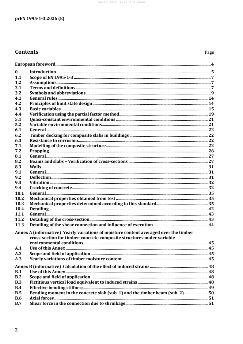
Contents Page
European foreword . 4
0 Introduction . 5
1.1 Scope of EN 1995-1-3 . 7
1.2 Assumptions . 7
3.1 Terms and definitions . 7
3.2 Symbols and abbreviations . 9
4.1 General rules . 14
4.2 Principles of limit state design . 14
4.3 Basic variables . 15
4.4 Verification using the partial factor method . 19
5.1 Quasi-constant environmental conditions . 21
5.2 Variable environmental conditions. 21
6.1 General . 22
6.2 Timber decking for composite slabs in buildings . 22
6.3 Resistance to corrosion . 22
7.1 Modelling of the composite structure . 22
7.2 Propping . 26
8.1 General . 27
8.2 Beams and slabs – Verification of cross-sections . 27
8.3 Walls . 31
9.1 General . 31
9.2 Deflection . 31
9.3 Vibration . 32
9.4 Cracking of concrete . 32
10.1 General . 35
10.2 Mechanical properties obtained from test . 35
10.3 Mechanical properties determined according to this standard. 35
10.4 Detailing . 42
11.1 General . 43
11.2 Detailing of the cross-section. 43
11.3 Detailing of the shear connection and influence of execution . 44
Annex A (informative) Yearly variations of moisture content averaged over the timber
cross-section for timber-concrete composite structures under variable
environmental conditions . 45
A.1 Use of this Annex . 45
A.2 Scope and field of application . 45
A.3 Yearly variations of timber moisture content . 45
Annex B (informative) Calculation of the effect of induced strains . 48
B.1 Use of this Annex . 48
B.2 Scope and field of application . 48
B.3 Fictitious vertical load equivalent to induced strains . 48
B.4 Effective bending stiffness . 49
B.5 Bending moment in the concrete slab (sub. 1) and the timber beam (sub. 2) . 50
B.6 Axial forces . 51
B.7 Shear force in the connection due to shrinkage . 51
Annex C (informative) Experimental determination of the resistance and stiffness of
timber to concrete connections . 53
C.1 Use of this Annex . 53
C.2 Scope and field of application . 53
C.3 Specimen configuration . 53
C.4 Testing protocol . 54
C.5 Determination of mechanical properties . 55
Annex D (informative) Load cases for checking timber-concrete-composite structures
including vertical loads and induced strains. 56
D.1 Use of this annex . 56
D.2 Scope and field of application . 56
D.3 General . 56
D.4 Load combination sets . 57
D.5 Calculating induced strains . 58
D.6 Calculating vertical loading . 59
D.7 Determining the effects of actions at different times . 60
Annex M (normative) Material and product properties for the design . 62
M.1 Use of this Annex . 62
M.2 Scope and field of application . 62
M.3 Timber Products . 62
M.4 Properties of the concrete . 63
M.5 Properties of the reinforcement . 63
M.6 Connectors for the connection between timber and concrete . 64
M.7 Pan head screws for the transfer of the uplifting forces in 10.3.4 . 64
Bibliography . 65
European foreword
This document (prEN 1995-1-3:2026) has been prepared by Technical Committee CEN/TC 250
“Structural Eurocodes”, the secretariat of which is held by BSI. CEN/TC 250 is responsible for all
Structural Eurocodes and has been assigned responsibility for structural and geotechnical design matters
by CEN.
This document is currently submitted to the CEN Enquiry.
This document will supersede CEN/TS 19103:2021.
The first generation of EN Eurocodes was published between 2002 and 2007. This document forms part
of the second generation of the Eurocodes, which have been prepared under Mandate M/515 issued to
CEN by the European Commission and the European Free Trade Association.
The Eurocodes have been drafted to be used in conjunction with relevant execution, material, product
and test standards, and to identify requirements for execution, materials, products and testing that are
relied upon by the Eurocodes.
The Eurocodes recognise the responsibility of each Member State and have safeguarded their right to
determine values related to regulatory safety matters at national level through the use of National
Annexes.
0 Introduction
0.1 Introduction to the Eurocodes
The Structural Eurocodes comprise the following standards generally consisting of a number of parts:
• EN 1990 Eurocode — Basis of structural and geotechnical design
• EN 1991 Eurocode 1 — Actions on structures
• EN 1992 Eurocode 2 — Design of concrete structures
• EN 1993 Eurocode 3 — Design of steel structures
• EN 1994 Eurocode 4 — Design of composite steel and concrete structures
• EN 1995 Eurocode 5 — Design of timber structures
• EN 1996 Eurocode 6 — Design of masonry structures
• EN 1997 Eurocode 7 — Geotechnical design
• EN 1998 Eurocode 8 — Design of structures for earthquake resistance
• EN 1999 Eurocode 9 — Design of aluminium structures
• EN 19100 Eurocode 10 — Design of glass structures
• New parts are under development, e.g. Eurocode for design of fibre-polymer composite structures
and design of tensioned membrane structures.
The Eurocodes are intended for use by designers, clients, manufacturers, constructors, relevant
authorities (in exercising their duties in accordance with national or international regulations),
educators, software developers, and committees drafting standards for related product, testing and
execution standards.
NOTE Some aspects of design are most appropriately specified by relevant authorities or, where not specified,
can be agreed on a project-specific basis between relevant parties such as designers and clients. The Eurocodes
identify such aspects making explicit reference to relevant authorities and relevant parties.
0.2 Introduction to EN 1995 (all parts)
EN 1995 (all parts) applies to the design of timber structures and gives specific design rules for buildings
and civil engineering timber works.
EN 1995 is subdivided in various parts:
EN 1995-1 in itself does not exist as a single document but comprises the following three separate
documents, the basic part being EN 1995-1-1:
EN 1995-1-1, Eurocode 5 — Design of timber structures — Part 1-1: General rules and rules for buildings
EN 1995-1-2, Eurocode 5 — Design of timber structures — Part 1-2: Structural fire design
EN 1995-1-3, Eurocode 5 — Design of timber structures — Part 1-3: Timber-concrete composite
structures
EN 1995-2, Eurocode 5 — Design of timber structures — Part 2: Bridges
EN 1995-3, Eurocode 5 — Design of timber structures — Part 3: Execution
EN 1995-2 “Bridges” refers to the common rules in EN 1995-1-1. The Clauses in EN 1995-2 supplement,
modify or supersede them, where relevant.
EN 1995-3 “Execution” refers to the common rules in EN 1995-1-1. The Clauses in EN 1995-3 supplement
the Clauses in EN 1995-1 and 1995-2.
0.3 Introduction to EN 1995-1-3
EN 1995-1-3 gives general design rules for timber-concrete composite structures.
0.4 Verbal forms used in the Eurocodes
The verb “shall” expresses a requirement strictly to be followed and from which no deviation is permitted
in order to comply with the Eurocodes.
The verb “should” expresses a highly recommended choice or course of action. Subject to national
regulation and/or any relevant contractual provisions, alternative approaches may be used/adopted
where technically justified.
The verb “may” expresses a course of action permissible within the limits of the Eurocodes.
The verb “can” expresses possibility and capability; it is used for statements of fact and clarification of
concepts.
0.5 National annex for EN 1995-1-3
National choice is allowed in this document where explicitly stated within notes. National choice includes
the selection of values for Nationally Determined Parameters (NDPs).
The national standard implementing EN 1995-1-3 can have a National Annex containing all national
choices to be used for the design of buildings and civil engineering works to be constructed in the relevant
country.
When no national choice is given, the default choice given in this document is to be used.
When no national choice is made and no default is given in this document, the choice can be specified by
a relevant authority or, where not specified, agreed for a specific project by appropriate parties.
National choice is allowed in EN 1995-1-3 through notes to the following clauses:
4.4.1.1(1) 4.4.1.2(2) – 2 choices 4.4.2(5)
National choice is allowed in EN 1995-1-3 on the application of the following informative annexes:
Annex A Annex B Annex C Annex D
The National Annex can contain, directly or by reference, non-contradictory complementary information
for ease of implementation, provided it does not alter any provisions of the Eurocodes.
1 Scope
1.1 Scope of EN 1995-1-3
(1) EN 1995-1-3 gives general design rules for timber-concrete composite structures.
(2) EN 1995-1-3 provides provisions for materials, design parameters, connections, detailing and
execution for timber-concrete composite structures. Recommendations for environmental parameters
(temperature and moisture content), design methods and test methods are given in the annexes.
(3) EN 1995-1-3 includes rules common to many types of timber-concrete composite but does not include
details for the design of glued timber-concrete composites, nor for bridges.
NOTE For the design of glued timber-concrete composites or bridges alternative references are available.
(4) EN 1995-1-3 covers the design of timber-concrete composite structures in both quasi-constant and
variable environmental conditions. For ease of use, it provides simple design rules for quasi-constant
environmental conditions and more complex rules for variable environmental conditions.
1.2 Assumptions
(1) The assumptions of EN 1990 (all parts) apply to this document. It is assumed that the requirements
for execution given in EN 1995-3 are complied with.
(2) EN 1995-1-3 is intended to be used in conjunction with EN 1990 (all parts), EN 1991 (all parts),
EN 1992 (all parts), EN 1994 (all parts), EN 1995 (all parts), EN 1998 (all parts) when timber structures
are built in seismic regions, and ENs for construction products relevant to timber structures.
2 Normative references
The following documents are referred to in the text in such a way that some or all of their content
constitutes requirements of this document. For dated references, only the edition cited applies. For
undated references, the latest edition of the referenced document (including any amendments) applies.
NOTE See the Bibliography for a list of other documents cited that are not normative references, including
those referenced as recommendations (i.e. in ‘should’ clauses), permissions (‘may’ clauses), possibilities (‘can’
clauses), and in notes.
EN 1990-1:2023+A1:2026, Eurocode — Basis of structural and geotechnical design — Part 1: New
structures
EN 1991 (all parts), Eurocode 1 — Actions on structures
EN 1992-1-1:2023, Eurocode 2 — Design of concrete structures — Part 1-1: General rules and rules for
buildings, bridges and civil engineering structures
EN 1993-1-8, Eurocode 3 — Design of steel structures — Part 1-8: Joints
EN 1995-1-1:2025, Eurocode 5 — Design of timber structures — Part 1-1: General rules and rules for
buildings
EN 14592, Timber structures — Dowel-type fasteners — Requirements
3 Terms, definitions and symbols
3.1 Terms and definitions
For the purposes of this document, the terms and definitions given in EN 1990-1, EN 1995-1-1 and the
following apply.
3.1.1
continuous fastener
fastener that is continuous along the length of the timber component
3.1.2
connection
any device or system formed of connected parts and an associated fastener or fasteners as well as, where
applicable, notches, which resists slip and transfers the related shear force at the interface between
timber and concrete
Note 1 to entry: Examples include dowel-type fasteners of any material, notches, plates and continuous fasteners,
any of which can be either mechanically fixed or bonded.
Note 2 to entry: Staples fall beyond the scope of this document.
3.1.3
induced strain
strain which is caused not by stresses but by volumetric changes, e.g. shrinkage, swelling or thermal
expansion
3.1.4
moisture content
percentage of mass of moisture in wood compared to its dry mass
3.1.5
quasi-constant environmental conditions
environmental conditions where
— timber is installed close to its expected moisture content in use ω and
use
— for softwood timber, the variation of average moisture content in use (Δω, see Formula (4.7)) does
not exceed 6 % and
— the temperature variations of the air do not exceed 20 °C
Note 1 to entry: The indoor conditions of a heated building are a typical example of quasi-constant conditions.
3.1.6
shrinkage of concrete
decrease in dimension of a piece of concrete due to the hardening process
3.1.7
shrinkage of timber
decrease in dimension of a piece of timber due to reduction of moisture content
3.1.8
swelling of timber
increase in dimension of a piece of timber due to increase of moisture content
3.1.9
thermal expansion
linear thermal expansion between given temperatures
3.1.10
variable environmental conditions
conditions that do not comply with quasi-constant environmental conditions
Note 1 to entry: Typical examples where variable environmental conditions can be experienced are balconies,
unheated roof spaces and outdoor covered and uncovered spaces.
3.2 Symbols and abbreviations
For the purposes of this document, the symbols given in EN 1995-1-1 and the following apply.
3.2.1 Latin upper-case letters
A Area of cross-section 1 or 2
1/2
A Effective area of the concrete cross-section
conc,ef
A Area of transverse reinforcement in concrete flange
sf
A Area of the timber cross-section
tim
C Coefficient which considers the interaction between vertical load q and induced strains
J,ind d
in terms of slip in the joint
C Coefficient which correlates the induced strains with a fictitious load
p,ind
E Modulus of elasticity of cross-section 1 or 2
1/2
F Maximum or minimum vertical load due to all vertical loads in the permanent load-
acc,perm
duration class, with vertical loads considered as accompanying.
E Modulus of elasticity of concrete
conc
E Effective long-term modulus of elasticity of concrete
conc,fin
E Characteristic combination of actions
k
F Maximum or minimum vertical load due to all vertical loads in the permanent load-
lead,perm
duration class, with vertical loads considered as leading;
E Quasi-permanent combination of actions
q,per
E Fundamental combination of actions
u
E Design value of the modulus of elasticity of the steel reinforcement as given in
s
EN 1992-1-1:2023, 5.2.4
E Mean modulus of elasticity of timber parallel to the grain
tim
E Effective long-term modulus of elasticity of timber parallel to the grain
tim,fin
(EI) Bending stiffness of the cross-section i
i
(EI) Effective bending stiffness according to EN 1995-1-1:2025, B.5
ef,EC5-AnnexB
(EI) Modified effective bending stiffness according to EN 1995-1-1:2025, B.5, which accounts
ef,ind
for the interaction between vertical load and induced strains
F Estimated load-carrying capacity as defined in accordance with EN 26891 and used in
est
determining the mean slip modulus for ultimate limit states
F Characteristic load-carrying capacity in an Annex C test, as determined in accordance
max
with EN 26891
F Design load-carrying resistance for a notched connection
Rd
F Design tensile force between the timber and the concrete cross-section
t,Ed
F Design shear force per connection
v,Ed
F Design load-carrying resistance per connection
v,Rd
F Characteristic connection shear strength
v,Rk
I Moment of inertia of cross-section 1 or 2
1/2
I Moment of inertia of the timber cross-section
tim
K Stiffness of the connection
K Maximum or minimum stiffness of the connection
max/min
K Reference stiffness of connection
ref
K Slip modulus for serviceability limit states
SLS
K Final slip modulus for serviceability limit states
SLS,fin
𝐾𝐾 Mean slip modulus for serviceability at time t
c
SLS,𝑡𝑡
c
K Instantaneous slip modulus of the connection for ultimate limit states
ULS
K Final slip modulus for ultimate limit states
ULS,fin
𝐾𝐾 Slip modulus for ultimate limit states at time t
c
ULS,𝑡𝑡
c
L Span of the beam
+ 0,8p ) Resulting bending moment due to external loads and part (80 %) of the fictitious load
M(qd ind
equivalent to induced strains
M(q ) Resulting bending moment due to external load only
d
M Bending moment of component i
i
M Maximum bending moment in cross-section 2
max,2
M Bending moment in the timber cross-section
tim
N Axial force in cross-section i
i
N Maximum axial force in cross-section 2
max,2
N Axial force in the timber cross-section
tim
T Initial average temperature in the concrete or timber at time t
0,conc/tim c
Maximum or minimum temperature in the concrete or timber (averaged over the cross-
Tmax/min,conc/tim
section)
V Effective maximum shear force
max
V(q ) Resulting shear force due to external load
d
X Design value of a strength property of timber or a wood-based product
d
3.2.2 Latin lower-case letters
a Spacing of fasteners parallel to the grain
𝑎𝑎 Distance from the centroid of cross-section 1 to the centroid of the effective composite
mm,1
cross-section
a Distance between the fastener and the unloaded or loaded edge
3c/3t
a Spacing of fasteners perpendicular to the grain
b Width of the concrete
conc
b Effective width of the concrete
conc,ef
b Notch width
n
b Width of the timber
tim
c Minimum concrete cover for durability of steel reinforcement
min,dur
c Nominal concrete cover
nom
d Fastener diameter or rebar diameter
d Diameter of the aggregate
g
e Distance between the centres of gravity of the cross-sections
f Design value of the compressive strength of concrete
cd
f Characteristic compressive cylinder strength of the concrete at 28 days
ck
f Design value of the tensile strength of concrete
ctd
f Characteristic embedment strength of the concrete member for evaluation of the load-
h,2,k
carrying resistance based on the Johansen models
f Effective design shear strength for the concrete
vcd
Design shear strength of the timber member
fv,t,d
f Design value of the yield strength of steel reinforcement
yd
h Height of the concrete without the depth of the notch
c
h Nominal height of the connector
s,c
h Thickness of the concrete flange
f
h Notch depth
n
k Deformation factor of timber
def
k ′ Deformation factor for connections between concrete and timber
def
k Modification factor for duration of load and moisture content for timber strength
mod
k ′ Modification factor for duration of load and moisture content for the strength of
mod
connections between concrete and timber
k Mean slip modulus for serviceability limit states, determined from Annex C tests in
s
accordance with EN 26891
k Coefficient for concrete, taking into account the effect of high sustained loads on
tc
compressive strength
k Adjustment factor for shear strength
v
l Minimal shear length of the timber
min
l Notch length
n
l Distance between notches
s
lshear Length of the shear surface around the shear connectors
l Length of timber in front of the notch
v
p Fictitious vertical load which represents the effects of induced strains on the structure
ind
q Design value of the external loads
d
s Effective spacing of the connections
ef
s Spacing of the transverse reinforcement bars in the concrete slab when checking in-
f
plane actions in the concrete
s Maximum or minimum spacing of the connections
max/min
s Transverse spacing of the fasteners when checking in-plane shear in the concrete
t
t A point in time
t The time when the concrete achieves the design strength or the time when the design-
imposed load is applied to the composite structure, whichever is the earlier
t Time for design for long-term condition
∞
t Time according to EN 13670:2009, 8.5(6) when curing and protection of the concrete
c
are complete
t Time of removal of props
p
t Age of concrete at the beginning of drying according to EN 1992-1-1:2023, B.6(1)
s
u Mean ultimate slip
ULS,tc
Ultimate slip determined in an Annex C test in accordance with EN 12512
vu
w Crack width in concrete
k
w Recommended maximum crack width in concrete EN 1992-1-1:2023, Table 9.1
max
z Distance between the centres of gravity of the cross-sections.
3.2.3 Greek upper-case letters
ΔF Design longitudinal shear over a certain length of beam in verification of concrete for in-
d
plane shear (including diaphragm actions)
Δω Total change over the annual cycle of the average timber moisture content due to
environmental conditions
−/+
Reduction or increase in average moisture content in timber over the annual cycle with
Δ𝜔𝜔
respect to the expected moisture content in use ω
use
Δω Timber moisture content variation (averaged over the timber cross-section) to be
calc
considered in the design
Δω Difference between the average timber moisture content in use ω and the average
d use
value ω at time t
0 c
ΔT Non-linear temperature difference component of the composite section
E
ΔT Temperature difference component about the z-z axis, with linear variation
MY
ΔT Temperature difference component about the y-y axis, with linear variation
MZ
−/+
Change in the average temperature of the concrete in the composite section from initial
Δ𝑇𝑇
u,conc
to minimum or maximum
ΔT Temperature variation of the cross-section i (1 or 2) to be considered in the design
u,i,calc
−/+
Change in the average temperature of the timber in the composite section from initial to
Δ𝑇𝑇
u,tim
minimum or maximum
Δε Difference in induced strain between the timber part and the concrete part
Δx Length under consideration in verification of concrete for in-plane shear (including
diaphragm actions)
θ Angle of the concrete strut
3.2.4 Greek lower-case letters
α Angle of a notch
α Coefficient of linear thermal expansion of concrete
c,T
α Coefficient of thermal expansion of the cross-section i
i,T
α Coefficient of linear moisture or thermal expansion of timber parallel to the grain
t,u/T
γ Composite factor of the concrete cross-section
γ Partial factor for concrete
c
γ Partial factor for shrinkage action
SH
γ Partial factor for thermal action
T
γ Partial factor for moisture content action
u
γ Partial factor for connection shear strength
v
ε Shrinkage of concrete according to EN 1992-1-1:2023
conc
ε Effective shrinkage of concrete
ef,conc
ε Induced strain of the cross-section
i
ρ Mean value of timber member density
mean
σ Design compressive or tensile stress in the concrete member, caused by axial force and
conc,c/t,d
bending
τ Design longitudinal shear stress for verification of concrete for in-plane shear
Ed
φ Creep coefficient of the concrete
ψ Factor for combination value of yearly variations of average timber moisture content
0,ω
ψ Factor for frequent value of yearly variations of average timber moisture content
1,ω
ψ Factor for quasi-permanent value of average timber moisture content variations
2,ω
ψ Coefficient for the effect of composite action on the creep coefficient of the concrete or
conc/tim
timber cross-section
ψ Coefficient for the effect of composite action on the creep coefficient of the connection
con
ω Moisture content of timber (averaged over the timber cross-section)
ω Moisture content of timber at time t
0 c
ω Maximum or minimum moisture content of timber during annual cycles
max/min
ω Expected moisture content of timber in use (mean over the year, averaged over the
use
timber cross-section)
4 Basis of design
4.1 General rules
(1) The design of timber-concrete composite structures shall be in accordance with the general rules
stated in EN 1990 (all parts) and the supplementary provisions for timber-concrete composite structures
stated in this document.
(2) The basic provisions of EN 1990-1:2023+A1:2026, Clause 4, are deemed to be satisfied for timber-
concrete composite structures when all the following are applied:
— Limit state design in conjunction with the partial factor method in accordance with EN 1990 (all
parts);
— Actions in accordance with EN 1991 (all parts);
— Action combinations in accordance with EN 1990 (all parts);
— Resistances, durability and serviceability in accordance with this standard, EN 1992-1-1,
EN 1994-1-1 and EN 1995-1-1.
4.2 Principles of limit state design
(1) In addition to the general principles stated in EN 1995-1-1:2025, 4.2 the effects of construction
sequence and changes of environmental conditions should be considered where relevant for the design.
NOTE Refer to 4.3.1.2 for the effect of changes of environmental conditions, where relevant.
(2) Due to the different creep behaviours of the concrete, the timber and the connection system, the final
long-term stress distribution in the composite structure at ultimate limit state, due to the fundamental
combination of actions E , should be calculated by superimposing:
u
— the stress distribution in the long-term due to the quasi-permanent combination of actions E
q,per
calculated using the effective moduli of elasticity of concrete E and timber E and the
conc,fin tim,fin
effective slip modulus of the connection K (refer to 4.3.2(8)); and
u,fin
— the instantaneous stress distribution due to the difference between the fundamental combination of
actions 𝐸𝐸 and the quasi-permanent combination of actions E , calculated using the moduli of
q,per
u
elasticity of concrete E and timber E and the slip modulus of the connection K .
conc tim u
(3) Due to the different creep behaviours of the concrete, the timber and the connection system, the final
deformation of the composite structure at serviceability limit state, due to the characteristic combination
of actions 𝐸𝐸 , should be calculated by superimposing:
k
— the total deformation in the long-term due to the quasi-permanent combination of actions E
q,per
calculated using the effective moduli of elasticity of concrete E and timber E and the
conc,fin tim,fin
effective slip modulus of the connection K (refer to 4.3.2(8)); and
SLS,fin
— the instantaneous deformation due to the difference between the characteristic combination of
actions E and the quasi-permanent combination of actions E , calculated using the moduli of
k q,per
elasticity of concrete E and timber E and the slip modulus of the connection K .
conc tim SLS
(4) As simplification the permanent and quasi-permanent actions resulting in creep deformations may
be determined by
𝐸𝐸 = ∑𝛾𝛾 ⋅ 𝐺𝐺 "+" ∑𝛾𝛾 ⋅ 𝜓𝜓 ⋅ 𝑄𝑄
(4.1)
d G,j k,j Q,i 2,i k,i
where
E is the design value of the permanent and quasi permanent action;
d
γ is the partial factor of a permanent action;
G,j
G is the permanent action;
k,j
"+" is the combination of the actions;
γ is the partial factor of a variable action;
Q,i
ψ is the combination factor according to EN 1990-1;
2,i
Q is the variable action.
k,i
(5) The short-term action without any effect on the creep deformation may be determined by
𝐸𝐸 = 𝛾𝛾 ⋅ 1 − 𝜓𝜓 ⋅ 𝑄𝑄 "+" ∑𝛾𝛾 ⋅ 𝜓𝜓 ⋅ 1 − 𝜓𝜓 ⋅ 𝑄𝑄
� � � � (4.2)
d Q,1 2,1 1,k Q,i 0,j 2,i j,k
where
E is the design value of the short-term action;
d
γ is the partial factor of a variable action;
Q,i
ψ2,i is the combination factor according to EN 1990-1;
Q is the variable action;
k,i
"+" is the combination of the actions;
ψ is the combination factor according to EN 1990-1.
0,j
(6) Both groups of actions should be superimposed.
4.3 Basic variables
4.3.1 Actions and environmental influences
4.3.1.1 General – Quasi-constant environmental conditions
(1) Actions to be used in design shall be obtained from the relevant parts of EN 1991.
(2) Duration of load and moisture content should be taken into account in the design for mechanical
resistance and serviceability in accordance with EN 1995-1-1 and this document.
NOTE Duration of load and moisture content affect the strength and stiffness properties of timber as well as
the strength and stiffness properties of the connection between timber and concrete.
(3) Shrinkage of concrete should be considered in design for verification of both the ultimate limit state
and the serviceability limit state.
NOTE The calculation of the effects of concrete shrinkage is given in Annex B. Concrete shrinkage is regarded as
an induced strain applied to the timber-concrete composite structure.
(4) For timber-concrete composite structures with a cast-in-situ concrete slab, the shrinkage of concrete
should be calculated from the time of concrete curing t , irrespective of whether the timber member is
c
propped or not.
(5) The increase in moisture content of the timber due to casting may be disregarded (see 11.1 (3)).
4.3.1.2 General – Variable environmental conditions
(1) In variable environmental conditions, the provisions given in 4.3.1.2 shall apply in addition to the
provisions in 4.3.1.1.
NOTE A guideline for the design in variable environmental conditions is given in Annex D.
(2) Due to the different linear expansion coefficients of timber and concrete, temperature differences
should be considered for verifications of both the ultimate limit state and the serviceability limit state.
NOTE In most cases, only the variations of the uniform temperature component in the concrete (ΔTu,conc) and
the timber (ΔTu,tim), as defined in Clause 4(3) of EN 1991-1-5:2025, can be considered.
(3) The effects of the linear and non-linear temperature difference components of the composite section
(ΔT , ΔT and ΔT ), as defined in EN 1991-1-5:2025, Clause 4(3) may be neglected.
MY MZ E
(4) The maximum and minimum temperature differences in the concrete and timber should be calculated
using Formulae (4.3) to (4.6):
+
Δ𝑇𝑇 = 𝑇𝑇 − 𝑇𝑇 (4.3)
u,conc max,conc 0,conc
+
Δ𝑇𝑇 = 𝑇𝑇 − 𝑇𝑇 (4.4)
u,tim max,tim 0,tim
and
−
Δ𝑇𝑇 = 𝑇𝑇 − 𝑇𝑇 (4.5)
u,conc min,conc 0,conc
−
Δ𝑇𝑇 = 𝑇𝑇 − 𝑇𝑇
(4.6)
u,tim min,tim 0,tim
where
+
is the change in the average temperature of the concrete in the composite section from
Δ𝑇𝑇
u,conc
initial to maximum;
T is the maximum value of the average temperature in the concrete (refer to
max,conc
EN 1991-1-5:2025, Clause 7);
T is the initial average temperature in the concrete at time t when the concrete has been
0,conc c
cured;
+
Δ𝑇𝑇 is the change in the average temperature of the timber in the composite section from
u,tim
initial to maximum;
ΔT is the maximum value of the average temperature in the timber (refer to
max,tim
EN 1991-1-5:2025, Clause 7);
T is the initial average temperature in the timber at time t when the concrete has been
0,tim c
cured;
NOTE If the initial temperatures when the structure is erected are unknown, reference can be made to
EN 1991-1-5.
−
Δ𝑇𝑇 is the change in the average temperature of the concrete in the composite section from
u,conc
initial to minimum;
T is the minimum value of the average temperature in the concrete (refer to
min,conc
EN 1991-1-5:2025, Clause 7);
−
Δ𝑇𝑇 is the change in the average temperature of the timber in the composite section from
u,tim
initial to minimum;
T is the minimum value of the average temperature in the timber (refer to
min,tim
EN 1991-1-5:2025, Clause 7).
(5) Shrinkage/swelling of timber in the longitudinal direction due to reductions/increases in moisture
content should be considered in design for verification of both the ultimate limit state and the
serviceability limit state.
(6) In general, shrinkage/swelling of the timber should be calculated by considering only the variation
over time of moisture content, averaged over the timber cross-section.
(7) When the timber is conditioned (see EN 1995-1-1:2025, 4.3.1.2(2)) to the expected moisture content
in use 𝜔𝜔 , the annual variation of the average timber moisture content due to the environmental
use
conditions Δ𝜔𝜔 (see Formula (4.7)) should consider the following:
+ −
— The increase (Δ𝜔𝜔 = Δ𝜔𝜔⁄2 > 0) and the decrease (Δ𝜔𝜔 = Δ𝜔𝜔⁄2 < 0) with respect to the expected
moisture content in use 𝑚𝑚𝑐𝑐 .
use
NOTE 1 Guidance for the evaluation of the variation Δ𝜔𝜔 is given in Annex A.
Δ𝜔𝜔 = 𝜔𝜔 − 𝜔𝜔 (4.7)
max min
where
ω is the maximum annual average timber moisture content;
max
ω is the minimum annual average timber moisture content.
min
— For structures in Europe, moisture content variations with a
...