


EN 13480-3:2017
(Main)Metallic industrial piping - Part 3: Design and calculation
General Information
- Abstract
This Part of this European Standard specifies the design and calculation of industrial metallic piping systems, including supports, covered by EN 13480.
- Status
- Withdrawn
- Publication Date
- 27-Jun-2017
- Withdrawal Date
- 22-Sep-2026
- Technical Committee
- CEN/TC 267 - Industrial piping and pipelines
- Drafting Committee
- CEN/TC 267/WG 8 - Maintenance of EN 13480 series
- Current Stage
- 9960 - Withdrawal effective - Withdrawal
- Start Date
- 24-Jul-2024
- Completion Date
- 23-Sep-2026
- Directive
- Harmonized Standard2014/68/EU - Directive 2014/68/EU of the European Parliament and of the Council of 15 May 2014 on the harmonisation of the laws of the Member States relating to the making available on the market of pressure equipmentOJ Ref: C, C 389 OJ Date: 17-Nov-2017

Relations
- Effective Date
- 08-Jun-2022
- Effective Date
- 05-Jul-2017
- Effective Date
- 18-Jan-2023
- Effective Date
- 17-Sep-2026
- Refers
EN 1993-6:2026 - Eurocode 3 - Design of steel structures - Part 6: Crane supporting structures - Effective Date
- 25-Mar-2026
- Effective Date
- 25-Mar-2026
- Effective Date
- 25-Mar-2026
- Effective Date
- 25-Mar-2026
- Refers
EN 1991-3:2026 - Eurocode 1 - Actions on structures - Part 3: Actions induced by cranes and machines - Effective Date
- 25-Mar-2026
- Effective Date
- 25-Mar-2026
- Effective Date
- 25-Mar-2026
- Effective Date
- 25-Mar-2026
- Effective Date
- 25-Mar-2026
- Effective Date
- 25-Mar-2026
- Effective Date
- 25-Mar-2026
Get Certified
Connect with accredited certification bodies for this standard

Institut za varilstvo d.o.o. (Welding Institute)
Slovenia's leading welding institute since 1952. ISO 3834, EN 1090, pressure equipment certification, NDT personnel, welder qualification. Only IIW Au
Sponsored listings
Frequently Asked Questions
EN 13480-3:2017 is a standard published by the European Committee for Standardization (CEN). Its full title is "Metallic industrial piping - Part 3: Design and calculation". This standard covers: This Part of this European Standard specifies the design and calculation of industrial metallic piping systems, including supports, covered by EN 13480.
This Part of this European Standard specifies the design and calculation of industrial metallic piping systems, including supports, covered by EN 13480.
EN 13480-3:2017 is classified under the following ICS (International Classification for Standards) categories: 23.040.01 - Pipeline components and pipelines in general. The ICS classification helps identify the subject area and facilitates finding related standards.
EN 13480-3:2017 has the following relationships with other standards: It is inter standard links to EN 13480-3:2012, EN 13480-3:2012/A1:2017, EN 13480-3:2024, EN 1993-7:2026, EN 1993-6:2026, EN 1991-1-6:2026, EN 1991-4:2026, EN 1993-4-2:2026, EN 1991-3:2026, EN 1993-1-11:2026, EN 1991-1-8:2026, EN 1993-3:2026, EN 1991-1-4:2026, EN 1993-4-1:2026, EN 1993-2:2026. Understanding these relationships helps ensure you are using the most current and applicable version of the standard.
EN 13480-3:2017 is associated with the following European legislation: EU Directives/Regulations: 2014/68/EU; Standardization Mandates: M/071. When a standard is cited in the Official Journal of the European Union, products manufactured in conformity with it benefit from a presumption of conformity with the essential requirements of the corresponding EU directive or regulation.
EN 13480-3:2017 is available in PDF format for immediate download after purchase. The document can be added to your cart and obtained through the secure checkout process. Digital delivery ensures instant access to the complete standard document.
Standards Content (Sample)
2003-01.Slovenski inštitut za standardizacijo. Razmnoževanje celote ali delov tega standarda ni dovoljeno.Metallische industrielle Rohrleitungen - Teil 3: Konstruktion und BerechnungTuyauteries industrielles métalliques - Partie 3: Conception et calculMetallic industrial piping - Part 3: Design and calculation77.140.75Jeklene cevi in cevni profili za posebne nameneSteel pipes and tubes for specific use23.040.10Železne in jeklene ceviIron and steel pipesICS:Ta slovenski standard je istoveten z:EN 13480-3:2017SIST EN 13480-3:2018en,fr,de01-januar-2018SIST EN 13480-3:2018SLOVENSKI
STANDARDSIST EN 13480-3:2012/A1:2018SIST EN 13480-3:20121DGRPHãþD
EUROPEAN STANDARD NORME EUROPÉENNE EUROPÄISCHE NORM
EN 13480-3
June
t r s y ICS
t uä r v rä r s Supersedes EN
s u v z ræ uã t r s tEnglish Version
Metallic industrial piping æ Part
uã Design and calculationTuyauteries industrielles métalliques æ Partie
u ã Conception et calcul
Industrielle metallische Rohrleitungen æ Teil
uã Konstruktion und Berechnung This European Standard was approved by CEN on
t s June
t r s yä
egulations which stipulate the conditions for giving this European Standard the status of a national standard without any alterationä Upætoædate lists and bibliographical references concerning such national standards may be obtained on application to the CENæCENELEC Management Centre or to any CEN memberä
translation under the responsibility of a CEN member into its own language and notified to the CENæCENELEC Management Centre has the same status as the official versionsä
CEN members are the national standards bodies of Austriaá Belgiumá Bulgariaá Croatiaá Cyprusá Czech Republicá Denmarká Estoniaá Finlandá Former Yugoslav Republic of Macedoniaá Franceá Germanyá Greeceá Hungaryá Icelandá Irelandá Italyá Latviaá Lithuaniaá Luxembourgá Maltaá Netherlandsá Norwayá Polandá Portugalá Romaniaá Serbiaá Slovakiaá Sloveniaá Spainá Swedená Switzerlandá Turkey and United Kingdomä
EUROPEAN COMMITTEE FOR STANDARDIZATION COMITÉ EUROPÉEN DE NORMALISATION EUROPÄISCHES KOMITEE FÜR NORMUNG
CEN-CENELEC Management Centre:
Avenue Marnix 17,
B-1000 Brussels
t r s y CEN All rights of exploitation in any form and by any means reserved worldwide for CEN national Membersä Refä Noä EN
s u v z ræ uã t r s y ESIST EN 13480-3:2018
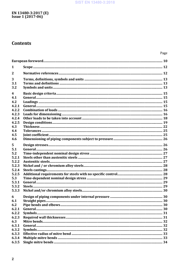
EN13480æ3:2017(E)Issue1(2017æ06)2ContentsFPageFEuropeanforeword.10 1Scope.12 2Normativereferences.12 3Terms,definitions,symbolsandunits.13 3.1Termsanddefinitions.13 3.2Symbolsandunits.13 4Basicdesigncriteria.15 4.1General.15 4.2Loadings.15 4.2.1General.15 4.2.2Combinationofloads.16 4.2.3Loadsfordimensioning.16 4.2.4Otherloadstobetakenintoaccount.18 4.2.5Designconditions.19 4.3Thickness.22 4.4Tolerances.25 4.5Jointcoefficient.25 4.6Dimensioningofpipingcomponentssubjecttopressure.26 5Designstresses.26 5.1General.26 5.2Timeæindependentnominaldesignstress.27 5.2.1Steelsotherthanausteniticsteels.27 5.2.2Austeniticsteels.27 5.2.3Nickeland/orchromiumalloysteels.28 5.2.4Steelscastings.28 5.2.5Additionalrequirementsforsteelswithnospecificcontrol.28 5.3Timeædependentnominaldesignstress.29 5.3.1General.29 5.3.2Steels.29 5.3.3Nickeland/orchromiumalloysteels.30 6Designofpipingcomponentsunderinternalpressure.30 6.1Straightpipes.30 6.2Pipebendsandelbows.30 6.2.1General.30 6.2.2Symbols.31 6.2.3Requiredwallthicknesses.31 6.3Mitrebends.32 6.3.1General.32 6.3.2Symbols.32 6.3.3Effectiveradiusofmitrebend.33 6.3.4Multiplemitrebends.33 6.3.5Singlemitrebends.34 SIST EN 13480-3:2018
EN13480æ3:2017(E)Issue1(2017æ06)36.3.6Adjacentstraightpipesectionsofmitrebends.34 6.4Reducers.34 6.4.1Conditionsofapplicability.34 6.4.2Specificdefinitions.35 6.4.3Specificsymbolsandabbreviations.35 6.4.4Conicalshells.36 6.4.5Junctionsægeneral.37 6.4.6Junctionbetweenthelargeendofaconeandacylinderwithoutaknuckle.37 6.4.7Junctionbetweenthelargeendofaconeandacylinderwithaknuckle.40 6.4.8Junctionbetweenthesmallendofaconeandacylinder.41 6.4.9Offsetreducers.43 6.4.10Specialforgedreducers.43 6.5Flexiblepipingcomponents.44 6.5.1General.44 6.5.2Expansionjoints.44 6.5.3Corrugatedmetalhoseassemblies.46 6.6Boltedflangeconnections.47 6.6.1General.47 6.6.2Symbols.47 6.6.3Standardflange.47 6.6.4Nonæstandardflange.48 7Designofendsunderinternalpressure.48 7.1Dishedends.48 7.1.1Symbols.48 7.1.2Hemisphericalends.49 7.1.3Torisphericalends.50 7.1.4Ellipsoidalends.51 7.1.5Calculationof.52 7.2Circularflatends.56 7.2.1General.56 7.2.2Symbols.56 7.2.3Unstayedflatcircularendsweldedtocylindricalshells/pipes.58 7.2.4Unstayedflatcircularboltedends.65 7.2.5Reinforcementsofopeningsinunstayedflatends.71 8Openingsandbranchconnections.74 8.1General.74 8.2Symbols.74 8.3Limitations.75 8.3.1Thicknessratio.75 8.3.2Openingsinthevicinityofdiscontinuities.77 8.3.3Typesofreinforcement.79 8.3.4Calculationmethod.80 8.3.5Ellipticalopeningsandobliquebranchconnections.80 8.3.6Reinforcingpads.82 8.3.7Dissimilarmaterialofshellandreinforcements.82 8.3.8Extrudedoutlets.82 8.3.9Forgedtee.82 8.3.10Branchesinbendsorelbows.83 8.3.11Screwedæinbranches.83 8.4Isolatedopenings.84 8.4.1General.84 8.4.2Unreinforcedopenings.87 SIST EN 13480-3:2018
EN13480æ3:2017(E)Issue1(2017æ06)48.4.3Reinforcedopeningswithdi/Di<0,8.87 8.4.4Reinforcedsingleopeningswith0,8
EN13480æ3:2017(E)Issue1(2017æ06)511.7.1Hollowcircularattachments.141 11.7.2Rectangularattachments.141 11.8Alternativecalculationmethods.141 12Flexibilityanalysisandacceptancecriteria.141 12.1Basicconditions.141 12.1.1General.141 12.1.2Loadingconditions.142 12.1.3Allowablestresses.142 12.2Pipingflexibility.144 12.2.1General.144 12.2.2Basicconditions.144 12.2.3Displacementstrains.144 12.2.4Displacementstresses.145 12.2.5Stressrange.146 12.2.6Coldpull.146 12.2.7Propertiesforflexibilityanalysis.147 12.2.8Supportingconditions.147 12.2.9Expansionjoints.149 12.2.10Flexibilityanalysis.149 12.3Flexibilityanalysis.151 12.3.1General.151 12.3.2Stressduetosustainedloads.152 12.3.3Stressduetosustainedandoccasionalorexceptionalloads.152 12.3.4Stressrangeduetothermalexpansionandalternatingloads.153 12.3.5Additionalconditionsforthecreeprange.154 12.3.6Stressesduetoasinglenonærepeatedsupportmovement.154 12.3.7Determinationofresultantmoments.155 12.3.8Alternativemethodforstresscalculation.157 12.3.9Reactions.157 12.4Fatigueanalysis.157 12.5Vibration.157 13PipeSupports.158 13.1Generalrequirements.158 13.1.1General.158 13.1.2Classificationofsupports.158 13.1.3Additionaldefinitions.159 13.1.4Boundaries.161 13.1.5Pipesupportsweldedtothepipe.163 13.2Selectionofpipesupports.164 13.2.1General.164 13.2.2Detaildesignofpipesupports.165 13.2.3Supportlocation.166 13.3Constanthangers/basemounted(pedestal)constantsupports.166 13.3.1General.166 13.3.2Loaddeviationfromcalibratedload.166 13.3.3Siteadjustmentofthecalibratedload.166 13.3.4Travelreserve(Overtravel).166 13.3.5Blocking.167 13.3.6IdentificationMarking/Nameplate.167 13.4Variableloadspringhangersandbasemounted(pedestal)variableloadspringsupports.167 13.4.1General.167 SIST EN 13480-3:2018
EN13480æ3:2017(E)Issue1(2017æ06)613.4.2Toleranceonspringrate.168 13.4.3Travelreserve(Overtravel).168 13.4.4Blocking.168 13.4.5Nameplate.168 13.5Rigidstruts.169 13.6Shockarrestors(shockabsorber,snubber).169 13.7Slidingsupports.170 13.8Anchors.170 13.9Documentationofsupports.170 13.10Markingofsupports.170 13.11Manufacturingofpipesupports.170 13.11.1Materialrequirements.170 13.11.2Designtemperaturesforsupportcomponents.171 13.11.3Designdetails.172 13.11.4Determinationofcomponentsizes.173 13.11.5Weldedconnections.174 13.11.6Threadedconnections.176 13.11.7Additionalrequirementsonsprings.177 13.11.8Designdetailsforrigidstruts.177 13.11.9Designdetailsforshockarrestors(shockabsorbers,snubbers).178 13.11.10Designdetailsforshockarrestors(shockabsorbers,snubbers).179 AnnexADynamicanalysis.180 A.1General.180 A.2Analysisbycalculation.180 A.2.1Seismicevents.180 A.2.2Rapidvalveclosure.184 A.2.3Flowinducedvibration.187 A.2.4Safetyvalvedischarge.189 A.2.5Allowablestresses.192 A.3Alternativemeansofdesignverification.192 A.3.1Comparativestudies.192 A.3.2Fullscaletesting.192 A.3.3Reducedscaletesting.192 AnnexBMoreaccuratecalculationofbendsandelbows.193 B.1General.193 B.2Symbolsandunits.193 B.3Requiredwallthickness.194 B.4Calculation.195 B.4.1Calculationofwallthickness.195 B.4.2Stresscalculation.197 AnnexCExpansionjoints.201 C.1Incorporationofexpansionjointsintopipingsystems.201 C.1.1General.201 C.1.2Typesofexpansionjoints.202 C.1.3Designofexpansionjoints.202 C.1.4Designingwithexpansionjoints.203 C.1.5Analysesandcalculation.205 C.1.6Coldpull.206 C.2Maximumspacingforunrestrainedaxiallycompensatedstraightruns.206 C.2.1General.206 C.2.2Calculationrules.206 SIST EN 13480-3:2018
EN13480æ3:2017(E)Issue1(2017æ06)7C.2.3Maximumspacingfordefinedconditions.207 C.3Indicationforthedesignofexpansionjoints.209 C.3.1General.209 C.3.2Informationforthesystemanalyst.209 AnnexDFlanges.210 D.1Purpose.210 D.2Specifictermsanddefinitions.210 D.3Specificsymbolsandabbreviations.211 D.4General.212 D.4.1Introduction.212 D.4.2Useofstandardflangeswithoutcalculation.212 D.4.3Bolting.213 D.4.4Flangeconstruction.215 D.4.5Machining.215 D.4.6Gaskets.215 D.5Narrowfacegasketedflanges.216 D.5.1General.216 D.5.2Boltloadsandareas.219 D.5.3Flangemoments.220 D.5.4Flangestressesandstresslimits.220 D.5.5Narrowfaceflangessubjecttoexternalpressure.226 D.5.6Lapjoints.226 D.5.7Splitringflanges.229 D.6Fullfaceflangeswithsoftringtypegaskets.230 D.6.1Specificsymbolsandabbreviations.231 D.6.2Boltloadsandareas.231 D.6.3Flangedesign.232 D.6.4Fullfaceflangessubjecttoexternalpressure.233 D.7Sealweldedflanges.233 D.8Reversenarrowfaceflanges.234 D.8.1Internalpressure.234 D.8.2Externalpressure.
...