

prEN 1489
(Main)Building valves - Pressure safety valves - Tests and requirements
- Abstract
This document specifies dimensions, materials and performance requirements, including methods of test, for pressure safety valves, of nominal sizes from DN 15 to DN 40, having working pressures from 0,1 MPa (1 bar) to 1,0 MPa (10 bar).
Pressure safety valves are intended for fitting to the potable water supply of storage water heaters, having a maximum storage temperature of 95 °C.
Pressure safety valves limit the pressure in hot water heaters.
Pressure safety valves do not control the temperature and alone do not constitute the protection required for storage water heaters. They are not intended to act as expansion valves under normal conditions.
NOTE The use of the device specified in this document does not override the need to use controls (e.g. thermostats and cut-outs) which act directly on the power sources of water heaters (for more information see Annex A).
- Status
- Not Published
- Publication Date
- 19-Jul-2027
- Technical Committee
- CEN/TC 164 - Water supply
- Current Stage
- 4020 - Submission to enquiry - Enquiry
- Start Date
- 10-Sep-2026
- Due Date
- 07-Apr-2026
- Completion Date
- 10-Sep-2026

prEN 1489 is a CEN draft European Standard for building valves, specifically pressure safety valves for storage water heaters. It specifies dimensions, materials, performance requirements and test methods for valves in nominal sizes DN 15 to DN 40 and working pressures from 0.1 MPa to 1.0 MPa. The valves are intended for potable water supplies to storage water heaters up to 95 °C, and they limit pressure rather than control temperature.
What does prEN 1489 specify?
prEN 1489 specifies the requirements for pressure safety valves used on storage water heaters. It covers what the valve must be made of, how it is designed, how it is tested, how it is marked, and what information must be delivered with it.
The document is organized into clauses on scope, normative references, terms and definitions, materials, disinfection compatibility, design and dimensions, tolerances and measuring accuracy, mechanical tests, hydraulic and endurance tests, acoustic testing, classification, designation, marking, and technical documents.
| Annex | What it covers |
|---|---|
| Annex A | Test sequences for the different samples and tests |
| Annex B | Classification of water heaters according to heating method and related safety-device selection |
| Annex C | Disinfection of the test rig |
In practice, this layout tells a manufacturer or tester where to find the product requirements, the test methods, and the installation-related information that supports selection and use.
What are the key requirements of prEN 1489?
Materials, finishes and chemical resistance
prEN 1489 requires materials and coatings that do not contaminate potable water and are suitable for the temperatures used in the tests. Materials with lower corrosion resistance need additional protection, and the material choice must be stated in technical documentation.
The document also covers three durability checks in Clause 4: detection of residual stress, corrosion resistance, and coating adherence. For products made from dezincification-resistant materials in countries where that is required, the material must meet the EN ISO 6509 series and be marked accordingly. In practice, this means the valve body and coating must survive real service and cleaning conditions without cracking, corroding or releasing harmful effects into the water.
Compatibility with disinfection
Clause 5 requires the valve to remain functional after shock disinfection. The test uses one of three disinfectant solutions - sodium hypochlorite, hydrogen peroxide or chlorine dioxide - under controlled concentration, temperature, pH and contact time.
This matters because valves may be exposed to curative disinfection in drinking-water installations. After the test, the device must still meet the cold-water pressure test requirements, so the manufacturer must show that disinfection does not impair opening or sealing performance.
Design, dimensions and operability
Clause 6 requires the valve to avoid seizure or sticking, keep sliding or rotating parts out of contact with water, and prevent the user from accessing setting components without damage. The body needs at least two flats for a spanner, and the valve needs a technical means for regular functional checking.
End connections must match the nominal size rules in the clause and relevant connection standards. Heat-based joints are not permitted. Where the valve has a replaceable cartridge, replacing it must not reduce leak-tightness. The operating control must work with a lift handle or rotary handle and must not stay locked open when manual effort is removed.
In practice, these requirements support safe installation, routine checking and maintenance without special workarounds.
Test conditions and measurement control
Clause 7 sets the tolerances used in testing and the accuracy expected from measuring instruments. It also states the default test medium, which is water at ambient temperature unless the document gives something else.
This is important because the pass/fail results depend on controlled pressure, temperature, time and force. Test labs need the right instrument accuracy to make the results comparable.
Mechanical and hydraulic performance
Clause 8 checks the body and operating parts for mechanical strength. The body is subjected to pressure, bending and torsional loading, and the operating control is also mechanically loaded.
Clause 9 checks hydraulic behavior. The document links the nominal set pressure (Pnr) to the water-tightness pressure, rating pressure, initial opening pressure, opening pressure and closing pressure. Separate tests are defined for cold water and saturated steam. The cold-water test verifies opening, tightness, discharge flow and resealing, while the steam test checks opening, leakage and sustained flow at pressure.
Clause 9 also includes endurance testing with 10,000 cycles at elevated water temperature, operating-control tests, a check for air break to drain where present, and a thermal-shock test for plastic components. No acoustic testing is required.
For a buyer or engineer, this section is the core proof that the valve will open when needed, reseal correctly, and still work after repeated use.
Classification, marking and delivery information
Clause 11 classifies the valves by DN for water-heater application, with a table linking size to maximum electrical power output for direct heating systems. Annex B helps place this in the wider context of water-heater safety-device selection by heating method.
Clause 12 gives the designation format, and Clause 13 lists the permanent markings, including manufacturer identification, DN size, nominal set pressure, flow direction, operating position, date or code of manufacture, model reference and, where relevant, the high inlet-temperature marking. Clause 14 requires installation and use instructions in the language of the country of distribution, including connection, corrosion precautions, dripping during heating, maintenance and applicable rules.
What terms does prEN 1489 define?
- Pressure safety valve - a valve that limits water pressure in the heater by discharging water to drain and, in a temperature-control failure, discharging stored energy as water or steam.
- Additional outlet connection - an outlet that allows cold potable water to supply an additional device, such as an inline tempering valve.
- Drain device or drain function - a feature that lets the water heater be drained without removing the pressure safety valve, and that also serves as the discharge path for water or steam.
- Air break to drain - a vertical separation by air inlet or full disconnection between the outlet and the spill-over level of the atmospheric drain.
- Nominal set pressure (Pnr) - the pressure set during production; this is often simply called the set pressure.
- Water tightness pressure (Pe) - the pressure up to which the valve remains closed.
- Initial opening pressure (Pdc) - the pressure at which the valve opens for the first time.
- Closing pressure (Pf) - the pressure at which the valve closes after reaching the rating pressure.
Who uses prEN 1489?
prEN 1489 is used by valve manufacturers, water-heater manufacturers, test laboratories, certification bodies, and quality managers. It is also relevant to buyers and specifiers who need pressure safety valves for potable-water storage heaters and want to compare products on the same basis.
Installers and maintenance teams use the delivery instructions and marking requirements to fit the valve correctly, check the flow direction, operate the control, and plan periodic inspection. Annex B is useful when selecting safety devices for different heater heating methods.
What changed in prEN 1489 from the previous edition?
prEN 1489 supersedes EN 1489:2000. The foreword states these significant technical changes:
- the chapter on materials was completely revised;
- testing with disinfectant was introduced;
- the coating test procedure was revised;
- normative references were updated;
- editorial changes were made throughout the document.
Which standards are used with prEN 1489?
prEN 1489 refers to these standards for related requirements and test methods:
- EN 806-5 - operation and maintenance guidance for water installations.
- EN 1254-2 - compression fittings for copper tubes.
- EN 1488 - expansion groups, also referenced in Annex B for indirect heated systems.
- EN 1717 - protection against pollution by backflow and the dimensions for drain-related connections.
- EN 10226-1 - pipe threads with pressure-tight joints on the threads.
- EN ISO 6509 - dezincification resistance testing for copper alloys.
- EN ISO 9227 - salt-spray corrosion testing.
- ISO 691 - wrench and socket openings for torque testing.
- EN ISO 228-1 - thread dimensions and tolerances for pressure-tight joints not made on the threads, named in the design clause.
- ISO 6957 - ammonia test basis used for the residual-stress test.
What does the prEN 1489 document contain?
The document contains dimensional requirements, material rules, surface-finish requirements, and detailed test methods for stress corrosion, corrosion resistance, coating adherence, disinfection compatibility, mechanical strength, hydraulic performance, endurance, operating control, and thermal shock. It also includes pressure and flow tables for cold-water and steam tests, plus a classification table for valve size versus heater power.
Annex A gives the test sequence planning, Annex B gives heater classification by heating method, and Annex C shows an example test rig for disinfection. For a laboratory or certification body, these parts are the practical roadmap for setting up samples, running the tests in the right order, and recording the results.
Relations
- Effective Date
- 18-Dec-2024
Get Certified
Connect with accredited certification bodies for this standard

DIBt (Deutsches Institut für Bautechnik)
German Institute for Building Technology.

DIN CERTCO
DIN Group product certification.

Aboma Certification B.V.
Specialized in construction, metal, and transport sectors.
Sponsored listings
Frequently Asked Questions
prEN 1489 is a draft published by the European Committee for Standardization (CEN). Its full title is "Building valves - Pressure safety valves - Tests and requirements". This standard covers: This document specifies dimensions, materials and performance requirements, including methods of test, for pressure safety valves, of nominal sizes from DN 15 to DN 40, having working pressures from 0,1 MPa (1 bar) to 1,0 MPa (10 bar). Pressure safety valves are intended for fitting to the potable water supply of storage water heaters, having a maximum storage temperature of 95 °C. Pressure safety valves limit the pressure in hot water heaters. Pressure safety valves do not control the temperature and alone do not constitute the protection required for storage water heaters. They are not intended to act as expansion valves under normal conditions. NOTE The use of the device specified in this document does not override the need to use controls (e.g. thermostats and cut-outs) which act directly on the power sources of water heaters (for more information see Annex A).
This document specifies dimensions, materials and performance requirements, including methods of test, for pressure safety valves, of nominal sizes from DN 15 to DN 40, having working pressures from 0,1 MPa (1 bar) to 1,0 MPa (10 bar). Pressure safety valves are intended for fitting to the potable water supply of storage water heaters, having a maximum storage temperature of 95 °C. Pressure safety valves limit the pressure in hot water heaters. Pressure safety valves do not control the temperature and alone do not constitute the protection required for storage water heaters. They are not intended to act as expansion valves under normal conditions. NOTE The use of the device specified in this document does not override the need to use controls (e.g. thermostats and cut-outs) which act directly on the power sources of water heaters (for more information see Annex A).
prEN 1489 is classified under the following ICS (International Classification for Standards) categories: 91.140.60 - Water supply systems. The ICS classification helps identify the subject area and facilitates finding related standards.
prEN 1489 has the following relationships with other standards: It is inter standard links to EN 1489:2000. Understanding these relationships helps ensure you are using the most current and applicable version of the standard.
prEN 1489 is associated with the following European legislation: EU Directives/Regulations: 305/2011. When a standard is cited in the Official Journal of the European Union, products manufactured in conformity with it benefit from a presumption of conformity with the essential requirements of the corresponding EU directive or regulation.
prEN 1489 is available in PDF format for immediate download after purchase. The document can be added to your cart and obtained through the secure checkout process. Digital delivery ensures instant access to the complete standard document.
Standards Content (Sample)
SLOVENSKI STANDARD
01-november-2026
Ventili v stavbah - Varnostni tlačni ventili - Preskusi in zahteve
Building valves - Pressure safety valves - Tests and requirements
Gebäudearmaturen - Sicherheitsventile - Prüfungen und Anforderungen
Robinetterie de bâtiment - Soupapes de sécurité - Essais et exigences
Ta slovenski standard je istoveten z: prEN 1489
ICS:
23.060.01 Ventili na splošno Valves in general
91.140.60 Sistemi za oskrbo z vodo Water supply systems
2003-01.Slovenski inštitut za standardizacijo. Razmnoževanje celote ali delov tega standarda ni dovoljeno.
DRAFT
EUROPEAN STANDARD
NORME EUROPÉENNE
EUROPÄISCHE NORM
September 2026
ICS 91.140.60 Will supersede EN 1489:2000
English Version
Building valves - Pressure safety valves - Tests and
requirements
Robinetterie de bâtiment - Soupapes de sécurité - Gebäudearmaturen - Sicherheitsventile - Prüfungen
Essais et prescriptions und Anforderungen
This draft European Standard is submitted to CEN members for enquiry. It has been drawn up by the Technical Committee
CEN/TC 164.
If this draft becomes a European Standard, CEN members are bound to comply with the CEN/CENELEC Internal Regulations
which stipulate the conditions for giving this European Standard the status of a national standard without any alteration.
This draft European Standard was established by CEN in three official versions (English, French, German). A version in any other
language made by translation under the responsibility of a CEN member into its own language and notified to the CEN-CENELEC
Management Centre has the same status as the official versions.
CEN members are the national standards bodies of Austria, Belgium, Bulgaria, Croatia, Cyprus, Czech Republic, Denmark, Estonia,
Finland, France, Germany, Greece, Hungary, Iceland, Ireland, Italy, Latvia, Lithuania, Luxembourg, Malta, Netherlands, Norway,
Poland, Portugal, Republic of North Macedonia, Romania, Serbia, Slovakia, Slovenia, Spain, Sweden, Switzerland, Türkiye and
United Kingdom.
Recipients of this draft are invited to submit, with their comments, notification of any relevant patent rights of which they are
aware and to provide supporting documentation.
Warning : This document is not a European Standard. It is distributed for review and comments. It is subject to change without
notice and shall not be referred to as a European Standard.
EUROPEAN COMMITTEE FOR STANDARDIZATION
COMITÉ EUROPÉEN DE NORMALISATION
EUROPÄISCHES KOMITEE FÜR NORMUNG
CEN-CENELEC Management Centre: Rue de la Science 23, B-1040 Brussels
© 2026 CEN All rights of exploitation in any form and by any means reserved Ref. No. prEN 1489:2026 E
worldwide for CEN national Members.
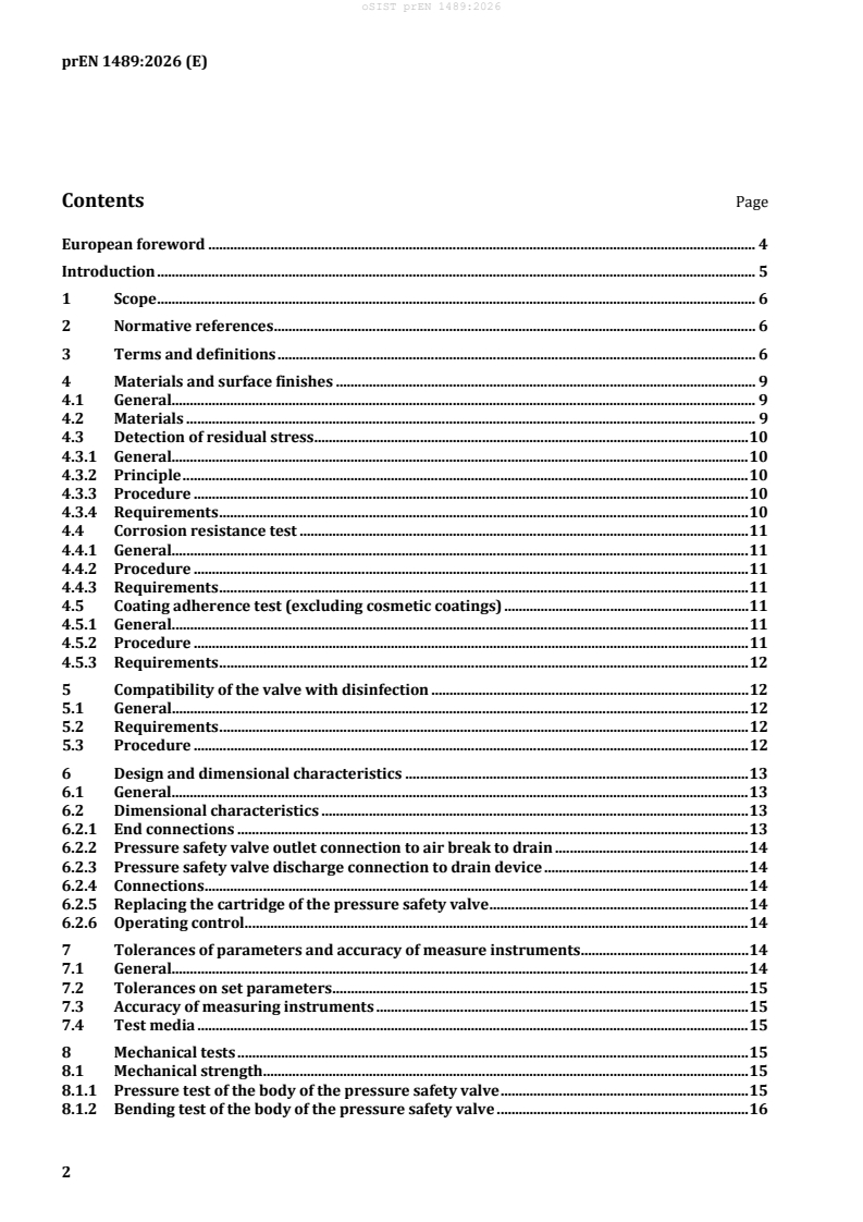
Contents Page
European foreword . 4
Introduction . 5
1 Scope . 6
2 Normative references . 6
3 Terms and definitions . 6
4 Materials and surface finishes . 9
4.1 General. 9
4.2 Materials . 9
4.3 Detection of residual stress . 10
4.3.1 General. 10
4.3.2 Principle . 10
4.3.3 Procedure . 10
4.3.4 Requirements . 10
4.4 Corrosion resistance test . 11
4.4.1 General. 11
4.4.2 Procedure . 11
4.4.3 Requirements . 11
4.5 Coating adherence test (excluding cosmetic coatings) . 11
4.5.1 General. 11
4.5.2 Procedure . 11
4.5.3 Requirements . 12
5 Compatibility of the valve with disinfection . 12
5.1 General. 12
5.2 Requirements . 12
5.3 Procedure . 12
6 Design and dimensional characteristics . 13
6.1 General. 13
6.2 Dimensional characteristics . 13
6.2.1 End connections . 13
6.2.2 Pressure safety valve outlet connection to air break to drain . 14
6.2.3 Pressure safety valve discharge connection to drain device . 14
6.2.4 Connections . 14
6.2.5 Replacing the cartridge of the pressure safety valve . 14
6.2.6 Operating control . 14
7 Tolerances of parameters and accuracy of measure instruments . 14
7.1 General. 14
7.2 Tolerances on set parameters . 15
7.3 Accuracy of measuring instruments . 15
7.4 Test media . 15
8 Mechanical tests . 15
8.1 Mechanical strength . 15
8.1.1 Pressure test of the body of the pressure safety valve . 15
8.1.2 Bending test of the body of the pressure safety valve . 16
8.1.3 Torsional strength test of the pressure safety valve’s body . 16
8.1.4 Mechanical strength test of the operating control of the pressure safety valve . 17
9 Pressure safety valve . 17
9.1 Hydraulic tests . 17
9.1.1 Pressures . 17
9.1.2 Cold water pressure test . 18
9.1.3 Steam test . 19
9.2 Endurance test . 20
9.2.1 Procedure . 20
9.2.2 Requirements . 20
9.3 Operating control tests . 21
9.3.1 Operation test . 21
9.3.2 Endurance test . 21
9.4 Air break to drain . 21
9.5 Resistance to thermal shocks test for plastic components. 21
9.5.1 Procedure . 21
9.5.2 Requirements . 21
10 Acoustic tests . 22
11 Classification . 22
12 Designation . 23
13 Marking . 23
14 Technical documents and presentation at delivery . 24
Annex A (informative) Test sequences . 25
Annex B (informative) Classification of water heaters according to heating method . 27
Annex C (informative) Disinfection of test rig . 29
Bibliography . 30
European foreword
This document (prEN 1489:2026) has been prepared by Technical Committee CEN/TC 164 “Water
supply”, the secretariat of which is held by AFNOR.
This document is currently submitted to the CEN Enquiry.
This document will supersede EN 1489:2000.
— chapter on materials was completely revised;
— testing with disinfectant was introduced;
— coating test procedure was revised;
— normative references were updated;
— editorial changes have been made throughout the entire document.
Introduction
With regard to potential adverse effect on the quality of water intended for human consumption, caused
by the product covered by this document:
a) This document provides no information as to whether the product may be used without restriction
in any of the Member States of the EU or EFTA.
b) It should be noted that, whilst awaiting the adoption of verifiable European criteria, existing national
regulations concerning the use and or the characteristics of this product remain in force.
1 Scope
This document specifies dimensions, materials and performance requirements, including methods of test,
for pressure safety valves, of nominal sizes from DN 15 to DN 40, having working pressures from
0,1 MPa (1 bar) to 1,0 MPa (10 bar).
Pressure safety valves are intended for fitting to the potable water supply of storage water heaters,
having a maximum storage temperature of 95 °C.
Pressure safety valves limit the pressure in hot water heaters.
Pressure safety valves do not control the temperature and alone do not constitute the protection required
for storage water heaters. They are not intended to act as expansion valves under normal conditions.
NOTE The use of the device specified in this document does not override the need to use controls (e.g.
thermostats and cut-outs) which act directly on the power sources of water heaters (for more information see
Annex A).
2 Normative references
The following documents are referred to in the text in such a way that some or all of their content
constitutes requirements of this document. For dated references, only the edition cited applies. For
undated references, the latest edition of the referenced document (including any amendments) applies.
EN 806-5, Specifications for installations inside buildings conveying water for human consumption —
Part 5: Operation and maintenance
EN 1254-2, Copper and copper alloys — Plumbing fittings — Part 2: Compression fittings for use with
copper tubes
EN 1488, Building valves — Expansion groups — Tests and requirements
EN 1717, Protection against pollution of water intended for human consumption in potable water
installations and general requirements for devices to prevent pollution by backflow
EN 10226-1, Pipe threads where pressure tight joints are made on the threads — Part 1: Taper external
threads and parallel internal threads — Dimensions, tolerances and designation
EN ISO 6509 (all parts), Corrosion of metals and alloys — Determination of dezincification resistance of
copper alloys with zinc (ISO 6509)
EN ISO 9227, Corrosion tests in artificial atmospheres — Salt spray tests (ISO 9227)
ISO 691, Assembly tools for screws and nuts — Wrench and socket openings — Tolerances for general use
3 Terms and definitions
For the purposes of this document, the following terms and definitions apply.
ISO and IEC maintain terminology databases for use in standardization at the following addresses:
— ISO Online browsing platform: available at https://www.iso.org/obp/
— IEC Electropedia: available at https://www.electropedia.org/
All pressures are gauge unless otherwise stated.
3.1
additional outlet connection
outlet connection that allows cold potable water to be supplied to an additional device
Note 1 to entry: For example, inline hot water supply tempering valves etc.
3.2
pressure safety valve
valve that limits the pressure of the water in the water heater to a predetermined value by discharging
water to the drain and in case of temperature control failure, discharging the energy stored as water or
steam
Note 1 to entry: For the purpose of this standard the pressure safety valve is hereafter referred as the “device”.
3.3
drain device or drain function
device that allows the water heater to be drained without removing the pressure safety valve and the
outlet connection which is also used to discharge water or steam from the pressure safety valve
3.4
air break to drain
vertical distance realised by air inlets or full disconnection between the lowest point of the outlet and the
spill-over level of the atmospheric drain overflow
3.5
nominal set pressure
P
nr
pressure of the pressure safety valve which is set on production
Note 1 to entry: The “nominal set pressure” (Pnr) is often called “set pressure”.
3.6
water tightness pressure
P
e
pressure up to which the pressure safety valve is closed
Note 1 to entry: See Figure 1.
3.7
initial opening pressure
Pdc
pressure at which the pressure safety valve opens for the first time
3.8
initial opening pressure
P
dc, water
pressure at which the pressure safety valve opens for the first time, as indicated by the first
droplet of water at the outlet of the pressure safety valve, after a period of storage
Note 1 to entry: See Figure 1.
3.9
initial opening pressure
P
dc, steam
pressure at which the pressure safety valve opens for the first time, as indicated by the first
appearance of steam at the outlet of the pressure safety valve, after a period of storage
Note 1 to entry: See Figure 1.
3.10
opening pressure
P
o
pressure at which the pressure safety valve opens
3.11
opening pressure
P
o, water
pressure at which the pressure safety valve opens, as indicated by the appearance of water at
the discharge connection of the pressure safety valve
Note 1 to entry: See Figure 1.
3.12
opening pressure
P
o, steam
pressure at which the pressure safety valve opens, as indicated by the appearance of steam at
the discharge connection of the pressure safety valve
3.13
rating pressure
P
dn
pressure at which the discharged flow is above the limit given in Table 6 and Table 7
Note 1 to entry: See Figure 1.
3.14
closing pressure
P
f
pressure at which the pressure safety valve closes after having reached the rating pressure
Note 1 to entry: See Figure 1.
Key
Y pressure
X time
Figure 1 — Pressures
4 Materials and surface finishes
4.1 General
NOTE The selection of materials is normally the responsibility of the manufacturer.
The materials shall satisfy the following requirements:
a) The materials and coatings shall not contaminate the potable water.
b) The nature of the materials and coatings used shall be stated in a technical document.
c) Materials with insufficient corrosion resistance (e.g. cast iron, aluminium) shall have additional
protection.
d) The materials used shall be suitable for the temperatures specified in the tests in this document.
e) The materials, and in particular copper alloys, for which recommendations or international
standards exist, shall comply with the relevant recommendations or international standards.
4.2 Materials
All materials coming into contact with water intended for human consumption shall present no health
risk nor cause any change to the water in terms of quality, appearance, smell or taste.
Copper-zinc alloys containing more than 15 % zinc are subject to dezincification when submitted to
water capable of dezincification. In the countries where the use of products made of dezincification
resistant materials is required, the materials used shall guarantee a dezincification depth less than
200 µm in any direction. For this purpose, materials shall be tested in accordance with the
EN ISO 6509 series and the product shall be marked in compliance with the indications according to
Clause 14.
4.3 Detection of residual stress
4.3.1 General
This test shall be performed for bodies made out of material potentially susceptible to stress corrosion
cracking and with female threads according to EN 10226-1 and compression ends according to
EN 1254-2.
4.3.2 Principle
This test is based on ISO 6957. Its purpose is to verify the resistance to cracking under stress corrosion
in ammonia medium (as described in 4.3.3, b)).
The test entails exposing test specimens consisting of the assembled device in an atmosphere loaded with
ammonia vapour.
4.3.3 Procedure
The paragraph below is integrated from ISO 6957.
Test solution:
a) Solutions of analysis quality and of distilled water shall be used.
b) Solution of ammonia at 20 % (in weight) shall be used.
c) The pH of the test solution shall be adjusted to 9,5 by using hydrochloric acid.
d) The test temperature shall be (23 ± 2) °C with a measurement uncertainty of ± 1 K.
Test specimen:
a) The test specimen consists of three samples of a single assembled product. The test specimen shall
be inserted into the test enclosure under no stress.
Instructions:
a) Rinse the test specimens with a clean non-chlorinated solvent (for example, ethanol).
b) Let it dry in the air.
c) Insert the test specimens into the test enclosure along with the ammonia solution. The volume of the
container made of glass (e.g. desiccator) shall be minimum (10 ± 1) l.
d) The volume of the solution inserted shall be (200 ± 10) ml per 3 l of total volume of the container
(e.g. for a 10 l container it means (667 ± 33) ml).
e) Place the test specimens in the container in such a way that they will not touch each other and that
they will not be in contact with the solution.
After an exposure of (24 ± 2) h, remove the test specimens and rinse them.
4.3.4 Requirements
After the test, the devices shall be inspected visually for stress corrosion cracking. No cracking shall occur
on any component. Test according to 9.1.2 (cold water pressure test) shall be fulfilled.
The results shall not deviate by more than 10 % from the original values.
4.4 Corrosion resistance test
4.4.1 General
The purpose of the corrosion resistance test is to qualify all used materials of the external part of the
product. The whole device shall be tested, not only the parts in contact with potable water. Positioning
restrictions given by the manufacturer shall be taken into account when placing the device into the tank.
4.4.2 Procedure
Samples shall be prepared for the corrosion resistance test as described as follows.
Carry out the test under the conditions described in EN ISO 9227, specifically for the neutral saline-spray
test, in the following way:
a) Subject the device with closed in- and outlet connection to spraying for at least 100 h, interrupt the
spraying treatment for (48 ± 1) h while maintaining the heat in the tank and resume the spraying
treatment for another (100 ± 1) h.
b) For the duration of the tests, the tank should only be opened to check and maintain the conditions,
the maximum rest period in spraying being 30 min per day. The heating should not be interrupted;
samples under test should not be handled, washed or checked.
After treatment and before visual examination, rinse the test samples in water to remove any salt residue.
4.4.3 Requirements
The device shall comply with the requirements as included in cold water pressure test (9.1.2). The results
shall not deviate by more than 10 % from the original values.
4.5 Coating adherence test (excluding cosmetic coatings)
4.5.1 General
The coating adherence test is only applicable for the valve housing and if the purpose of the coating is
corrosion protection as specified in 4.1 c).
4.5.2 Procedure
At three different locations on the coated surface cut, with a cutting tool with a tungsten carbide tip of the
type shown on Figure 2, crosses or V’s approximately 10 mm × 10 mm in length. The crosses or Vs shall
be cut by pulling the handle of the chisel parallel to the surface. The depth shall be such that they
completely cut through the electrolytic deposit, without forcing that coating into the base metal. Proceed
test according 4.4.2.
prEN 1
...