


EN 12732:2021
(Main)Gas infrastructure - Welding steel pipework - Functional requirements
General Information
- Abstract
This document contains requirements for the production and testing of weld joints for the installation and modification, including in-service welding, of onshore steel pipelines and pipework used in gas infrastructure. This includes all pressure ranges and processed, non-toxic and non-corrosive natural gas according to EN ISO 13686 and non-conventional gases such as (injected) biomethane and hydrogen, where:
- the pipeline elements are made of unalloyed or low-alloyed carbon steel;
- the pipeline is not located within commercial or industrial premises as integral part of the industrial process on those premises except for any pipelines and facilities delivering gas to such premises;
- the pipework is not located within households or industrial installations according to EN 1775 or EN 15001;
- the design temperature of the system is between −40 °C up to and including 120 °C.
For injected biomethane or hydrogen a detailed technical evaluation of the functional requirements is required, ensuring there are no other constituents or properties of the gases that can affect the integrity of the pipeline.
This document is not applicable to welds produced prior to the publication of this document.
This document specifies common basic principles for gas infrastructure. Users of this document are expected to be aware that there can exist more detailed national standards and/or codes of practice in the CEN member countries.
This document is intended to be applied in association with these national standards and/or codes of practice setting out the above-mentioned basic principles.
In the event of conflicts in terms of more restrictive requirements in national legislation/regulation with the requirements of this document, the national legislation/regulation takes precedence as illustrated in CEN/TR 13737 (all parts).
NOTE CEN/TR 13737 (all parts) contains:
- clarification of relevant legislation/regulations applicable in a country;
- if appropriate, more restrictive national requirements;
- national contact point for the latest information.
- Status
- Published
- Publication Date
- 16-Nov-2021
- Withdrawal Date
- 30-May-2022
- Technical Committee
- CEN/TC 234 - Gas infrastructure
- Drafting Committee
- CEN/TC 234/WG 3 - Gas Transportation
- Current Stage
- 6060 - Definitive text made available (DAV) - Publishing
- Start Date
- 17-Nov-2021
- Due Date
- 30-Oct-2021
- Completion Date
- 17-Nov-2021
Buy Documents


Overview
EN 12732:2021 (EN 12732:2021) defines functional requirements for welding steel pipework used in gas infrastructure. It covers production, inspection and testing of weld joints for installation, modification and in-service welding of onshore steel pipelines and pipework carrying processed, non-toxic and non‑corrosive natural gas (per EN ISO 13686), and non‑conventional gases such as injected biomethane and hydrogen (subject to detailed technical evaluation). The standard applies to pipelines made from unalloyed or low‑alloy carbon steel with design temperatures from −40 °C to 120 °C and to all pressure ranges, while excluding certain in‑building and household pipework per EN 1775 / EN 15001. It is intended to be used alongside national standards and codes of practice; national legislation takes precedence where more restrictive.
Key topics and technical requirements
- Scope & applicability: Onshore gas transmission and distribution pipelines (exclusions noted); not retroactive to welds produced before publication.
- Quality system requirements: Expectations for documented processes and traceability for welding operations.
- Welding contractors & procedures: Qualification and control of contractors, welding procedure specifications (WPS), preheat/post‑weld rules.
- Welder and operator qualifications: Criteria and additional requirements (see Annex A) for manual and mechanized welding personnel.
- Production welding: Joint types, preparation, tack welding, repair rules and destructive testing thresholds (e.g., DP over 16 bar).
- Attachment & in‑service welding: Hot‑tapping, cathodic protection connections and safety/supervision for live repairs (Annex D).
- Inspection & testing: Non‑destructive testing (NDT) methods, destructive testing (DT), acceptance levels (including AUT, UT, TOFD, RT) and documentation requirements (Annexes C, E, F, J).
- Specific acceptance criteria: Visual, radiographic and other NDT acceptance criteria (Annexes G, H, I).
- Ancillary guidance: Topics such as brazing, stud welding for cathodic protection and differences from previous editions (Annexes K, L).
Practical applications and users
This standard is essential for:
- Pipeline owners and operators (asset integrity, construction, maintenance)
- Welding contractors and fabrication shops (WPS, qualifications)
- Inspection and NDT providers (AUT, UT, TOFD, RT procedures)
- Design engineers, project managers and safety officers (hot‑tap and in‑service welding)
- Regulators and auditors ensuring compliance with gas infrastructure safety practices
Use EN 12732 to establish consistent welding controls, ensure qualified personnel, specify appropriate NDT/acceptance criteria, and document welded joint integrity for gas pipeline projects.
Related standards and notes
- Intended to be applied with relevant national standards/codes of practice; national legislation supersedes where more restrictive (see CEN/TR 13737).
- Referenced international standards include EN ISO 13686, EN 1775, EN 15001 and various EN/ISO welding and NDT standards cited in the normative references.
Relations
- Replaces
EN 12732:2013+A1:2014 - Gas infrastructure - Welding steel pipework - Functional requirements - Effective Date
- 08-Jun-2022
- Effective Date
- 27-May-2026
- Effective Date
- 28-Jan-2026
- Effective Date
- 28-Jan-2026
- Effective Date
- 28-Jan-2026
- Effective Date
- 28-Jan-2026
- Effective Date
- 28-Jan-2026
- Effective Date
- 28-Jan-2026
- Effective Date
- 28-Jan-2026
- Effective Date
- 28-Jan-2026
- Effective Date
- 28-Jan-2026
- Effective Date
- 28-Jan-2026
- Effective Date
- 28-Jan-2026
- Effective Date
- 28-Jan-2026
- Effective Date
- 28-Jan-2026
Buy Documents
Get Certified
Connect with accredited certification bodies for this standard

DVS-ZERT GmbH
German welding certification society.
CARES (UK Certification Authority for Reinforcing Steels)
UK certification for reinforcing steels and construction.
EWF/IIW (European/International Welding Federation)
International welding personnel certification.
Sponsored listings
Frequently Asked Questions
EN 12732:2021 is a standard published by the European Committee for Standardization (CEN). Its full title is "Gas infrastructure - Welding steel pipework - Functional requirements". This standard covers: This document contains requirements for the production and testing of weld joints for the installation and modification, including in-service welding, of onshore steel pipelines and pipework used in gas infrastructure. This includes all pressure ranges and processed, non-toxic and non-corrosive natural gas according to EN ISO 13686 and non-conventional gases such as (injected) biomethane and hydrogen, where: - the pipeline elements are made of unalloyed or low-alloyed carbon steel; - the pipeline is not located within commercial or industrial premises as integral part of the industrial process on those premises except for any pipelines and facilities delivering gas to such premises; - the pipework is not located within households or industrial installations according to EN 1775 or EN 15001; - the design temperature of the system is between −40 °C up to and including 120 °C. For injected biomethane or hydrogen a detailed technical evaluation of the functional requirements is required, ensuring there are no other constituents or properties of the gases that can affect the integrity of the pipeline. This document is not applicable to welds produced prior to the publication of this document. This document specifies common basic principles for gas infrastructure. Users of this document are expected to be aware that there can exist more detailed national standards and/or codes of practice in the CEN member countries. This document is intended to be applied in association with these national standards and/or codes of practice setting out the above-mentioned basic principles. In the event of conflicts in terms of more restrictive requirements in national legislation/regulation with the requirements of this document, the national legislation/regulation takes precedence as illustrated in CEN/TR 13737 (all parts). NOTE CEN/TR 13737 (all parts) contains: - clarification of relevant legislation/regulations applicable in a country; - if appropriate, more restrictive national requirements; - national contact point for the latest information.
This document contains requirements for the production and testing of weld joints for the installation and modification, including in-service welding, of onshore steel pipelines and pipework used in gas infrastructure. This includes all pressure ranges and processed, non-toxic and non-corrosive natural gas according to EN ISO 13686 and non-conventional gases such as (injected) biomethane and hydrogen, where: - the pipeline elements are made of unalloyed or low-alloyed carbon steel; - the pipeline is not located within commercial or industrial premises as integral part of the industrial process on those premises except for any pipelines and facilities delivering gas to such premises; - the pipework is not located within households or industrial installations according to EN 1775 or EN 15001; - the design temperature of the system is between −40 °C up to and including 120 °C. For injected biomethane or hydrogen a detailed technical evaluation of the functional requirements is required, ensuring there are no other constituents or properties of the gases that can affect the integrity of the pipeline. This document is not applicable to welds produced prior to the publication of this document. This document specifies common basic principles for gas infrastructure. Users of this document are expected to be aware that there can exist more detailed national standards and/or codes of practice in the CEN member countries. This document is intended to be applied in association with these national standards and/or codes of practice setting out the above-mentioned basic principles. In the event of conflicts in terms of more restrictive requirements in national legislation/regulation with the requirements of this document, the national legislation/regulation takes precedence as illustrated in CEN/TR 13737 (all parts). NOTE CEN/TR 13737 (all parts) contains: - clarification of relevant legislation/regulations applicable in a country; - if appropriate, more restrictive national requirements; - national contact point for the latest information.
EN 12732:2021 is classified under the following ICS (International Classification for Standards) categories: 25.160.40 - Welded joints and welds. The ICS classification helps identify the subject area and facilitates finding related standards.
EN 12732:2021 has the following relationships with other standards: It is inter standard links to EN 12732:2013+A1:2014, EN ISO 18275:2026, EN ISO 23279:2017, EN ISO 14732:2013, EN ISO 19285:2017, EN 10204:2004, EN ISO 11666:2018, EN ISO 20378:2018, EN ISO 6520-1:2007, EN ISO 10863:2011, EN ISO 5817:2023, EN ISO 9606-1:2017, EN ISO 14341:2020, EN ISO 17637:2016, EN ISO 9692-1:2013. Understanding these relationships helps ensure you are using the most current and applicable version of the standard.
EN 12732:2021 is associated with the following European legislation: Standardization Mandates: M/017. When a standard is cited in the Official Journal of the European Union, products manufactured in conformity with it benefit from a presumption of conformity with the essential requirements of the corresponding EU directive or regulation.
EN 12732:2021 is available in PDF format for immediate download after purchase. The document can be added to your cart and obtained through the secure checkout process. Digital delivery ensures instant access to the complete standard document.
Standards Content (Sample)
SLOVENSKI STANDARD
01-februar-2022
Nadomešča:
SIST EN 12732:2013+A1:2014
Infrastruktura za plin - Varjenje jeklenih cevovodov - Funkcionalne zahteve
Gas infrastructure - Welding steel pipework - Functional requirements
Gasinfrastruktur - Schweißen an Rohrleitungen aus Stahl - Funktionale Anforderungen
Infrastructures gazières - Soudage des tuyauteries en acier - Prescriptions fonctionnelles
Ta slovenski standard je istoveten z: EN 12732:2021
ICS:
25.160.40 Varjeni spoji in vari Welded joints and welds
91.140.40 Sistemi za oskrbo s plinom Gas supply systems
2003-01.Slovenski inštitut za standardizacijo. Razmnoževanje celote ali delov tega standarda ni dovoljeno.
EN 12732
EUROPEAN STANDARD
NORME EUROPÉENNE
November 2021
EUROPÄISCHE NORM
ICS 25.160.40 Supersedes EN 12732:2013+A1:2014
English Version
Gas infrastructure - Welding steel pipework - Functional
requirements
Infrastructures gazières - Soudage des tuyauteries en Gasinfrastruktur - Schweißen an Rohrleitungen aus
acier - Prescriptions fonctionnelles Stahl - Funktionale Anforderungen
This European Standard was approved by CEN on 3 October 2021.
CEN members are bound to comply with the CEN/CENELEC Internal Regulations which stipulate the conditions for giving this
European Standard the status of a national standard without any alteration. Up-to-date lists and bibliographical references
concerning such national standards may be obtained on application to the CEN-CENELEC Management Centre or to any CEN
member.
This European Standard exists in three official versions (English, French, German). A version in any other language made by
translation under the responsibility of a CEN member into its own language and notified to the CEN-CENELEC Management
Centre has the same status as the official versions.
CEN members are the national standards bodies of Austria, Belgium, Bulgaria, Croatia, Cyprus, Czech Republic, Denmark, Estonia,
Finland, France, Germany, Greece, Hungary, Iceland, Ireland, Italy, Latvia, Lithuania, Luxembourg, Malta, Netherlands, Norway,
Poland, Portugal, Republic of North Macedonia, Romania, Serbia, Slovakia, Slovenia, Spain, Sweden, Switzerland, Turkey and
United Kingdom.
EUROPEAN COMMITTEE FOR STANDARDIZATION
COMITÉ EUROPÉEN DE NORMALISATION
EUROPÄISCHES KOMITEE FÜR NORMUNG
CEN-CENELEC Management Centre: Rue de la Science 23, B-1040 Brussels
© 2021 CEN All rights of exploitation in any form and by any means reserved Ref. No. EN 12732:2021 E
worldwide for CEN national Members.
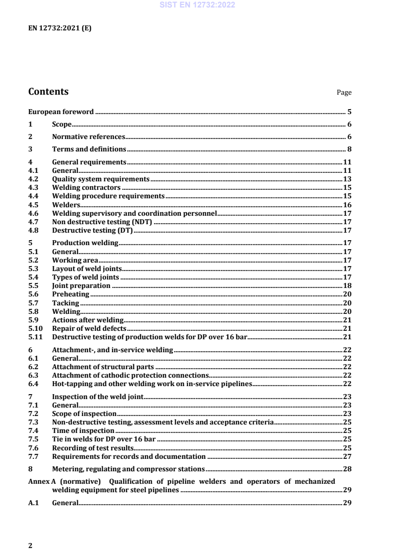
Contents Page
European foreword . 5
1 Scope . 6
2 Normative references . 6
3 Terms and definitions . 8
4 General requirements . 11
4.1 General. 11
4.2 Quality system requirements . 13
4.3 Welding contractors . 15
4.4 Welding procedure requirements . 15
4.5 Welders. 16
4.6 Welding supervisory and coordination personnel . 17
4.7 Non destructive testing (NDT) . 17
4.8 Destructive testing (DT) . 17
5 Production welding . 17
5.1 General. 17
5.2 Working area . 17
5.3 Layout of weld joints . 17
5.4 Types of weld joints . 17
5.5 Joint preparation . 18
5.6 Preheating . 20
5.7 Tacking . 20
5.8 Welding . 20
5.9 Actions after welding . 21
5.10 Repair of weld defects . 21
5.11 Destructive testing of production welds for DP over 16 bar . 21
6 Attachment-, and in-service welding . 22
6.1 General. 22
6.2 Attachment of structural parts . 22
6.3 Attachment of cathodic protection connections . 22
6.4 Hot-tapping and other welding work on in-service pipelines . 22
7 Inspection of the weld joint . 23
7.1 General. 23
7.2 Scope of inspection . 23
7.3 Non-destructive testing, assessment levels and acceptance criteria . 25
7.4 Time of inspection . 25
7.5 Tie in welds for DP over 16 bar . 25
7.6 Recording of test results. 25
7.7 Requirements for records and documentation . 27
8 Metering, regulating and compressor stations . 28
Annex A (normative) Qualification of pipeline welders and operators of mechanized
welding equipment for steel pipelines . 29
A.1 General. 29
A.2 Additional requirements to EN ISO 9606-1:2017 and EN ISO 14732:2013 . 29
A.3 Additional requirements for operators of mechanized welding equipment . 30
Annex B (informative) Testing on lamination defects . 31
Annex C (informative) Time-of-flight diffraction technique (TOFD) . 32
C.1 General . 32
C.2 Additional and substitutional requirements to EN ISO 10863:2011 . 32
Annex D (normative) Critical aspects for hot-tap welding or welding on in-service pipelines . 41
D.1 General . 41
D.2 procedural requirements . 41
D.3 Supervision . 42
D.4 Safety precautions . 42
D.5 Welding consumables . 42
D.6 Welding procedure specification (WPS) . 43
D.7 Welding procedure qualification for in-service welding . 43
D.8 Qualification of the welder . 43
D.9 Weld preparation long seam . 43
D.10 Weld preparation circular seam . 43
D.11 Repairs . 44
D.12 Non-destructive testing . 44
D.13 Pressure test . 44
D.14 Documentation . 44
Annex E (normative) AUT examination of joints . 45
E.1 Extent of this annex . 45
E.2 General Requirements . 45
E.3 Field Inspection . 52
E.4 Adjustments of the AUT system . 54
E.5 Acceptance criteria tier 1 . 54
E.6 Acceptance criteria tier 2 . 56
Annex F (informative) Manual ultrasonic testing of weld joints for wall thickness between
approximately 6 mm and 8 mm . 60
F.1 General . 60
F.2 Setting of range . 60
F.3 Sensitivity adjustment when using the Distance Gain Size method . 60
Annex G (normative) EPRG acceptance criteria . 64
G.1 General . 64
G.2 EPRG defect acceptance levels and defect limits . 64
G.3 Requirements . 65
Annex H (normative) Visual acceptance criteria according to EN ISO 5817:2014 . 71
Annex I (normative) RT acceptance criteria according to EN ISO 10675 and
EN ISO 5817:2014 . 73
Annex J (normative) Alternative method and acceptance criteria for UT inspection . 75
J.1 Distance Gain Size method . 75
J.2 Comparative Element method. 75
J.3 General. 75
Annex K (informative) Brazing and stud welding of connections for cathodic protection
systems . 77
K.1 Joining techniques . 77
K.2 Procedure qualification . 77
K.3 Operation qualification . 78
K.4 Production joints . 78
Annex L (informative) Significant technical changes between this European Standard and
the previous edition . 79
Bibliography . 80
European foreword
This document (EN 12732:2021) has been prepared by Technical Committee CEN/TC 234 “Gas
infrastructure”, the secretariat of which is held by DIN.
This European Standard shall be given the status of a national standard, either by publication of an
identical text or by endorsement, at the latest by May 2022, and conflicting national standards shall be
withdrawn at the latest by May 2022.
Attention is drawn to the possibility that some of the elements of this document may be the subject of
patent rights. CEN shall not be held responsible for identifying any or all such patent rights.
This document supersedes EN 12732:2013+A1:2014.
This document has been prepared under a Standardization Request given to CEN by the European
Commission and the European Free Trade Association.
Annex L provides details of significant technical changes between this document and the previous
edition.
There is a complete suite of functional standards prepared by CEN/TC 234 “Gas infrastructure” to cover
all parts from the input of gas to the transmission system up to the inlet connection of the gas
appliances, whether for domestic, commercial or industrial purposes.
In preparing this document, a basic understanding of gas infrastructure by the user has been assumed.
Gas infrastructure is complex and the importance on safety of its construction and use has led to the
development of very detailed codes of practice and operating manuals in the member countries. These
detailed statements embrace recognized standards of gas engineering and the specific requirements
imposed by the legal structures of the member countries.
CEN/TC 234 will continue its work updating this standard to the latest developments at regular
intervals.
Any feedback and questions on this document should be directed to the users’ national standards body.
A complete listing of these bodies can be found on the CEN website.
According to the CEN-CENELEC Internal Regulations, the national standards organisations of the
following countries are bound to implement this European Standard: Austria, Belgium, Bulgaria,
Croatia, Cyprus, Czech Republic, Denmark, Estonia, Finland, France, Germany, Greece, Hungary, Iceland,
Ireland, Italy, Latvia, Lithuania, Luxembourg, Malta, Netherlands, Norway, Poland, Portugal, Republic of
North Macedonia, Romania, Serbia, Slovakia, Slovenia, Spain, Sweden, Switzerland, Turkey and the
United Kingdom.
1 Scope
This document contains requirements for the production and testing of weld joints for the installation
and modification, including in-service welding, of onshore steel pipelines and pipework used in gas
infrastructure. This includes all pressure ranges and processed, non-toxic and non-corrosive natural gas
according to EN ISO 13686 and non-conventional gases such as (injected) biomethane and hydrogen,
where:
• the pipeline elements are made of unalloyed or low-alloyed carbon steel;
• the pipeline is not located within commercial or industrial premises as integral part of the industrial
process on those premises except for any pipelines and facilities delivering gas to such premises;
• the pipework is not located within households or industrial installations according to EN 1775 or
EN 15001;
• the design temperature of the system is between −40 °C up to and including 120 °C.
For injected biomethane or hydrogen a detailed technical evaluation of the functional requirements is
required, ensuring there are no other constituents or properties of the gases that can affect the integrity
of the pipeline.
This document is not applicable to welds produced prior to the publication of this document.
This document specifies common basic principles for gas infrastructure. Users of this document are
expected to be aware that there can exist more detailed national standards and/or codes of practice in
the CEN member countries.
This document is intended to be applied in association with these national standards and/or codes of
practice setting out the above-mentioned basic principles.
In the event of conflicts in terms of more restrictive requirements in national legislation/regulation
with the requirements of this document, the national legislation/regulation takes precedence as
illustrated in CEN/TR 13737 (all parts).
NOTE CEN/TR 13737 (all parts) contains:
• clarification of relevant legislation/regulations applicable in a country;
• if appropriate, more restrictive national requirements;
• national contact point for the latest information.
2 Normative references
The following documents are referred to in the text in such a way that some or all of their content
constitutes requirements of this document. For dated references, only the edition cited applies. For
undated references, the latest edition of the referenced document (including any amendments) applies.
EN 1708-1, Welding - Basic welded joint details in steel - Part 1: Pressurized components
EN 10204, Metallic products - Types of inspection documents
EN ISO 636, Welding consumables - Rods, wires and deposits for tungsten inert gas welding of non-alloy
and fine-grain steels - Classification (ISO 636)
EN ISO 2560, Welding consumables - Covered electrodes for manual metal arc welding of non-alloy and
fine grain steels - Classification (ISO 2560)
EN ISO 3834-2, Quality requirements for fusion welding of metallic materials - Part 2: Comprehensive
quality requirements (ISO 3834-2)
EN ISO 5817, Welding - Fusion-welded joints in steel, nickel, titanium and their alloys (beam welding
excluded) - Quality levels for imperfections (ISO 5817)
EN ISO 6520-1, Welding and allied processes - Classification of geometric imperfections in metallic
materials - Part 1: Fusion welding (ISO 6520-1)
EN ISO 9606-1:2017, Qualification testing of welders - Fusion welding - Part 1: Steels (ISO 9606-1:2017)
EN ISO 9692-1, Welding and allied processes - Types of joint preparation - Part 1: Manual metal arc
welding, gas-shielded metal arc welding, gas welding, TIG welding and beam welding of steels (ISO 9692-
1)
EN ISO 9712, Non-destructive testing - Qualification and certification of NDT personnel (ISO 9712)
EN ISO 10675-1:2016, Non-destructive testing of welds - Acceptance levels for radiographic testing - Part
1: Steel, nickel, titanium and their alloys (ISO 10675-1:2016)
EN ISO 10863:2011, Non-destructive testing of welds - Ultrasonic testing - Use of time-of-flight diffraction
technique (TOFD) (ISO 10863:2011)
EN ISO 10893-8, Non-destructive testing of steel tubes - Part 8: Automated ultrasonic testing of seamless
and welded steel tubes for the detection of laminar imperfections (ISO 10893-8)
EN ISO 11666, Non-destructive testing of welds - Ultrasonic testing - Acceptance levels (ISO 11666)
EN ISO 13588, Non-destructive testing of welds - Ultrasonic testing - Use of automated phased array
technology (ISO 13588)
EN ISO 14171, Welding consumables - Solid wire electrodes, tubular cored electrodes and electrode/flux
combinations for submerged arc welding of non alloy and fine grain steels - Classification (ISO 14171)
EN ISO 14174, Welding consumables - Fluxes for submerged arc welding and electroslag welding -
Classification (ISO 14174)
EN ISO 14175, Welding consumables - Gases and gas mixtures for fusion welding and allied processes (ISO
14175)
EN ISO 14341, Welding consumables - Wire electrodes and weld deposits for gas shielded metal arc
welding of non alloy and fine grain steels - Classification (ISO 14341)
EN ISO 14732:2013, Welding personnel - Qualification testing of welding operators and weld setters for
mechanized and automatic welding of metallic materials (ISO 14732:2013)
EN ISO 15609-1, Specification and qualification of welding procedures for metallic materials - Welding
procedure specification - Part 1: Arc welding (ISO 15609-1)
EN ISO 15614-1, Specification and qualification of welding procedures for metallic materials - Welding
procedure test - Part 1: Arc and gas welding of steels and arc welding of nickel and nickel alloys (ISO
15614-1)
EN ISO 17636-1, Non-destructive testing of welds - Radiographic testing - Part 1: X- and gamma-ray
techniques with film (ISO 17636-1)
EN ISO 17636-2, Non-destructive testing of welds - Radiographic testing - Part 2: X- and gamma-ray
techniques with digital detectors (ISO 17636-2)
EN ISO 17637, Non-destructive testing of welds - Visual testing of fusion-welded joints (ISO 17637)
EN ISO 17638, Non-destructive testing of welds - Magnetic particle testing (ISO 17638)
EN ISO 17640, Non-destructive testing of welds - Ultrasonic testing - Techniques, testing levels, and
assessment (ISO 17640)
EN ISO 18275, Welding consumables - Covered electrodes for manual metal arc welding of high-strength
steels - Classification (ISO 18275)
EN ISO 19285, Non-destructive testing of welds - Phased array ultrasonic testing (PAUT) - Acceptance
levels (ISO 19285)
EN ISO 20378, Welding consumables - Rods for gas welding of non-alloy and creep-resisting steels -
Classification (ISO 20378)
EN ISO 23279, Non-destructive testing of welds - Ultrasonic testing - Characterization of discontinuities in
welds (ISO 23279)
3 Terms and definitions
For the purposes of this document, the following terms and definitions apply.
ISO and IEC maintain terminological databases for use in standardization at the following addresses:
• ISO Online browsing platform: available at https://www.iso.org/obp
• IEC Electropedia: available at https://www.electropedia.org/
3.1
design pressure
DP
pressure on which design calculations are based
3.2
design temperature
DT
temperature on which the design calculations are based
3.3
round porosity
gas pore in a weld where the length is less as three times the width
3.4
elongated porosity
gas pore in a weld where the length is more than three times the width
3.5
gas
gaseous fuel which is in a gaseous state at a temperature of 15 °C under atmospheric pressure
(1,013 25 bar absolute)
3.6
gas infrastructure
all pipelines, stations and installations from the input of gas to the transmission system up to the inlet
connection of the gas appliances, whether for domestic, commercial or industrial purposes
3.7
gas compressor station
installation used for:
• transporting gas in pipelines;
• compressing gas from a pipeline to a gas storage facility or vice versa
Note 1 to entry: More than one of the above functions could be performed simultaneously or alternately.
3.8
gas distribution system
pipeline system including piping above and below ground and all other equipment necessary to deliver
the gas to the consumer
3.9
gas transmission
activity intended to convey gas from one place to another through pipelines in order to deliver gas to
distribution systems or to industrial consumers
3.10
hot pass
second pass for a cellulosic welded pipe girth weld
3.11
installation
equipment and facilities for the extraction, production, chemical treatment, measurement, control,
storage or off-take of the transported gas
3.12
national requirements
requirements following from applicable national legislation or national standards
3.13
onshore pipeline
buried and/or above ground pipeline including those sections laid in or across inland lakes or water
courses
3.14
pipeline
system of pipework with all associated equipment and stations up to the point of delivery
Note 1 to entry: This pipework is mainly below ground but also includes above ground parts.
3.15
pipeline components
elements from which a pipeline is constructed. The following are distinct pipeline elements: pipe
including cold-formed bends, fittings
Note 1 to entry: Reducers, tees, factory-made elbows and bends, flanges, caps, welding stubs, mechanical joints,
fabrications, manufactured from elements referred above.
Note 2 to entry: Manifolds, slug catchers, pig launching/receiving stations, metering and control runs, equipment.
Note 3 to entry: Valves, expansion joints, insulating joints, pressure regulators, pumps, compressors, dedicated
pressure vessels.
3.16
pipeline operator
private or public organisation authorised to design, construct, and/or operate and maintain the gas
infrastructure, i.e. gas transmission operators (TSO) and gas distribution operators (DSO)
3.17
pipework
assembly of pipes and fittings
3.18
pressure
gauge pressure of the fluid inside the system, measured in static conditions
3.19
root pass
first pass in a single sided pipe girth weld
3.20
station
plant or facility for the operation and/or processing of gas infrastructure
3.21
test pressure
TP
pressure to which a part of the gas infrastructure is subjected to, to ensure safe operation
Note 1 to entry: The test pressure can be different for the different parts of the infrastructure to be tested.
3.22
weld repair
process of repairing a defect that is discovered after the weld has been completed, by additional
welding
Note 1 to entry: The repair can involve complete removal of a cylinder of pipe or removal of a localized area by
grinding or other means followed by additional welding.
3.23
welder
person who holds and manipulates the electrode holder, welding torch or blow pipe by hand
3.24
weld operator
person who operates a mechanized welding system
3.25
welding procedure specification
WPS
document that has been qualified and provides the required variables of the welding procedure to
ensure repeatability during production welding
3.26
temper bead method
weld sequence where the heat-affected zone of the base material is softened as much as possible
3.27
hydrogen dissolved in metal, HDM
amount in ml of diffusible hydrogen in 100 mg of weld metal
4 General requirements
4.1 General
Table 1 assigns the application areas to quality requirement categories as a function of the design
pressure and pipe materials used.
When using this document the following shall be defined by the pipeline operator, the applicable
paragraph is given in brackets:
a) applicable quality requirement category. (scope);
b) applicable quality requirements as defined in Table 2 (4.2);
c) are there specific requirements on visual testing (VT) personnel, and/or qualification (4.2);
d) applicable welding qualification standards (4.2);
e) are all weld metal tensile tests required (4.4);
f) for category B and C, are batch certificates required for welding consumables, when required the
pipeline operator has to define the contents of the certificate (4.4.2);
g) for filler materials not in accordance with listed European standards, is batch qualification with
WPQR allowed (4.4.2);
h) if overmatching weld material is required (4.4.2);
i) if hot deformation for misalignment compensation is allowed for materials of R ≤ 360 MPa (6.2);
t 0,5
j) is the weld always to be covered after completion of welding (5.9);
k) for category D, requirements for repair welding procedures (5.10);
l) extent of NDT techniques (7.2);
m) choice of acceptance criteria (7.3);
n) if the data of NDT need to be delivered to the pipeline operator (7.7);
o) for in-service welds, method, extend and acceptance criteria (D.12).
Additional requirements can be specified when, for example:
• the strain on pipelines and systems;
• the materials;
• the line routing;
• the design or the welding technique;
• local regulations, are considered critical.
Table 1 — Allocation to quality requirement categories
Quality
requirement Area of activity applies to
category
≤ 5 bar
a
Materials used from group 1.1, 1.2 and 1.4 according to CEN ISO/TR 15608 Yield
strength of materials used, R ≤ 360 MPa
B
t 0,5
Examples of use: Mains and service pipes in gas distribution systems, pipework in
stations
> 5 bar ≤ 16 bar
a
Materials used from group 1.1, 1.2 and 1.4 according to CEN ISO/TR 15608 Yield
C strength of materials used, R ≤ 360 MPa
t 0,5
Examples of use: Pipelines including pipework in stations and gas distribution
systems
b
> 16 bar
Materials used from group 1, 2 and 3 according to CEN ISO/TR 15608
D
Examples of use: Pipelines including pipework in stations and gas transmission
systems
Key
R 0,5 is the specified minimum yield strength according to EN ISO 3183
t
NOTE 1 “Category A” for pipework up to and including 100 mbar, as mentioned in the previous version
EN 12732:2000, has been incorporated in the pressure range of “Category B” and has been deleted from this
table.
NOTE 2 Gas infrastructure with a MOP up to and including 16 bar is generally dedicated to gas distribution.
a
When the materials used are outside this range the operator shall review the applicability of the
requirements of this standard or apply Quality requirement category D.
b
Pipelines having hoop stresses at design pressure up to 30 % of specified minimum yield strength (R )
t 0,5
and operated at a pressure up to 24 bar can be allocated to quality requirement Category C by the pipeline
operator.
4.2 Quality system requirements
If required by the pipeline operator, a quality system shall be applied to pipeline welding. A set of
recommended quality requirements according to EN ISO 3834 (all parts) is provided in Table 2, which
specifies the requirements of EN ISO 3834 (all parts) for the different categories as defined in Table 1.
Table 2 — Recommended quality requirements
Quality requirement category in accordance
with Table 1
Requirement relating to:
B C D
Quality system according to:
• EN ISO 3834-1 and EN ISO 3834-2 (complete) + • •
• EN ISO 3834-1 and EN ISO 3834-3 (standard) + • •
• EN ISO 3834-1 and EN ISO 3834-4 (elementary) • – –
Welding coordination personnel:
• Personnel according to EN ISO 14731:2006
• welding engineer + + •
• welding technologist + • +b
• welding specialist • • +b
• welding practitioner as defined in IIW-IAB-
• + –
252-07
a
NDT
• Independent NDT company accredited to
• • •
EN ISO/IEC 17020 or EN ISO/IEC 17025.
• personnel performing NDT to EN ISO 9712 • • •
• personnel performing Visual Testing; VT level 2,
+ + •
or qualification as welding practitioner or over.
Welding procedure specification (WPS):
• According to EN ISO 15609-1 • • •
• According to EN ISO 15609-2 (up to 100 mbar) • – –
Approval of welding procedures according to
one of the following standards:
• EN ISO 15614-1 level 2 (welding procedure test) + • •
• EN ISO 15610 (using approved welding
• – –
consumables)
• EN ISO 15611 (previous experience) – – –
b
+ + –
• EN ISO 15612 (standard welding procedures)
• EN ISO 15613 (pre-production welding test) + + +
Key: • recommended + optional – not recommended
a
testing personal can be employed by either the pipeline operator, the contractor or the NDT company.
b
This can also be applicable in Category D for small projects or for materials with R ≤ 360 MPa.
t 0,5
4.3 Welding contractors
If required by the pipeline operator, contractors shall demonstrate their ability to perform the work.
Reference can be made to EN ISO 3834.
4.4 Welding procedure requirements
4.4.1 General
Welding procedures shall be qualified in accordance with the standards as specified by the pipeline
operator, for guidance see Table 2 recommended quality requirements. For welding process 311 the
maximum design pressure for which this process is allowed is 100 mbar.
The welding procedure specification shall be in accordance with EN ISO 15609-1 and be submitted to
the pipeline operator for approval prior to commencement of welding.
4.4.2 Welding consumables
Welding consumables shall be in accordance with:
• EN ISO 2560 and EN ISO 18275 for shielded metal arc welding (process no. 111);
• EN ISO 14341 and EN ISO 636 for gas metal arc welding (process nos. 135, 141);
• EN ISO 17632 for flux-cored arc welding (process nos. 114, 136);
• EN ISO 14175 for shielding gases;
• EN ISO 14171 for submerged arc welding (process no. 12X);
• EN ISO 14174 for fluxes for submerged arc welding (process no. 12X);
• EN ISO 20378 for autogenous welds (process no. 311).
The numbering of the processes given in brackets is in accordance with EN ISO 4063.
If the filler material to be used in production welding is not listed in these European Standards,
applicable measures shall be set by pipeline operator.
Batch testing of the filler materials can be required by the pipeline operator. In this case the certificates
shall be in accordance with EN 10204, type 3.1. The certificate shall at least contain the chemical
composition and the as welded mechanical properties.
For DP over 16 bar
Welding consumables shall be certified minimum as 3.1 according to EN 10204. The chemical
composition and mechanical tests as specified in the applicable standard for the welding consumable
shall be listed in the certificate.
The use of overmatched consumables is recommended. Weld metal overmatching can be a welding
procedure qualification requirement of the pipeline operator, for example when using the EPRG girth
defect acceptance criteria (Annex G). Unless otherwise agreed, matching weld metal for girth welds
shall be required.
The chemical composition of the deposited weld metal shall be compatible with the base metal, taking
into account any specific property requirements.
For wall thicknesses > 8 mm a lower strength consumable can be used for the root and hot pass.
After filler material has been removed from its original package, it shall be protected or stored in
accordance with the manufacturer's requirements, so that its characteristics or welding properties are
not affected.
4.4.3 Impact testing requirements
For DP over 16 bar
In addition to EN ISO 15614-1, charpy impact testing is required for weld and heat affected zone for a
wall thickness of 5 mm and over. When extracting the charpy impact specimens the thickness shall be
as large as possible. The test temperature is to be taken at the minimum design temperature of the
pipeline, unless otherwise specified by the pipeline operator.
The minimum required values are listed below:
a) steel grades with specified minimum yield strength less or equal to 360 MPa average: 27 joules (J),
individual: 20 J;
b) steel grades with specified minimum yield strength greater than 360 MPa average: 40 J, individual:
30 J;
c) if the EPRG weld defect acceptance rules are specified by the pipeline operator see Annex G:
average: 40 J, individual: 30 J;
d) for sub-size specimens the measured energy shall be converted to the full-size impact energy C (in
joules) using the formula:
8 mm××10 mm C
m
C=
A
m
where
C is the impact energy for the full-size specimen, in joules;
is the measured impact energy, in joules;
C
m
is the cross-section measured under the notch, in square millimetres.
A
m
If an all-weld-metal tensile test is specified, the test specimen and the tests shall be in accordance with
the appropriate European Standard. Yield strength shall be equal to or higher than the specified
minimum yield strength of the parent metal.
For welds made in pipes using a lower strength weld consumable in the root and with a deposited weld
metal thickness in the qualification test piece of 5 mm or less no separate impact tests are required.
When this separate testing, as required by EN ISO 15614-1 is not performed, the PQR has the following
limitations:
• the PQR is only used with the same sequence of processes;
• the maximum qualified thickness of the root layer is 1,5 the deposited weld metal thickness of the
weld process or filler material used for the root.
4.5 Welders
All welders shall be qualified in accordance with Annex A for the work they are required to undertake.
4.6 Welding supervisory and coordination personnel
If a quality system is required by the pipeline operator, the supervisory and the coordination personnel
should be qualified as indicated in Table 2.
Welding tasks and responsibilities for welding shall be clearly assigned to personnel with the
appropriate experience and technical knowledge. The supervisory and coordination personnel can be
employed by the operator or contractor.
The monitoring of welding work on site can be delegated from the welding coordinator in charge to a
welding engineer, welding specialist, welding technologist or a welding practitioner when listed as
recommended or optional for the categories as per Table 2.
4.7 Non destructive testing (NDT)
NDT Personnel performing testing in accordance with this document shall be qualified to an
appropriate level in accordance with EN ISO 9712 or equivalent in the relevant industrial sector. For
direct VT by welding practitioners and over they should be qualified to EN ISO 14731:2006. An
independent NDT company should be accredited to EN ISO/IEC 17020 or EN ISO/IEC 17025.
NOTE For digital radiography to EN ISO 17636-2 additional qualification can be required for technique and
personnel.
4.8 Destructive testing (DT)
The DT company should be accredited to EN ISO/IEC 17025.
5 Production welding
5.1 General
All welding shall comply with the approved welding procedure specifications.
5.2 Working area
The working space shall enable adequate access to the working area in order to provide a safe
environment and to allow satisfactory production and testing of a weld joint. If feasible, working pits or
bell holes should be constructed in the pipe trench. They should have a minimum free length of 3,0 m
(±0,1 m) at the weld area. The distance from pipe to bell hole bottom should be not less than 0,4 m
(±0,1 m) and from pipe to trench wall not less than 0,6 m (±0,1 m).
Bell holes shall be kept free of water during welding and welding related work.
5.3 Layout of weld joints
Weld joints, in particular tie-ins, shall be arranged and designed in a way suited to the planned welding
and testing technique. The placement of tie-in welds is particularly important.
5.4 Types of weld joints
5.4.1 General
Unless otherwise agreed, pipes and pipeline fittings shall be connected using butt-welded joints.
5.4.2 Weld fit-up
Weld fit-up shall be sufficient to ensure a good penetration of the joint. In ar
...
SLOVENSKI STANDARD
01-februar-2022
Nadomešča:
SIST EN 12732:2013+A1:2014
Infrastruktura za plin - Varjenje jeklenih cevovodov - Funkcionalne zahteve
Gas infrastructure - Welding steel pipework - Functional requirements
Gasinfrastruktur - Schweißen an Rohrleitungen aus Stahl - Funktionale Anforderungen
Infrastructures gazières - Soudage des tuyauteries en acier - Prescriptions fonctionnelles
Ta slovenski standard je istoveten z: EN 12732:2021
ICS:
25.160.40 Varjeni spoji in vari Welded joints and welds
91.140.40 Sistemi za oskrbo s plinom Gas supply systems
2003-01.Slovenski inštitut za standardizacijo. Razmnoževanje celote ali delov tega standarda ni dovoljeno.
EN 12732
EUROPÄISCHE NORM
EUROPEAN STANDARD
November 2021
NORME EUROPÉENNE
ICS 25.160.40 Ersetzt EN 12732:2013+A1:2014
Deutsche Fassung
Gasinfrastruktur - Schweißen an Rohrleitungen aus Stahl -
Funktionale Anforderungen
Gas infrastructure - Welding steel pipework - Infrastructures gazières - Soudage des tuyauteries en
Functional requirements acier - Prescriptions fonctionnelles
Diese Europäische Norm wurde vom CEN am 3. Oktober 2021 angenommen.
Die CEN-Mitglieder sind gehalten, die CEN/CENELEC-Geschäftsordnung zu erfüllen, in der die Bedingungen festgelegt sind, unter
denen dieser Europäischen Norm ohne jede Änderung der Status einer nationalen Norm zu geben ist. Auf dem letzten Stand
befindliche Listen dieser nationalen Normen mit ihren bibliographischen Angaben sind beim CEN-CENELEC-Management-
Zentrum oder bei jedem CEN-Mitglied auf Anfrage erhältlich.
Diese Europäische Norm besteht in drei offiziellen Fassungen (Deutsch, Englisch, Französisch). Eine Fassung in einer anderen
Sprache, die von einem CEN-Mitglied in eigener Verantwortung durch Übersetzung in seine Landessprache gemacht und dem
Management-Zentrum mitgeteilt worden ist, hat den gleichen Status wie die offiziellen Fassungen.
CEN-Mitglieder sind die nationalen Normungsinstitute von Belgien, Bulgarien, Dänemark, Deutschland, Estland, Finnland,
Frankreich, Griechenland, Irland, Island, Italien, Kroatien, Lettland, Litauen, Luxemburg, Malta, den Niederlanden, Norwegen,
Österreich, Polen, Portugal, der Republik Nordmazedonien, Rumänien, Schweden, der Schweiz, Serbien, der Slowakei, Slowenien,
Spanien, der Tschechischen Republik, der Türkei, Ungarn, dem Vereinigten Königreich und Zypern.
EUROPÄISCHES KOMITEE FÜR NORMUNG
EUROPEAN COMMITTEE FOR STANDARDIZATION
COMITÉ EUROPÉEN DE NORMALISATION
CEN-CENELEC Management-Zentrum: Rue de la Science 23, B-1040 Brüssel
© 2021 CEN Alle Rechte der Verwertung, gleich in welcher Form und in welchem Ref. Nr. EN 12732:2021 D
Verfahren, sind weltweit den nationalen Mitgliedern von CEN
vorbehalten.
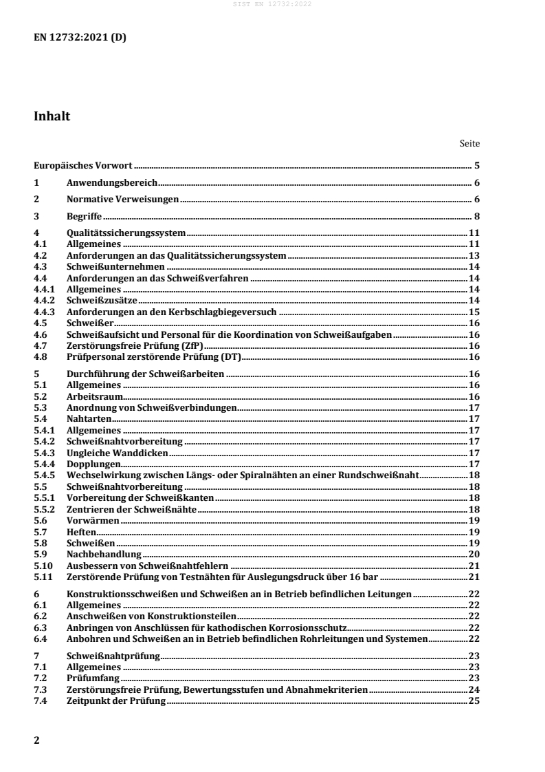
Inhalt
Seite
Europäisches Vorwort . 5
1 Anwendungsbereich . 6
2 Normative Verweisungen . 6
3 Begriffe . 8
4 Qualitätssicherungssystem . 11
4.1 Allgemeines . 11
4.2 Anforderungen an das Qualitätssicherungssystem . 13
4.3 Schweißunternehmen . 14
4.4 Anforderungen an das Schweißverfahren . 14
4.4.1 Allgemeines . 14
4.4.2 Schweißzusätze . 14
4.4.3 Anforderungen an den Kerbschlagbiegeversuch . 15
4.5 Schweißer . 16
4.6 Schweißaufsicht und Personal für die Koordination von Schweißaufgaben . 16
4.7 Zerstörungsfreie Prüfung (ZfP) . 16
4.8 Prüfpersonal zerstörende Prüfung (DT) . 16
5 Durchführung der Schweißarbeiten . 16
5.1 Allgemeines . 16
5.2 Arbeitsraum. 16
5.3 Anordnung von Schweißverbindungen . 17
5.4 Nahtarten . 17
5.4.1 Allgemeines . 17
5.4.2 Schweißnahtvorbereitung . 17
5.4.3 Ungleiche Wanddicken . 17
5.4.4 Dopplungen. 17
5.4.5 Wechselwirkung zwischen Längs- oder Spiralnähten an einer Rundschweißnaht . 18
5.5 Schweißnahtvorbereitung . 18
5.5.1 Vorbereitung der Schweißkanten . 18
5.5.2 Zentrieren der Schweißnähte . 18
5.6 Vorwärmen . 19
5.7 Heften . 19
5.8 Schweißen . 19
5.9 Nachbehandlung . 20
5.10 Ausbessern von Schweißnahtfehlern . 21
5.11 Zerstörende Prüfung von Testnähten für Auslegungsdruck über 16 bar . 21
6 Konstruktionsschweißen und Schweißen an in Betrieb befindlichen Leitungen . 22
6.1 Allgemeines . 22
6.2 Anschweißen von Konstruktionsteilen . 22
6.3 Anbringen von Anschlüssen für kathodischen Korrosionsschutz . 22
6.4 Anbohren und Schweißen an in Betrieb befindlichen Rohrleitungen und Systemen . 22
7 Schweißnahtprüfung . 23
7.1 Allgemeines . 23
7.2 Prüfumfang . 23
7.3 Zerstörungsfreie Prüfung, Bewertungsstufen und Abnahmekriterien . 24
7.4 Zeitpunkt der Prüfung . 25
7.5 Einbinden von Schweißnähten für Auslegungsdruck über 16 bar . 25
7.6 Dokumentation von Prüfergebnissen . 25
7.7 Anforderungen an die Dokumentation . 27
8 Mess-, Regel- und Verdichterstationen . 28
Anhang A (normativ) Qualifikation von Schweißern und Bedienern von mechanisierten
Schweißgeräten für Stahlrohrleitungen . 29
A.1 Allgemeines . 29
A.2 Zusätzliche Anforderungen zu EN ISO 9606-1:2017 und EN ISO 14732:2013 . 29
A.2.1 Geschweißte Länge . 29
A.2.2 Schweißbedingungen . 29
A.2.3 Bestätigung der Gültigkeit . 29
A.2.4 Erneute Überprüfung der Qualifikation der Schweißer . 29
A.2.5 Handfertigkeitsprüfung . 30
A.2.6 Schweißer-Prüfungsbescheinigung . 30
A.2.7 Bezeichnung . 30
A.3 Zusätzliche Anforderungen an Bediener von mechanisierten Schweißgeräten . 30
Anhang B (informativ) Prüfung des Grundwerkstoffs auf Dopplungen . 31
Anhang C (informativ) Beugungslaufzeittechnik (TOFD) . 32
C.1 Allgemeines . 32
C.2 Ergänzende und ersetzende Anforderungen zu EN ISO 10863:2011 . 32
C.2.1 Ergänzung in dem gesamten Dokument EN ISO 10863:2011. 32
C.2.2 Ergänzung zur EN ISO 10863:2011, Abschnitt 3, „Begriffe“ . 32
C.2.3 Ergänzung zu EN ISO 10863:2011, Abschnitt 5, „Prüfklassen“ . 34
C.2.4 Ergänzung zu EN ISO 10863:2011, 7.2.2 „Ultraschall-Prüfköpfe“ . 34
C.2.5 Ersatz von EN ISO 10863:2011, Abschnitt 11, dritter Absatz „Prüfung der Schweißnähte“ . 34
C.2.6 Ersatz von EN ISO 10863:2011, 12.5.2 „Größenbestimmung“ . 34
Anhang D (normativ) Kritische Gesichtspunkte für das Anbohren oder Schweißen an in Betrieb
befindlichen Leitungen. 40
D.1 Allgemeines . 40
D.2 Verfahrensvorschriften . 40
D.3 Aufsicht . 41
D.4 Sicherheitsmaßnahmen . 41
D.5 Schweißzusätze . 42
D.6 Schweißanweisung (WPS) . 42
D.7 Schweißverfahrensprüfung für das Schweißen an in Betrieb befindlichen Leitungen . 42
D.8 Qualifikation der Schweißer . 42
D.9 Schweißnahtvorbereitung der Längsnähte . 42
D.10 Schweißnahtvorbereitung der Rundnähte (Kehlnähte) . 43
D.11 Reparatur . 43
D.12 Zerstörungsfreie Prüfung . 43
D.13 Druckprüfung . 43
D.14 Dokumentation . 43
Anhang E (normativ) AUT-Prüfung der Schweißnähte . 44
E.1 Anwendungsbereich . 44
E.2 Allgemeine Anforderungen . 44
E.2.1 Allgemeines . 44
E.2.2 AUT-Qualitätssicherung . 44
E.2.3 Inhalt der Verfahrensanweisung . 45
E.2.4 Ausrüstung und Komponenten von Ultraschallsystemen . 47
E.2.5 Referenzblöcke . 47
E.2.6 Einrichtung der Aufzeichnung . 48
E.2.7 Umfangsabtastgeschwindigkeit . 48
E.2.8 Software . 49
E.2.9 Referenzlinie, Bandposition und Beschichtungsschnitt . 49
E.2.10 Bediener . 49
E.2.11 Kalibrierung (Einstellung der Empfindlichkeit) . 49
E.3 Inspektion vor Ort . 53
E.4 Anpassungen des AUT-Systems . 54
E.5 Abnahmekriterien Stufe 1 . 54
E.6 Abnahmekriterien Stufe 2 . 56
Anhang F (informativ) Manuelle Prüfung von Schweißverbindungen mit Ultraschall an
Wanddicken von etwa 6 mm bis 8 mm . 60
F.1 Allgemeines . 60
F.2 Entfernungsjustierung . 60
F.3 Empfindlichkeitseinstellung nach der AVG-Methode . 60
Anhang G (normativ) EPRG-Abnahmekriterien . 63
G.1 Allgemeines . 63
G.2 EPRG-Fehlerakzeptanzgrenzen und Fehlergrenzen . 63
G.3 Anforderungen . 63
Anhang H (normativ) Visuelle Abnahmekriterien nach EN ISO 5817:2014 . 69
Anhang I (normativ) Abnahmekriterien der Durchstrahlungsprüfung (RT) nach EN ISO 10675-
1:2016 und EN ISO 5817:2014 . 71
Anhang J (normativ) Alternative Methode und Abnahmekriterien für die UT-Inspektion . 73
J.1 AVG-Methode . 73
J.2 Vergleichskörpermethode . 73
J.3 Allgemeines . 73
Anhang K (informativ) Löten und aluminothermisches Schweißen von Anschlüssen für den
kathodischen Korrosionsschutz . 75
K.1 Verbindungstechniken . 75
K.2 Eignung des Verfahrens . 75
K.3 Qualifikation für die Arbeitsdurchführung . 76
K.4 Durchführung von Bauarbeiten . 76
Anhang L (informativ) Wesentliche technische Änderungen dieser Europäischen Norm
gegenüber der vorherigen Ausgabe . 77
Literaturhinweise . 78
Europäisches Vorwort
Dieses Dokument (EN 12732:2021) wurde vom Technischen Komitee CEN/TC 234 „Gasinfrastruktur“
erarbeitet, dessen Sekretariat von DIN gehalten wird.
Diese Europäische Norm muss den Status einer nationalen Norm erhalten, entweder durch Veröffentlichung
eines identischen Textes oder durch Anerkennung bis Mai 2022, und etwaige entgegenstehende nationale
Normen müssen bis Mai 2022 zurückgezogen werden.
Es wird auf die Möglichkeit hingewiesen, dass einige Elemente dieses Dokuments Patentrechte berühren
können. CEN ist nicht dafür verantwortlich, einige oder alle diesbezüglichen Patentrechte zu identifizieren.
Dieses Dokument ersetzt EN 12732:2013+A1:2014.
Dieses Dokument wurde im Rahmen eines Normungsauftrages erarbeitet, den die Europäische Kommission
und die Europäische Freihandelsassoziation CEN erteilt haben.
In Anhang L sind die wesentlichen technischen Änderungen zwischen diesem Dokument und der
Vorgängerversion enthalten.
Von CEN/TC 234 „Gasinfrastruktur“ wurde eine vollständige Serie von Funktionsnormen erarbeitet, die alle
Teile des Gasversorgungssystems vom Ort der Gaseinspeisung in das Transportsystem bis zum Anschluss
am häuslichen, gewerblichen oder industriellen Gasgerät abdeckt.
Bei der Erstellung dieses Dokuments wurde ein grundlegendes Verständnis der Gasinfrastruktur durch den
Benutzer vorausgesetzt.
Die Gasinfrastruktur ist komplex, und der hohe Stellenwert der Sicherheit, der ihrer Errichtung und
Verwendung beigemessen wird, hat zur Entwicklung sehr detaillierter Arbeitsblätter und
Betriebsanweisungen in den Mitgliedsländern geführt. Diese detaillierten Festlegungen umfassen allgemein
anerkannte Normen der Gastechnik sowie die spezifischen Anforderungen, die durch die gesetzlichen
Strukturen der Mitgliedsländer vorgegeben werden.
CEN/TC 234 wird seine Arbeit fortsetzen und diese Norm in regelmäßigen Abständen an die neuesten
Entwicklungen anpassen.
Rückmeldungen oder Fragen zu diesem Dokument sollten an das jeweilige nationale Normungsinstitut des
Anwenders gerichtet werden. Eine vollständige Liste dieser Institute ist auf den Internetseiten von CEN
abrufbar.
Entsprechend der CEN CENELEC Geschäftsordnung sind die nationalen Normungsinstitute der folgenden
Länder gehalten, diese Europäische Norm zu übernehmen: Belgien, Bulgarien, Dänemark, Deutschland, die
Republik Nordmazedonien, Estland, Finnland, Frankreich, Griechenland, Irland, Island, Italien, Kroatien,
Lettland, Litauen, Luxemburg, Malta, Niederlande, Norwegen, Österreich, Polen, Portugal, Rumänien,
Schweden, Schweiz, Serbien, Slowakei, Slowenien, Spanien, Tschechische Republik, Türkei, Ungarn,
Vereinigtes Königreich und Zypern.
1 Anwendungsbereich
Dieses Dokument enthält Anforderungen für die Herstellung und Prüfung von Schweißverbindungen für die
Errichtung und Änderungen (einschließlich Schweißen an in Betrieb befindlichen Leitungen) von
landverlegten Stahlrohrleitungen und Anlagen, die in der Gasinfrastruktur verwendet werden. Dazu gehören
alle Druckbereiche und aufbereitetes, ungiftiges und nicht korrosives Erdgas nach EN ISO 13686 und
nichtkonventionelle Gase wie (eingespeistes) Biomethan und Wasserstoff, wo:
— die Rohrleitungsteile aus nicht legiertem oder niedrig legiertem Kohlenstoffstahl bestehen;
— alle Leitungen und Anlagen, die sich auf Gewerbe- oder Werksgelände befinden, ausschließlich der
Versorgung solcher Grundstücke dienen und kein wesentlicher Bestandteil der Anlagen für
Betriebsabläufe auf diesem Gelände sind;
— es sich nicht um Leitungen innerhalb von Haus- oder Industrieinstallationen nach EN 1775 oder EN
15001 handelt;
— die Auslegungstemperatur zwischen −40 °C bis einschließlich 120 °C liegt.
Für eingespeistes Biomethan oder Wasserstoff ist eine detaillierte technische Bewertung der funktionellen
Anforderungen erforderlich, um sicherzustellen, dass es keine anderen Bestandteile oder Eigenschaften der
Gase gibt, die die Integrität der Leitung beeinträchtigen können.
Dieses Dokument ist nicht auf Schweißnähte anwendbar, die vor der Veröffentlichung dieses Dokuments
erstellt wurden.
Dieses Dokument legt gemeinsame Grundprinzipien für die Gasinfrastruktur fest. Es wird erwartet, dass
Anwender dieses Dokuments sich dessen bewusst sind, dass detailliertere nationale Normen bzw.
Technische Regeln in den CEN-Mitgliedsländern existieren können.
Dieses Dokument ist für die Anwendung in Verbindung mit diesen nationalen Normen und/oder
Verfahrensregeln vorgesehen, welche die vorstehend genannten Grundsätze darlegen.
Beim Auftreten von Widersprüchen aufgrund restriktiver Anforderungen in nationalen
Gesetzen/Vorschriften als in diesem Dokument gefordert, haben nationale Gesetze/Vorschriften Vorrang
wie in CEN/TR 13737 (alle Teile) dargestellt.
ANMERKUNG CEN/TR 13737 (alle Teile) enthält:
— Klärung relevanter in einem Land anwendbarer Rechtsvorschriften/Regelungen;
— gegebenenfalls restriktivere nationale Anforderungen;
— nationale Anlaufstelle für die neusten Informationen.
2 Normative Verweisungen
Die folgenden Dokumente werden im Text in solcher Weise in Bezug genommen, dass einige Teile davon
oder ihr gesamter Inhalt Anforderungen des vorliegenden Dokuments darstellen. Bei datierten
Verweisungen gilt nur die in Bezug genommene Ausgabe. Bei undatierten Verweisungen gilt die letzte
Ausgabe des in Bezug genommenen Dokuments (einschließlich aller Änderungen).
EN 1708-1, Schweißen — Verbindungselemente beim Schweißen von Stahl — Teil 1: Druckbeanspruchte
Bauteile
EN 10204, Metallische Erzeugnisse — Arten von Prüfbescheinigungen
EN ISO 636, Schweißzusätze — Stäbe, Drähte und Schweißgut zum Wolfram-Inertgasschweißen von
unlegierten Stählen und Feinkornstählen — Einteilung (ISO 636)
EN ISO 2560, Schweißzusätze — Umhüllte Stabelektroden zum Lichtbogenhandschweißen von unlegierten
Stählen und Feinkornstählen — Einteilung (ISO 2560:)
EN ISO 3834-2, Qualitätsanforderungen für das Schmelzschweißen von metallischen Werkstoffen — Teil 2:
Umfassende Qualitätsanforderungen (ISO 3834-2)
EN ISO 5817, Schweißen — Schmelzschweißverbindungen an Stahl, Nickel, Titan und deren Legierungen (ohne
Strahlschweißen) — Bewertungsgruppen von Unregelmäßigkeiten (ISO 5817)
EN ISO 6520-1, Schweißen und verwandte Prozesse — Einteilung von geometrischen Unregelmäßigkeiten an
metallischen Werkstoffen — Teil 1: Schmelzschweißen (ISO 6520-1)
EN ISO 9606-1:2017, Prüfung von Schweißern — Schmelzschweißen — Teil 1: Stähle (ISO 9606-1:2017)
EN ISO 9692-1, Schweißen und verwandte Prozesse — Arten der Schweißnahtvorbereitung — Teil 1:
Lichtbogenhandschweißen, Schutzgasschweißen, Gasschweißen, WIG-Schweißen und Strahlschweißen von
Stählen (ISO 9692-1)
EN ISO 9712, Zerstörungsfreie Prüfung — Qualifizierung und Zertifizierung von Personal der zerstörungsfreien
Prüfung (ISO 9712)
EN ISO 10675-1:2016, Zerstörungsfreie Prüfung von Schweißverbindungen — Zulässigkeitsgrenzen für die
Durchstrahlungsprüfung —Teil 1: Stahl, Nickel, Titan und deren Legierungen (ISO 10675-1:2016)
EN ISO 10863:2011, Zerstörungsfreie Prüfung von Schweißverbindungen — Ultraschallprüfung — Anwendung
der Beugungslaufzeittechnik (TOFD) (ISO 10863:2011)
EN ISO 10893-8, Zerstörungsfreie Prüfung von Stahlrohren — Teil 8: Automatisierte Ultraschallprüfung
nahtloser und geschweißter Stahlrohre zum Nachweis von Dopplungen (ISO 10893-8)
EN ISO 11666, Zerstörungsfreie Prüfung von Schweißverbindungen — Ultraschallprüfung —
Zulässigkeitsgrenzen (ISO 11666)
EN ISO 13588, Zerstörungsfreie Prüfung von Schweißverbindungen — Ultraschallprüfung — Anwendung von
automatisierter phasengesteuerter Array-Technologie (ISO 13588)
EN ISO 14171, Schweißzusätze — Massivdrahtelektroden, Fülldrahtelektroden und Draht-Pulver-
Kombinationen zum Unterpulverschweißen von unlegierten Stählen und Feinkornstählen — Einteilung
(ISO 14171)
EN ISO 14174, Schweißzusätze — Pulver zum Unterpulverschweißen und Elektroschlackeschweißen —
Einteilung (ISO 14174)
EN ISO 14175, Schweißzusätze — Gase und Mischgase für das Lichtbogenschweißen und verwandte Prozesse
(ISO 14175)
EN ISO 14341, Schweißzusätze — Drahtelektroden und Schweißgut zum Metall-Schutzgasschweißen von
unlegierten Stählen und Feinkornstählen — Einteilung (ISO 14341)
EN ISO 14732:2013, Schweißpersonal — Prüfung von Bedienern und Einrichtern zum mechanischen und
automatischen Schweißen von metallischen Werkstoffen (ISO 14732:2013)
EN ISO 15609-1, Anforderung und Qualifizierung von Schweißverfahren für metallische Werkstoffe —
Schweißanweisung — Teil 1: Lichtbogenschweißen (ISO 15609-1)
EN ISO 15614-1, Anforderung und Qualifizierung von Schweißverfahren für metallische Werkstoffe —
Schweißverfahrensprüfung — Teil 1: Lichtbogen- und Gasschweißen von Stählen und Lichtbogenschweißen von
Nickel und Nickellegierungen (ISO 15614-1)
EN ISO 17636-1, Zerstörungsfreie Prüfung von Schweißverbindungen — Durchstrahlungsprüfung — Teil 1:
Röntgen- und Gammastrahlungstechniken mit Filmen (ISO 17636-1)
EN ISO 17636-2, Zerstörungsfreie Prüfung von Schweißverbindungen — Durchstrahlungsprüfung — Teil 2:
Röntgen- und Gammastrahlungstechniken mit digitalen Detektoren (ISO 17636-2)
EN ISO 17637, Zerstörungsfreie Prüfung von Schweißverbindungen — Sichtprüfung von
Schmelzschweißverbindungen (ISO 17637)
EN ISO 17638, Zerstörungsfreie Prüfung von Schweißverbindungen — Magnetpulverprüfung (ISO 17638)
EN ISO 17640, Zerstörungsfreie Prüfung von Schweißverbindungen — Ultraschallprüfung — Techniken,
Prüfklassen und Bewertung (ISO 17640)
EN ISO 18275, Schweißzusätze — Umhüllte Stabelektroden zum Lichtbogenhandschweißen von hochfesten
Stählen — Einteilung (ISO 18275)
EN ISO 19285, Zerstörungsfreie Prüfung von Schweißverbindungen — Phasengesteuertes Array-
Ultraschallprüfung (PAUT) — Zulässigkeitsgrenzen (ISO 19285)
EN ISO 20378, Schweißzusätze — Stäbe zum Gasschweißen von unlegierten und warmfesten Stählen —
Einteilung (ISO 20378)
EN ISO 23279, Zerstörungsfreie Prüfung von Schweißverbindungen — Ultraschallprüfung —
Charakterisierung von Inhomogenitäten in Schweißnähten (ISO 23279)
3 Begriffe
Für die Anwendung dieses Dokuments gelten die folgenden Begriffe.
ISO und IEC stellen terminologische Datenbanken für die Verwendung in der Normung unter den folgenden
Adressen bereit:
— ISO Online Browsing Platform: verfügbar unter https://www.iso.org/obp
— IEC Electropedia: verfügbar unter https://www.electropedia.org/
3.1
Auslegungsdruck
DP, en: design pressure
Druck, auf dem die Konstruktionsberechnungen beruhen
3.2
Auslegungstemperatur
DT, en: design temperature
Temperatur, auf der die Konstruktionsberechnungen beruhen
3.3
rundliche Pore
Gaspore in einer Schweißnaht, nicht länger als dreimal die Breite
3.4
längliche Pore
Gaspore in einer Schweißnaht, länger als dreimal die Breite
3.5
Gas
bei einer Temperatur von 15 °C und Atmosphärendruck (1,013 25 bar absolut) in gasförmigem Zustand
vorliegender Brennstoff
3.6
Gasinfrastruktur
alle Leitungen, Anlagen und Einrichtungen des Gasversorgungssystems vom Ort der Gaseinspeisung in das
Transportsystem bis zum Anschluss am häuslichen, gewerblichen oder industriellen Gasgerät
3.7
Gasverdichterstation
Anlage für:
— den Transport von Gas in Leitungen;
— die Kompression von Gas von einer Leitung in einen Gasspeicher oder umgekehrt
ANMERKUNG 1 zum Begriff: Mehr als eine der beschriebenen Funktionen kann gleichzeitig oder abwechselnd
durchgeführt werden.
3.8
Gasverteilungsnetz
zur Versorgung der Verbraucher erforderliches Leitungssystem einschließlich aller ober- und unterirdischen
Leitungen sowie sonstiger Anlagen
3.9
Gastransport
leitungsgebundene Beförderung von Gas zur Belieferung von Gasverteilungsnetzen oder
Industrieabnehmern
3.10
Hot pass
Lage in einer Zellulosenaht über der Wurzellage einer Umfangsnaht
3.11
Anlage
System zur Gewinnung, Förderung, Aufbereitung, Messung, Regelung, Speicherung oder Übernahme des
transportierten Gases
3.12
Nationale Anforderungen
Anforderungen, die sich aus der geltenden nationalen Gesetzgebung oder nationalen Normen ergeben
3.13
landverlegte Leitung
erdverlegte und/oder oberirdisch verlegte Rohrleitung einschließlich in oder durch Binnenseen oder
Wasserläufe verlegter Abschnitte
3.14
Leitungssystem
System aus Leitungen und den zugehörigen Einrichtungen sowie Stationen bis zur Lieferstelle
ANMERKUNG 1 zum Begriff: Die Leitungen sind hauptsächlich erdverlegt, umfassen aber auch oberirdische Abschnitte.
3.15
Rohrleitungsteile
Teile, aus denen ein Leitungssystem besteht. Die folgenden Elemente sind unterschiedliche
Rohrleitungselemente: Rohr einschließlich kaltgeformter Bögen, Formstücke
ANMERKUNG 1 zum Begriff: Reduzierstücke, T-Stücke, Werkskrümmer und -bögen, Flansche, Verschlusskappen,
Schweißstutzen, mechanische Verbindungen, aus den vorgenannten Bauteilen hergestellte Einrichtungen.
ANMERKUNG 2 zum Begriff: Sammler, Kondensatsammler, Molchschleusen, Mess- und Regelstrecken, Ausrüstung.
ANMERKUNG 3 zum Begriff: Armaturen, Kompensatoren, Isolierstücke, Druckregelgeräte, Pumpen, Verdichter,
zugeordnete Druckbehälter.
3.16
Leitungsbetreiber
privatwirtschaftliches oder öffentliches Unternehmen, das die Erlaubnis besitzt, die Gasinfrastruktur zu
planen, zu bauen und/oder zu betreiben und Instand zu halten, d. h. Gastransportnetzbetreiber (TSO, en: gas
transmission operators) und Gasverteilnetzbetreiber (DSO, en: gas distribution operators)
3.17
Rohrleitungen
Verbund von Rohren und Formstücken
3.18
Druck
Überdruck des Gases innerhalb des Systems, gemessen im statischen Zustand
3.19
Wurzellage
erste Lage in einer einseitig geschweißten Umfangsnaht
3.20
Station
Einrichtung, die dem Betrieb einer Gasinfrastruktur dient
3.21
Prüfdruck
TP, en: test pressure
Druck, dem die Gasinfrastruktur unterworfen wird, um einen sicheren Betrieb sicherzustellen
ANMERKUNG 1 zum Begriff: Der Prüfdruck kann für verschiedene Teile des zu testenden Systems variieren.
3.22
Reparaturschweißen
Ausbesserungsprozess an einem Schweißnahtfehler, der nach der Fertigstellung der Naht festgestellt wurde,
durch Nachschweißen
ANMERKUNG 1 zum Begriff: Die Reparatur kann das vollständige Herausschneiden eines Rohrstücks oder das
Entfernen einer begrenzten Fläche durch Schleifen oder auf anderem Weg sowie durch anschließendes Schweißen
umfassen.
3.23
Schweißer
Person, die den Stabelektrodenhalter, die Schweißpistole oder Schweißbrenner hält und führt
3.24
Schweißsystembediener
Person, die ein mechanisiertes Schweißsystem bedient
3.25
Schweißanweisung
WPS, en: welding procedure specification
Dokument, dass durch ein Verfahren qualifiziert wurde und die erforderlichen Einflussgrößen des
Schweißverfahrens enthält, um die Wiederholbarkeit beim Schweißen in der Fertigung sicherzustellen
3.26
Vergütungslagentechnik
„Temper bead“-Verfahren
Schweißfolge, bei der die Wärmeeinflusszone des Grundwerkstoffes so weich wie möglich gemacht wird
3.27
in Metall gelöster Wasserstoff
HDM, en: hydrogen dissolved in metal
diffusionsfähiger Wasserstoffgehalt in ml in 100 mg Schweißgut
4 Qualitätssicherungssystem
4.1 Allgemeines
Tabelle 1 ordnet die Anwendungsbereiche in Abhängigkeit vom Auslegungsdruck sowie vom eingesetzten
Rohrwerkstoff bestimmten Qualitätsanforderungsstufen zu.
Bei Verwendung dieses Dokumentes muss vom Leitungsbetreiber Folgendes definiert werden; der
zutreffende Absatz ist in Klammern angegeben:
a) anwendbare Qualitätsanforderungsstufe (Anwendungsbereich);
b) anwendbare Qualitätsanforderungen nach Tabelle 2 festgelegt (4.2);
c) spezifische Anforderungen an die visuelle Prüfung (VT, en: visual testing), Personal und/oder
Qualifikation (4.2);
d) anwendbare Normen für die Anforderungen an Schweißverfahren (4.2);
e) notwendige Zugversuche vom reinen Schweißgut (4.4);
f) für die Kategorien B und C werden für die Schweißzusätze Chargen-Zertifikate vorgeschrieben, bei
denen der Leitungsbetreiber die Inhalte der Zertifikate bestimmen muss (4.4.2);
g) für Schweißzusätze, die nicht den aufgeführten europäischen Normen entsprechen, ist
Chargenqualifizierung mit WPQR (en: Welding Procedure Qualification Record) zulässig (4.4.2);
h) wenn Schweißgut mit einer höheren Dehngrenze als die des Grundwerkstoffes gefordert wird (4.4.2);
i) wenn Warmverformung zur Kompensation von Ovalitäten/Kantenversatz bei Materialien mit
≤ 360 MPa (6.2) zulässig ist;
R
t 0,5
j) ob die Schweißnaht nach Abschluss des Schweißens immer abzudecken ist (5.9);
k) für Anforderungen der Stufe D für Reparaturschweißverfahren (5.10);
l) Umfang der Techniken zur zerstörungsfreien Prüfung (7.2);
m) alternative Abnahmekriterien, falls zutreffend (7.3);
n) ob die ZfP-Daten dem Leitungsbetreiber zur Verfügung gestellt werden müssen (7.7);
o) Verfahren, Ausmaß und Akzeptanzkriterien von Schweißnähten im Einsatz (D.12);
Zusätzliche Anforderungen dürfen festgelegt werden, wenn z. B. Folgendes als kritisch betrachtet wird:
— Beanspruchung der Rohrleitungen und Anlagen;
— Werkstoffe;
— Trassenführung;
— Planung oder das Schweißverfahren;
— regionalen Regulierungen.
Tabelle 1 — Zuordnung von Qualitätsanforderungsstufen
Qualitäts-
Anwendungsbereich
anforderungsstufe
≤ 5 bar
a
Werkstoffe der Gruppen 1.1, 1.2 und 1.4 nach CEN ISO/TR 15608
B Streckgrenze der Materialien: R ≤ 360 MPa
t 0,5
Beispiele: Versorgungsleitungen und Hausanschlussleitungen in
Gasverteilungssystemen, Rohrleitungen in Anlagen
> 5 bar ≤ 16 bar
a
Werkstoffe der Gruppen 1.1, 1.2 und 1.4 nach CEN ISO/TR 15608
C Streckgrenze der Materialien: R ≤ 360 MPa
t 0,5
Beispiele: Fernleitungen einschließlich Rohrleitungen in Anlagen und in
Gasverteilungssystemen
b
> 16 bar
Werkstoffe der Gruppen 1, 2 und 3 nach CEN ISO/TR 15608
D
Anwendungsbeispiele: Fernleitungen einschließlich Rohrleitungen in Anlagen und
in Gastransportsystemen
Legende
R ist die Dehngrenze bei 0,5 % der gesamten Dehnung (spezifizierter Mindestwert) nach EN ISO 3183.
t 0,5
ANMERKUNG 1 Die bislang separate Qualitätsanforderungsstufe A für Versorgungsleitungen bis 100 mbar in
EN 12732:2000 ist nun in der Qualitätsanforderungsstufe B enthalten und wurde aus dieser Tabelle gelöscht.
ANMERKUNG 2 Gasinfrastruktur mit einem MOP bis einschließlich 16 bar wird in der Regel der Gasverteilung
zugeordnet.
a
Falls die Werkstoffe außerhalb dieser Spezifikation liegen, muss der Leitungsbetreiber die Anwendbarkeit dieser
Anforderungen überprüfen oder die Qualitätsanforderungsstufe D verwenden.
b
Rohrleitungen, deren tatsächliche Umfangsspannung bei Auslegungsdruck ≤ 30 % von R und deren Betriebsdruck
t 0,5
≤ 24 bar beträgt, können vom Leitungsbetreiber der Qualitätsanforderungsstufe C zugeordnet werden.
4.2 Anforderungen an das Qualitätssicherungssystem
Auf Verlangen des Leitungsbetreibers muss beim Rohrleitungsschweißen ein Qualitätssicherungssystem
angewandt werden. Tabelle 2 gibt einen Überblick über die empfohlenen Qualitätsanforderungen nach
EN ISO 3834 (alle Teile) und ordnet diese den in Tabelle 1 festgelegten Qualitätsanforderungsstufen nach
EN ISO 3834 (alle Teile) zu.
Tabelle 2 — Empfohlene Qualitätsanforderungen
Qualitätsanforderungsstufe
nach Tabelle 1
Anforderungen an:
B C D
Qualitätssicherungssystem nach:
— EN ISO 3834-1 und EN ISO 3834-2 (vollständig) + • •
— EN ISO 3834-1 und EN ISO 3834-3 (Standard) + • •
— EN ISO 3834-1 und EN ISO 3834-4 (elementar) • − −
Schweißaufsicht:
— Personal nach EN ISO 14731:2006
— Schweißfachingenieur + + •
b
— Schweißtechniker + • +
b
— Schweißfachmann • • +
— Schweißpraktiker nach IIW-IAB-252-07 • + −
a
ZfP
— unabhängige, nach EN ISO/IEC 17020 oder EN ISO/IEC 17025
• • •
akkreditierte, ZfP-Firma
— Personal, das ZfP durchführt, nach EN ISO 9712 • • •
— Personal, das Sichtprüfungen durchführt; VT-Stufe 2 oder
+ + •
a
Qualifikation als Schweißpraktiker oder darüber
Schweißanweisung (WPS) nach:
— EN ISO 15609-1 • • •
— EN ISO 15609-2 (bis 100 mbar) • − −
Zulässigkeit des Schweißverfahrens nach einer der
nachgenannten Normen:
— EN ISO 15614-1 Stufe 2 (Schweißverfahrensprüfung) + • •
— EN ISO 15610 (geprüfte Schweißzusätze) • − −
— EN ISO 15611 (vorliegende schweißtechnische Erfahrungen) − − −
b
— EN ISO 15612 (Standardschweißverfahren) + + −
— EN ISO 15613 (vorgezogene Arbeitsprüfung) + + +
Legende: • empfohlen + optional − nicht empfohlen
a
Prüfpersonal kann entweder beim Leitungsbetreiber, Auftragnehmer oder ZfP-Unternehmen angestellt sein.
b
Dies kann bei kleineren Projekten oder bei Werkstoffen R ≤ 360 MPa auch in Qualitätsanforderungsstufe D angewendet
t 0,5
werden.
4.3 Schweißunternehmen
Auf Verlangen des Leitungsbetreibers müssen die Schweißunternehmen ihre Eignung zur Durchführung der
Schweißarbeiten nachweisen. Hierb
...