

EN 12285-2:2005
(Main)Workshop fabricated steel tanks - Part 2: Horizontal cylindrical single skin and double skin tanks for the aboveground storage of flammable and non-flammable water polluting liquids
- Abstract
This document specifies the requirements for metallic shop fabricated cylindrical, horizontal steel tanks, single and double skin for the aboveground storage of water polluting liquids (both flammable and non-flammable) within the following limits:
- from 800 mm up to 3 000 mm nominal diameter and,
- up to a maximum overall length of 6 times the nominal diameter and,
- for liquids with a maximum density of up to 1,9 kg/l and,
- with an operating pressure (Po) of maximum 1,5 bar (abs.) and,
- where double skin tanks with a vacuum leak detection system are used the cinematic viscosity of the stored media shall not exceed 5 ´ 10-3 m2/s.
This document is applicable for normal ambient temperature conditions (- 20 °C to + 50 °C). Where temperatures are outside this range, additional requirements need to be taken into account.
This document is not applicable for the storage of liquids having dangerous good classes listed in Table 1 because of the special dangers involved.
Table 1 - List of dangerous goods the storage of which are not covered by this document
UN-classification Storage media
Class 1 Explosives
Class 4.2 Substances liable to spontaneous combustion
Class 4.3 Substances which in contact with water emit flammable gases
Class 5.2 Organic peroxides
Class 6.2 Infectious substances
Class 7 Radioactive material, hydrocyanic or hydrocyanic solvent liquids, metalcarbonyls, hydrofluoracid, bromide liquids
NOTE The classifications referred to are those adopted by the United Nations Committee of Experts on the Transport of Dangerous Goods (not to be interpreted as tank classes described in 3.1.4).
This document does not cover the installation of tanks which might be subject to local regulations involving pollution control.
- Status
- Published
- Publication Date
- 08-Feb-2005
- Withdrawal Date
- 29-Nov-2006
- Technical Committee
- CEN/TC 265 - Site built metallic tanks for the storage of liquids
- Drafting Committee
- CEN/TC 221/SC 1/WG 2 - Above ground cylindrical tanks
- Current Stage
- 9060 - Closure of 2 Year Review Enquiry - Review Enquiry
- Start Date
- 02-Sep-2026
- Completion Date
- 02-Sep-2026
- Directive
- 305/2011 - Regulation (eu) No 305/2011 of the European Parliament and of the Council of 9 march 2011 laying down harmonised conditions for the marketing of construction products and repealing council directive 89/106/eecOJ Ref: C, C 259 OJ Date: 08-Aug-2014
89/106/EEC - Construction productsOJ Ref: C, C 319 OJ Date: 14-Dec-2005
Buy Documents



Overview
EN 12285-2:2005 (CEN) - Workshop fabricated steel tanks - Part 2 - covers the design, fabrication, testing and marking of workshop-fabricated horizontal cylindrical steel tanks (single-skin and double-skin) for aboveground storage of flammable and non‑flammable water‑polluting liquids. The standard applies to tanks within specific geometric, pressure and temperature limits and supports conformity with European Construction Products requirements and CE marking where applicable.
Key scope limits:
- Nominal diameter: 800 mm to 3 000 mm
- Maximum length: up to 6 × nominal diameter
- Maximum liquid density:1.9 kg/L
- Operating pressure (Po): up to 1.5 bar (abs.)
- For double‑skin tanks with vacuum leak detection, kinematic viscosity ≤ 5 × 10⁻³ m²/s
- Ambient temperature range:−20 °C to +50 °C (outside this range, additional requirements apply)
- Excludes storage of UN classes: 1, 4.2, 4.3, 5.2, 6.2, 7 (see standard for details)
Key Topics
The standard gives prescriptive and performance requirements across manufacturing and quality control, including:
- Materials: acceptable steel grades and delivery documentation
- Design: wall thickness, dished ends, compartmenting, tank classes (A/B/C) and explosion‑pressure considerations
- Fabrication: welding procedure qualification, bolting, lifting lugs, manholes and nozzles
- Supports: saddle and support design for horizontal tanks
- Testing & inspection: hydraulic and interstitial pressure tests (Pt1, Pt2), type testing and factory production control (FPC) procedures
- Durability and reaction to fire: requirements tied to service conditions
- Marking, documentation and conformity assessment: tank certificate, labeling and CE marking guidance (Annex ZA)
Applications
EN 12285-2 is aimed at practical use in:
- Tank manufacturers and fabricators for workshop production of aboveground horizontal tanks
- Design engineers specifying tanks for fuel, chemical and industrial storage (water-polluting liquids within limits)
- Quality assurance and inspection bodies conducting type tests and factory production control
- Purchasers and asset owners who require certified tanks meeting European standards and CE marking
- Environmental and safety managers ensuring appropriate containment and leak detection
Benefits include harmonized safety, repeatable fabrication quality, and clearer conformity paths for aboveground storage tanks used in industrial and commercial settings.
Related standards
- EN 12285-1 (underground tanks)
- EN 13160 series (leak detection)
- EN 13616 (overfill prevention)
- EN 13352 (tank gauges)
- EN 13501-1 (fire classification)
- EN 10025, EN ISO 15614 / 15607 (materials and welding)
For full technical application, consult EN 12285-2:2005 text and the referenced normative documents.
Relations
- Effective Date
- 28-Jan-2026
- Effective Date
- 28-Jan-2026
- Effective Date
- 28-Jan-2026
- Effective Date
- 28-Jan-2026
- Effective Date
- 28-Jan-2026
- Effective Date
- 28-Jan-2026
- Effective Date
- 28-Jan-2026
- Effective Date
- 28-Jan-2026
- Effective Date
- 28-Jan-2026
- Effective Date
- 28-Jan-2026
- Effective Date
- 28-Jan-2026
- Effective Date
- 28-Jan-2026
- Effective Date
- 28-Jan-2026
Buy Documents
Get Certified
Connect with accredited certification bodies for this standard

CIS Institut d.o.o.
Personal Protective Equipment (PPE) certification body. Notified Body NB-2890 for EU Regulation 2016/425 PPE.
Institut za varilstvo d.o.o. (Welding Institute)
Slovenia's leading welding institute since 1952. ISO 3834, EN 1090, pressure equipment certification, NDT personnel, welder qualification. Only IIW Au

Kiwa BDA Testing
Building and construction product certification.
Sponsored listings
Frequently Asked Questions
EN 12285-2:2005 is a standard published by the European Committee for Standardization (CEN). Its full title is "Workshop fabricated steel tanks - Part 2: Horizontal cylindrical single skin and double skin tanks for the aboveground storage of flammable and non-flammable water polluting liquids". This standard covers: This document specifies the requirements for metallic shop fabricated cylindrical, horizontal steel tanks, single and double skin for the aboveground storage of water polluting liquids (both flammable and non-flammable) within the following limits: - from 800 mm up to 3 000 mm nominal diameter and, - up to a maximum overall length of 6 times the nominal diameter and, - for liquids with a maximum density of up to 1,9 kg/l and, - with an operating pressure (Po) of maximum 1,5 bar (abs.) and, - where double skin tanks with a vacuum leak detection system are used the cinematic viscosity of the stored media shall not exceed 5 ´ 10-3 m2/s. This document is applicable for normal ambient temperature conditions (- 20 °C to + 50 °C). Where temperatures are outside this range, additional requirements need to be taken into account. This document is not applicable for the storage of liquids having dangerous good classes listed in Table 1 because of the special dangers involved. Table 1 - List of dangerous goods the storage of which are not covered by this document UN-classification Storage media Class 1 Explosives Class 4.2 Substances liable to spontaneous combustion Class 4.3 Substances which in contact with water emit flammable gases Class 5.2 Organic peroxides Class 6.2 Infectious substances Class 7 Radioactive material, hydrocyanic or hydrocyanic solvent liquids, metalcarbonyls, hydrofluoracid, bromide liquids NOTE The classifications referred to are those adopted by the United Nations Committee of Experts on the Transport of Dangerous Goods (not to be interpreted as tank classes described in 3.1.4). This document does not cover the installation of tanks which might be subject to local regulations involving pollution control.
This document specifies the requirements for metallic shop fabricated cylindrical, horizontal steel tanks, single and double skin for the aboveground storage of water polluting liquids (both flammable and non-flammable) within the following limits: - from 800 mm up to 3 000 mm nominal diameter and, - up to a maximum overall length of 6 times the nominal diameter and, - for liquids with a maximum density of up to 1,9 kg/l and, - with an operating pressure (Po) of maximum 1,5 bar (abs.) and, - where double skin tanks with a vacuum leak detection system are used the cinematic viscosity of the stored media shall not exceed 5 ´ 10-3 m2/s. This document is applicable for normal ambient temperature conditions (- 20 °C to + 50 °C). Where temperatures are outside this range, additional requirements need to be taken into account. This document is not applicable for the storage of liquids having dangerous good classes listed in Table 1 because of the special dangers involved. Table 1 - List of dangerous goods the storage of which are not covered by this document UN-classification Storage media Class 1 Explosives Class 4.2 Substances liable to spontaneous combustion Class 4.3 Substances which in contact with water emit flammable gases Class 5.2 Organic peroxides Class 6.2 Infectious substances Class 7 Radioactive material, hydrocyanic or hydrocyanic solvent liquids, metalcarbonyls, hydrofluoracid, bromide liquids NOTE The classifications referred to are those adopted by the United Nations Committee of Experts on the Transport of Dangerous Goods (not to be interpreted as tank classes described in 3.1.4). This document does not cover the installation of tanks which might be subject to local regulations involving pollution control.
EN 12285-2:2005 is classified under the following ICS (International Classification for Standards) categories: 13.300 - Protection against dangerous goods; 23.020.10 - Stationary containers and tanks. The ICS classification helps identify the subject area and facilitates finding related standards.
EN 12285-2:2005 has the following relationships with other standards: It is inter standard links to EN ISO 15614-1:2017, EN 12285-1:2003, EN 10025-2:2019, EN ISO 9606-1:2017, EN ISO 898-1:2013, EN ISO 15607:2019, EN 10204:2004, EN ISO 9606-2:2004, EN 13501-1:2018, EN 13160-3:2016+A1:2024, EN 13160-3:2016, EN 13160-2:2016+A1:2024, EN 13160-2:2016. Understanding these relationships helps ensure you are using the most current and applicable version of the standard.
EN 12285-2:2005 is associated with the following European legislation: EU Directives/Regulations: 305/2011, 89/106/EEC; Standardization Mandates: M/131. When a standard is cited in the Official Journal of the European Union, products manufactured in conformity with it benefit from a presumption of conformity with the essential requirements of the corresponding EU directive or regulation.
EN 12285-2:2005 is available in PDF format for immediate download after purchase. The document can be added to your cart and obtained through the secure checkout process. Digital delivery ensures instant access to the complete standard document.
Standards Content (Sample)
SLOVENSKI STANDARD
01-maj-2005
V delavnici izdelani rezervoarji iz jekla - 2. del: Ležeči valjasti enoplaščni in
dvoplaščni rezervoarji za nadzemno shranjevanje vnetljivih in nevnetljivih tekočin,
ki onesnažujejo vodo
Workshop fabricated steel tanks - Part 2: Horizontal cylindrical single skin and double
skin tanks for the aboveground storage of flammable and non-flammable water polluting
liquids
Werksgefertigte Tanks aus Stahl - Teil 2: Liegende zylindrische ein- und doppelwandige
Tanks zur oberirdischen Lagerung von brennbaren und nichtbrennbaren
wassergefährdenden Flüssigkeiten
Réservoirs en aciers fabriqués en atelier - Partie 2: Réservoirs horizontaux a simple et
double paroi pour le stockage aérien des liquides inflammables et non inflammables
polluant l'eau
Ta slovenski standard je istoveten z: EN 12285-2:2005
ICS:
13.300 Varstvo pred nevarnimi Protection against dangerous
izdelki goods
23.020.10 Nepremične posode in Stationary containers and
rezervoarji tanks
2003-01.Slovenski inštitut za standardizacijo. Razmnoževanje celote ali delov tega standarda ni dovoljeno.
EUROPEAN STANDARD
EN 12285-2
NORME EUROPÉENNE
EUROPÄISCHE NORM
February 2005
ICS 23.020.10
English version
Workshop fabricated steel tanks - Part 2: Horizontal cylindrical
single skin and double skin tanks for the aboveground storage of
flammable and non-flammable water polluting liquids
Réservoirs en aciers fabriqués en atelier - Partie 2: Werksgefertigte Tanks aus Stahl - Teil 2: Liegende
Réservoirs horizontaux à simple et double paroi pour le zylindrische ein- und doppelwandige Tanks zur
stockage aérien des liquides inflammables et non oberirdischen Lagerung von brennbaren und
inflammables polluant l'eau nichtbrennbaren wassergefährdenden Flüssigkeiten
This European Standard was approved by CEN on 17 December 2004.
CEN members are bound to comply with the CEN/CENELEC Internal Regulations which stipulate the conditions for giving this European
Standard the status of a national standard without any alteration. Up-to-date lists and bibliographical references concerning such national
standards may be obtained on application to the Central Secretariat or to any CEN member.
This European Standard exists in three official versions (English, French, German). A version in any other language made by translation
under the responsibility of a CEN member into its own language and notified to the Central Secretariat has the same status as the official
versions.
CEN members are the national standards bodies of Austria, Belgium, Cyprus, Czech Republic, Denmark, Estonia, Finland, France,
Germany, Greece, Hungary, Iceland, Ireland, Italy, Latvia, Lithuania, Luxembourg, Malta, Netherlands, Norway, Poland, Portugal, Slovakia,
Slovenia, Spain, Sweden, Switzerland and United Kingdom.
EUROPEAN COMMITTEE FOR STANDARDIZATION
COMITÉ EUROPÉEN DE NORMALISATION
EUROPÄISCHES KOMITEE FÜR NORMUNG
Management Centre: rue de Stassart, 36 B-1050 Brussels
© 2005 CEN All rights of exploitation in any form and by any means reserved Ref. No. EN 12285-2:2005: E
worldwide for CEN national Members.
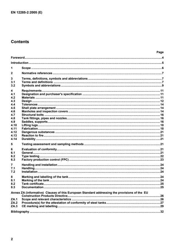
Contents
Page
Foreword.4
Introduction .5
1 Scope .6
2 Normative references .7
3 Terms, definitions, symbols and abbreviations .7
3.1 Terms and definitions .7
3.2 Symbols and abbreviations .9
4 Requirements.11
4.1 Designation and purchaser's specification .11
4.2 Materials .11
4.3 Design .12
4.4 Tolerances .14
4.5 Shell plate arrangement .14
4.6 Manholes and inspection covers .14
4.7 Structural bolts .16
4.8 Tank fittings, pipes and nozzles.16
4.9 Saddles, supports.16
4.10 Lifting lugs.18
4.11 Fabrication.18
4.12 Dangerous substances .21
4.13 Reaction to fire.21
4.14 Durability .21
5 Testing assessment and sampling methods .21
6 Evaluation of conformity.21
6.1 General.21
6.2 Type testing.22
6.3 Factory production control (FPC) .23
7 Handling and installation .24
7.1 Handling.24
7.2 Installation .24
8 Marking and labelling of the tank.24
8.1 Marking of the tank.24
8.2 Tank certificate.25
8.3 Documentation.25
Annex ZA (informative) Clauses of this European Standard addressing the provisions of the EU
Construction Products Directive.26
ZA.1 Scope and relevant characteristics .26
ZA.2 Procedure(s) for the attestation of conformity of steel tanks.27
ZA.3 CE marking and labelling.29
Bibliography .32
Figures
Figure 1 — Example of double skin aboveground tank, symbols.10
Figure 2 — Shell plate arrangement for inner and outer skin.14
Figure 3 — Examples for manholes.15
Figure 4 — Example for a saddle support arrangement.16
Figure 5 — Example for marking .24
Figure ZA.1 — Example CE marking information for a system 3 product.31
Tables
Table 1 — List of dangerous goods the storage of which are not covered by this document .6
Table 2 — Tank classes .8
Table 3 — Nominal wall thickness for inner and outer skin tanks, dished ends and compartment
dished end.13
Table 4 — Dimensions of manhole components.15
Table 5 — Dimensions of welded saddles .17
Table 6 — Dimensions of saddle components.17
Table 7 — Loose saddles.17
Table 8 — Types of welded joints .19
Table 9 — Test pressure P and P .21
t1 t2
Table 10 — Number of units and compliance criteria for initial and further testing .22
Table 11 — Minimum frequency of testing for product testing and evaluation as part of FPC .23
Table ZA.1 — Relevant clauses.27
Table ZA.2 — Attestation of conformity systems.27
Table ZA.3a — Assignment of evaluation of conformity tasks (for system 3).28
Table ZA.3b — Assignment of evaluation of conformity tasks (for system 4).28
Foreword
This document (EN 12285-2:2005) has been prepared by Technical Committee CEN/TC 221 “Shop fabricated
metallic tanks and equipment for storage tanks and for service stations”, the secretariat of which is held by DIN.
This European Standard shall be given the status of a national standard, either by publication of an identical text or
by endorsement, at the latest by August 2005, and conflicting national standards shall be withdrawn at the latest by
November 2006.
This document has been prepared under a mandate given to CEN by the European Commission and the European
1)
Free Trade Association and supports essential requirements of Construction Products Directive (CPD) .
For the relationship with this Directive, see informative Annex ZA, which is an integral Part of this document.
By application of this document presumption is given, that the Essential Safety Requirements of the CPD are met.
According to the CEN/CENELEC Internal Regulations, the national standards organizations of the following
countries are bound to implement this European Standard: Austria, Belgium, Cyprus, Czech Republic, Denmark,
Estonia, Finland, France, Germany, Greece, Hungary, Iceland, Ireland, Italy, Latvia, Lithuania, Luxembourg, Malta,
Netherlands, Norway, Poland, Portugal, Slovakia, Slovenia, Spain, Sweden, Switzerland and United Kingdom.
1) Directive 89/106/EEC of the European Parliament and the Council of 21 December 1988 on the approximation of the laws
of the Member States concerning Construction products (OJEC L 40).
Introduction
This document is part of a family of standards involving shop fabricated tanks and equipment for storage tanks and
for service stations (compare listing below and bibliography). Normal ambient temperatures considered in this
document are -20 °C to +50 °C. Where temperatures are outside this range it could become necessary to consider
further requirements. These could include temperature control measures or material control (see 4.2.2).
CEN/TC 221
Shop fabricated metallic tanks
and
equipment for storage tanks and for service stations
SC 1
Tanks
Underground tanks Aboveground tanks
(EN 12285-1) (EN 12285-2)
SC 2
Equipment
Petrol filling stations
Leak detection systems Overfill prevention devices Tank contents gauges
(EN 13617-1 to -4,
(EN 13160-1 to -7) (EN 13616) (EN 13352)
EN 13012, EN 14125)
1 Scope
This document specifies the requirements for metallic shop fabricated cylindrical, horizontal steel tanks, single and
double skin for the aboveground storage of water polluting liquids (both flammable and non-flammable) within the
following limits:
from 800 mm up to 3 000 mm nominal diameter and,
up to a maximum overall length of 6 times the nominal diameter and,
for liquids with a maximum density of up to 1,9 kg/l and,
with an operating pressure (P ) of maximum 1,5 bar (abs.) and,
o
where double skin tanks with a vacuum leak detection system are used the cinematic viscosity of the stored
-3 2
media shall not exceed 5 × 10 m /s.
This document is applicable for normal ambient temperature conditions (- 20 °C to + 50 °C). Where temperatures are
outside this range, additional requirements need to be taken into account.
This document is not applicable for the storage of liquids having dangerous good classes listed in Table 1 because of
the special dangers involved.
Table 1 — List of dangerous goods the storage of which are not covered by this document
UN-classification Storage media
Class 1 Explosives
Class 4.2 Substances liable to spontaneous combustion
Class 4.3 Substances which in contact with water emit flammable gases
Class 5.2 Organic peroxides
Class 6.2 Infectious substances
Class 7 Radioactive material, hydrocyanic or hydrocyanic solvent liquids, metalcarbonyls, hydrofluoracid,
bromide liquids
NOTE The classifications referred to are those adopted by the United Nations Committee of Experts on the Transport of
Dangerous Goods (not to be interpreted as tank classes described in 3.1.4).
This document does not cover the installation of tanks which might be subject to local regulations involving pollution
control.
2 Normative references
The following referenced documents are indispensable for the application of this document. For dated references,
only the edition cited applies. For undated references, the latest edition of the referenced document (including any
amendments) applies.
EN 287-1, Qualification test of welders — Fusion welding — Part 1: Steels
EN 288–2, Specification and approval of welding procedures for metallic materials — Part 2: Welding procedures
specification for arc welding
EN 10025-2, Hot rolled products of structural steels - Part 2: Technical delivery conditions for non-alloy structural
steels
EN 10051:1991 + A1:1997, Continuously hot-rolled uncoated plate, sheet and strip of non-alloy and alloy steels —
Tolerances on dimensions and shape (includes amendment A1:1997)
EN 10204:2004, Metallic products — Types of inspection documents
EN 12285-1:2003, Workshop fabricated steel tanks — Part 1: Horizontal cylindrical single skin and double skin
tanks for the underground storage of flammable and non-flammable water polluting liquids
EN 13501-1, Fire classification of construction products and building elements — Part 1: Classification using test
data from reaction to fire tests
EN ISO 898-1, Mechanical properties of fasteners of carbon steel and alloy steel — Part 1: Bolts, screws and studs
(ISO 898-1:1999)
EN ISO 15607, Specification and qualification of welding procedures for metallic materials — Part 1: General rules
(ISO 15607:2003)
EN ISO 15614-1, Specification and qualification of welding procedures for metallic materials — Welding procedure
test — Part 1: Arc and gas welding of steels and arc welding of nickel and nickel alloys (ISO 15614-1:2004)
3 Terms, definitions, symbols and abbreviations
3.1 Terms and definitions
For the purposes of this document, the following terms and definitions apply.
3.1.1
tank
workshop fabricated cylindrical containment for the storage of liquids. It is made of steel, equipped with dished
ends and consists of one or more compartments
3.1.2
aboveground tank
tank which is not buried in the ground; (a tank installed in a basement is an aboveground tank)
3.1.3
compartment
single storage fluid space within a tank
3.1.4
tank classes
as defined in Table 2
Table 2 — Tank classes
Tank class Description
Class A for liquids with density up to 1,1 kg/l
Class B for liquids with density up to 1,9 kg/l
Class C for liquids with density up to 1,9 kg/l and explosion pressure shockproof under atmospheric
conditions (see also 3.1.5)
3.1.5
explosion pressure shockproof tank
tank which is designed to withstand an internal explosion without leakage; permanent deformations are
permissible. Where the atmospheric pressure is 1 bar the maximum explosion pressure is measured at 10 bar
(abs.)
3.1.6
tank type
for the purpose of this document two tank types are distinguished:
Type S: Single skin
Type D: Double skin
3.1.7
operating pressure (P )
o
pressure inside the tank above the liquid during operating conditions
3.1.8
test pressure (P )
t1
pressure to which the tank or compartment is subjected for testing
3.1.9
interstitial test pressure (P )
t2
pressure to which the interstitial space between the skins is subjected for testing. It is only applicable for double
skin tanks
3.1.10
nominal volume
storage capacity for which the tank is sold
3.1.11
actual volume
total internal capacity of the tank which is equal to or greater than the nominal volume
NOTE The safe working capacity of the tank should normally not exceed 95 % of the nominal volume for mineral oil
products. For other liquids the safe working capacity conforms to Equation (1).
f = (1)
1 + 35δ
where
f is the percentage of nominal volume (%);
δ is the thermal expansion coefficient of the liquid (K).
3.2 Symbols and abbreviations
For the purpose of this document, the following symbols apply.
Dimensions in mm
a Weld thickness
b Width of the saddle
b Width of compensation plate
d External nominal diameter of the tank
d Inside diameter of the manhole
d Diameter of the manhole cover
e Distance between centre of the saddle and the end of the cylindrical part of the tank
h Length of the straight flange of the dished end
k Length of the saddle base
k Pitch circle diameter of manway bolts
p
l Length of the compartment of a tank without dished ends
c
l Overall length of the tank
o
l Length of the tank without dished ends
z
n Distance of the saddle foot to the bottom of the tank
r Crown radius of dished ends
r Knuckle radius of dished ends
r Knuckle radius of the outer dished end
s Nominal thickness of inner skin and inner dished ends
s Interstitial space
s Nominal thickness of outer skin
s Nominal thickness of outer dished ends
s Nominal thickness of compartment dished ends
s Nominal thickness of manhole flange and cover
s Plate thickness of manhole body
α Angle of the saddle
β Angle of the compensation plate
γ Incline angle for T-joint welding
δ Thermal expansion coefficient of the liquid
Key
1 Weld
Figure 1 — Example of double skin aboveground tank, symbols
4 Requirements
4.1 Designation and purchaser's specification
Example for designation: A tank according to this document with a nominal volume of 50 m and a nominal
diameter d = 2 500 mm, tank class B and type D
Tank EN 12285-2/50/2500/B/D
In addition to the above details the manufacturer shall obtain from the purchaser the following requirements:
a) number of compartments and their volumes;
b) material specification or liquid to be stored;
c) kind of internal and/or external coating, if relevant.
4.2 Materials
4.2.1 General
The manufacturer shall select the tank material in accordance with the purchaser's specific requirements or provide
information with the tank concerning the suitability of the tank material for the storage media (e.g. by reference to
EN 12285-1:2003, Annex B).
4.2.2 Materials for shell, dished ends and manholes
Steel according to EN 10025-2, EN 10028-2, EN 10028-7 or EN 10088-1 may be used if the mechanical properties
are at least equal to those of S 235 JR according to EN 10025-2.
In cases where low temperatures have to be considered (below - 20 °C) at least steel grade S 235 J2G3 according to
EN 10025-2 or equal shall be used and in this case wall-thicknesses shall be 6 mm minimum.
4.2.3 Materials for tank fittings
Materials used for the fabrication of tank fittings if welded to the tank shall be compatible with the tank material.
4.2.4 Consumables
All welding rods/wires and other consumables shall be compatible with the basic material.
4.2.5 Material inspection documentation
Material inspection documents for shell plates and dished ends made of carbon steel according to EN 10025-2 shall
be in accordance with 3.2 of EN 10204:2004 (Test report “type 2.2”), for all other steel qualities they shall be in accor-
dance with 4.1 of EN 10204:2004 (Inspection certificate 3.1 “type 3.1”).
4.3 Design
4.3.1 Forms of construction
Tanks shall be manufactured by using shell plates and dished ends.
4.3.2 Single skin tanks
Single skin tanks shall form an impermeable containment; they also constitute the inner skin of a double skin tank.
4.3.3 Double skin tanks
For double skin tanks, an outer skin is welded around the inner tank, which forms an impermeable self contained
tank. The outer skin shall cover at least 95 % of the nominal volume of the inner tank.
There shall be at least two sockets for the leak detection system and these shall be located at the highest point of
the interstitial space.
The interstitial space shall be connected to a leak detection system in order to permanently monitor the integrity of
the tank. For leak detection systems see EN 13160-1 to -7.
Double wall tanks designed for use with a pressure leak detection system shall have stiffening rings in accordance
with 7.12 of EN 12285-1:2003 or alternative designs which shall have no lesser performance.
4.3.4 Dished ends
Dished ends shall be used for external ends of tanks and to separate compartments.
r ≤ d
The following dimensions shall apply:
1 1
r ≥ d / 30
2 1
4.3.5 Compartments
The nominal wall thickness of dished ends separating the compartments (compartment dished ends) are given in
Table 3. For classes A an B a different form of dished ends separating the compartments is possible, where
r = d but without knuckle radius r and without straight flange.
,
1 1 2
A compartment dished end with a knuckle radius and a straight flange is equivalent to a reinforcement ring at the
same position.
4.3.6 Dimensions
4.3.6.1 Material thickness
The nominal wall thickness of inner tank shell, outer tank shell and dished ends shall be declared by the manufacturer
in rounded millimetres, and shall be at least as given in Table 3.
Table 3 — Nominal wall thickness for inner and outer skin tanks, dished ends and compartment dished end
Dimensions in millimetres
Tank classes Class A Class B Class C
a
Nominal shell thickness
Nominal diameter of the tank
s s s s s s
1 3 1 3 1 3
d
inner skin outer skin inner skin outer skin inner skin outer skin
800 up to 1 600
5 3 5 3 5 3
1 601 up to 2 000
6 3 6 3 6 3
2 001 up to 2 500
6 4 7 4 7 4
2 501 up to 3 000
7 4 9 4 9 4
Nominal wall thickness of dished ends
Nominal diameter of the tank
s s s s s s
1 3 1 3 1 3
d
inner skin outer skin inner skin outer skin inner skin outer skin
800 up to 1 600
5 3 5 3 5 3
1 601 up to 2 000
6 3 6 3 6 3
2 001 up to 2 500
6 5 7 5 7 5
2 501 up to 3 000
7 5 9 5 9 5
Nominal wall thickness of compartment dished ends
Nominal diameter of the tank
d
s s s
5 5 5
800 up to 1 600
5 5 10
1 601 up to 2 000
6 6 14
2 001 up to 2 500
6 7 16
2 501 up to 3 000
7 9 18
a
If loose saddles are used see also Table 7.
4.3.6.2 Outer skin
4.3.6.2.1 Circumferential angle
The outer skin shall enclose at least 300° of the circumference of the tank, leaving not more than 60° on the top
uncovered.
In cases where the manhole diameter exceeds d /2, the manhole shall be provided with an outer skin.
4.3.6.2.2 Interstitial space
The interstitial space gap should be as small as practically possible but suitable for the leak detection system to
function.
4.4 Tolerances
4.4.1 The overall length of the inner tank
The tolerance on the overall length of the tank shall be ± 1 % of the real length stated by the manufacturer.
4.4.2 Wall thickness
The minimum thickness of dished ends after forming shall be at least 92 % of the nominal wall thickness as given in
Table 3. Shell plate thickness shall conform to EN 10051:1991+A1:1997, Table 2.
4.4.3 Circumference of dished ends
+ 6 +10
For the dished ends, the tolerances shall be mm for d ≤ 2 000 mm, and mm for d > 2 000 mm based on
1 1
0 0
the calculated circumference of d .
4.5 Shell plate arrangement
Cross seams shall not be allowed. Longitudinal welds shall not be allowed in the bottom half of the tank.
Shell plate joints shall be offset, having a minimum distance e of five times the wall thickness but not less than
25 mm.
Key
e Minimum distance
Figure 2 — Shell plate arrangement for inner and outer skin
4.6 Manholes and inspection covers
Unless otherwise specified by the purchaser, the tanks shall be equipped with at least one inspection cover per
compartment. In cases where inspection covers are not allowed, the tanks shall have one manhole of at least
d = 600 mm and no part of a compartment shall be more than 10 m from a manhole. Single skin tanks shall
always have a manhole.
The manufacturer shall decide whether manholes (inspection covers, nozzles) shall be of set-through or set-on-
type. Nozzles and flanges shall either be welded inside and outside, or by full penetration.
For the dimensions of the manholes and its components see Table 4.
Gaskets shall be provided and suitable for their purpose.
Table 4 — Dimensions of manhole components
Bolts
Inside Plate thick- Diameter of Pitch circle Bolt hole Flange thickness and Thread Number
diameter ness of cover diameter diameter cover thickness size
manhole body
d d k s
2 3 p 6
s
mm mm mm mm mm
mm
Class B
Class A
and C
a
6 720 680 12 16 32
18 M 16
800 7 920 880 12 20 44
b
7 1 120 1 080 -- 20 48
1 000
a
If a manhole is required and no specification is given by the purchaser this diameter shall be used.
b
For tanks of Class C inside diameters of the manhole (d ) exceeding 800 mm are not permitted.
Instead of the manhole covers shown in the Figure 3 and dimensioned in Table 4, ribbed or embossed covers may
be used in Class A-tanks with a plate thickness at least equal to the thickness of the inner tank s . A ribbed or
embossed cover shall withstand the test pressure P (see Table 9).
t1
Inspection openings shall only be used for tanks of Class A with d ≤ 1 250 mm and tanks of Classes B and C with
d ≤ 1 000 mm. The diameter of the inspection cover shall not be larger than 300 mm and not smaller than
120 mm, and the thickness of the inspection cover shall be equal to the minimum thickness of the inner tank.
Dimensions in millimetres
Key
1 Gasket
2 Set-on nozzle
3 Set-through nozzle
4 Vent or other pressure relief device
Figure 3 — Examples for manholes
4.7 Structural bolts
Bolts used shall be in accordance with EN ISO 898-1, with a property Class being at least 4.6. The material chosen
shall be compatible with the tank material.
4.8 Tank fittings, pipes and nozzles
Tank fittings, pipes and nozzles, for double wall tanks shall be situated on the manhole cover or in the single skin
top of the tank. For tanks of Class C only the set-through nozzles shall be used. For set
...
2003-01.Slovenski inštitut za standardizacijo. Razmnoževanje celote ali delov tega standarda ni dovoljeno.Workshop fabricated steel tanks - Part 2: Horizontal cylindrical single skin and double skin tanks for the aboveground storage of flammable and non-flammable water polluting liquidsRéservoirs en aciers fabriqués en atelier - Partie 2: Réservoirs horizontaux a simple et double paroi pour le stockage aérien des liquides inflammables et non inflammables polluant l'eauWerksgefertigte Tanks aus Stahl - Teil 2: Liegende zylindrische ein- und doppelwandige Tanks zur oberirdischen Lagerung von brennbaren und nichtbrennbaren wassergefährdenden Flüssigkeiten23.020.10UH]HUYRDUMLStationary containers and tanks13.300Varstvo pred nevarnimi izdelkiProtection against dangerous goodsICS:SIST EN 12285-2:2005enTa slovenski standard je istoveten z:EN 12285-2:200501-maj-2005SIST EN 12285-2:2005SLOVENSKI
STANDARD
EUROPEAN STANDARDNORME EUROPÉENNEEUROPÄISCHE NORMEN 12285-2February 2005ICS 23.020.10English versionWorkshop fabricated steel tanks - Part 2: Horizontal cylindricalsingle skin and double skin tanks for the aboveground storage offlammable and non-flammable water polluting liquidsRéservoirs en aciers fabriqués en atelier - Partie 2:Réservoirs horizontaux à simple et double paroi pour lestockage aérien des liquides inflammables et noninflammables polluant l'eauWerksgefertigte Tanks aus Stahl - Teil 2: Liegendezylindrische ein- und doppelwandige Tanks zuroberirdischen Lagerung von brennbaren undnichtbrennbaren wassergefährdenden FlüssigkeitenThis European Standard was approved by CEN on 17 December 2004.CEN members are bound to comply with the CEN/CENELEC Internal Regulations which stipulate the conditions for giving this EuropeanStandard the status of a national standard without any alteration. Up-to-date lists and bibliographical references concerning such nationalstandards may be obtained on application to the Central Secretariat or to any CEN member.This European Standard exists in three official versions (English, French, German). A version in any other language made by translationunder the responsibility of a CEN member into its own language and notified to the Central Secretariat has the same status as the officialversions.CEN members are the national standards bodies of Austria, Belgium, Cyprus, Czech Republic, Denmark, Estonia, Finland, France,Germany, Greece, Hungary, Iceland, Ireland, Italy, Latvia, Lithuania, Luxembourg, Malta, Netherlands, Norway, Poland, Portugal, Slovakia,Slovenia, Spain, Sweden, Switzerland and United Kingdom.EUROPEAN COMMITTEE FOR STANDARDIZATIONCOMITÉ EUROPÉEN DE NORMALISATIONEUROPÄISCHES KOMITEE FÜR NORMUNGManagement Centre: rue de Stassart, 36
B-1050 Brussels© 2005 CENAll rights of exploitation in any form and by any means reservedworldwide for CEN national Members.Ref. No. EN 12285-2:2005: E
Clauses of this European Standard addressing the provisions of the
EU Construction Products Directive.26 ZA.1 Scope and relevant characteristics.26 ZA.2 Procedure(s) for the attestation of conformity of steel tanks.27 ZA.3 CE marking and labelling.29 Bibliography.32
Tables Table 1 — List of dangerous goods the storage of which are not covered by this document.6 Table 2 — Tank classes.8 Table 3 — Nominal wall thickness for inner and outer skin tanks, dished ends and compartment dished end.13 Table 4 — Dimensions of manhole components.15 Table 5 — Dimensions of welded saddles.17 Table 6 — Dimensions of saddle components.17 Table 7 — Loose saddles.17 Table 8 — Types of welded joints.19 Table 9 — Test pressure Pt1 and Pt2.21 Table 10 — Number of units and compliance criteria for initial and further testing.22 Table 11 — Minimum frequency of testing for product testing and evaluation as part of FPC.23 Table ZA.1 — Relevant clauses.27 Table ZA.2 — Attestation of conformity systems.27 Table ZA.3a — Assignment of evaluation of conformity tasks (for system 3).28 Table ZA.3b — Assignment of evaluation of conformity tasks (for system 4).28
1) Directive 89/106/EEC of the European Parliament and the Council of 21 December 1988 on the approximation of the laws of the Member States concerning Construction products (OJEC L 40).
and equipment for storage tanks and for service stations
SC 1 Tanks Underground tanks (EN 12285-1) Aboveground tanks (EN 12285-2)
SC 2 Equipment Leak detection systems (EN 13160-1 to -7) Overfill prevention devices (EN 13616) Tank contents gauges (EN 13352) Petrol filling stations (EN 13617-1 to -4, EN 13012, EN 14125)
NOTE The classifications referred to are those adopted by the United Nations Committee of Experts on the Transport of Dangerous Goods (not to be interpreted as tank classes described in 3.1.4). This document does not cover the installation of tanks which might be subject to local regulations involving pollution control.
3.1.5 explosion pressure shockproof tank tank which is designed to withstand an internal explosion without leakage; permanent deformations are permissible. Where the atmospheric pressure is 1 bar the maximum explosion pressure is measured at 10 bar (abs.) 3.1.6 tank type for the purpose of this document two tank types are distinguished: Type S: Single skin Type D: Double skin 3.1.7 operating pressure (Po) pressure inside the tank above the liquid during operating conditions 3.1.8 test pressure (Pt1) pressure to which the tank or compartment is subjected for testing 3.1.9 interstitial test pressure (Pt2) pressure to which the interstitial space between the skins is subjected for testing. It is only applicable for double skin tanks 3.1.10 nominal volume storage capacity for which the tank is sold 3.1.11 actual volume total internal capacity of the tank which is equal to or greater than the nominal volume NOTE The safe working capacity of the tank should normally not exceed 95 % of the nominal volume for mineral oil products. For other liquids the safe working capacity conforms to Equation (1). δ351100+=f
(1) where
f is the percentage of nominal volume (%);
δ is the thermal expansion coefficient of the liquid (K).
External nominal diameter of the tank d2
Inside diameter of the manhole d3
Diameter of the manhole cover e1 Distance between centre of the saddle and the end of the cylindrical part of the tank h1 Length
of the straight flange of the dished end k1 Length of the saddle base kp Pitch circle diameter of manway bolts lc Length of the compartment of a tank without dished ends lo Overall length of the tank lz
Length of the tank without dished ends n1
Distance of the saddle foot to the bottom of the tank r1
Crown radius of dished ends r2
Knuckle radius of dished ends r3
Knuckle radius of the outer dished end s1 Nominal thickness of inner skin and inner dished ends s2 Interstitial space s3 Nominal thickness of outer skin s4 Nominal thickness of outer dished ends s5 Nominal thickness of compartment dished ends s6 Nominal thickness of manhole flange and cover s7 Plate thickness of manhole body
Angle of the saddle β Angle of the compensation plate γ Incline angle for T-joint welding
δ
Thermal expansion coefficient of the liquid
Key 1 Weld Figure 1 — Example of double skin aboveground tank, symbols
In addition to the above details the manufacturer shall obtain from the purchaser the following requirements: a) number of compartments and their volumes; b) material specification or liquid to be stored; c) kind of internal and/or external coating, if relevant. 4.2 Materials 4.2.1 General The manufacturer shall select the tank material in accordance with the purchaser's specific requirements or provide information with the tank concerning the suitability of the tank material for the storage media (e.g. by reference to EN 12285-1:2003, Annex B). 4.2.2 Materials for shell, dished ends and manholes Steel according to EN 10025-2, EN 10028-2, EN 10028-7 or EN 10088-1 may be used if the mechanical properties are at least equal to those of S 235 JR according to EN 10025-2. In cases where low temperatures have to be considered (below - 20 °C) at least steel grade S 235 J2G3 according to EN 10025-2 or equal shall be used and in this case wall-thicknesses shall be 6 mm minimum. 4.2.3 Materials for tank fittings Materials used for the fabrication of tank fittings if welded to the tank shall be compatible with the tank material. 4.2.4 Consumables All welding rods/wires and other consumables shall be compatible with the basic material. 4.2.5 Material inspection documentation Material inspection documents for shell plates and dished ends made of carbon steel according to EN 10025-2 shall be in accordance with 3.2 of EN 10204:2004 (Test report “type 2.2”), for all other steel qualities they shall be in accor-dance with 4.1 of EN 10204:2004 (Inspection certificate 3.1 “type 3.1”).
s5
s5
800 up to 1 600 5
1 601 up to 2 000 6
2 001 up to 2 500 6
2 501 up to 3 000 7
a If loose saddles are used see also Table 7.
4.3.6.2 Outer skin 4.3.6.2.1 Circumferential angle The outer skin shall enclose at least 300° of the circumference of the tank, leaving not more than 60° on the top uncovered. In cases where the manhole diameter exceeds d1/2, the manhole shall be provided with an outer skin. 4.3.6.2.2 Interstitial space The interstitial space gap should be as small as practically possible but suitable for the leak detection system to function.
Key e Minimum distance Figure 2 — Shell plate arrangement for inner and outer skin 4.6 Manholes and inspection covers Unless otherwise specified by the purchaser, the tanks shall be equipped with at least one inspection cover per compartment. In cases where inspection covers are not allowed, the tanks shall have one manhole of at least d2 = 600 mm and no part of a compartment shall be more than 10 m from a manhole. Single skin tanks shall always have a manhole. The manufacturer shall decide whether manholes (inspection covers, nozzles) shall be of set-through or set-on-type. Nozzles and flanges shall either be welded inside and outside, or by full penetration. For the dimensions of the manholes and its components see Table 4. Gaskets shall be provided and suitable for their purpose.
Bolts Inside diameter d2 mm Plate thick-ness of manhole body s7 mm Diameter of cover d3 mm Pitch circle diameter kp mm Bolt hole diameter
mm Flange thickness and cover thickness s6 mm Thread size
Number
Class A
Class B and C
600 a 6 720 680 12 16 32 800 7 920 880 12 20 44 1 000 b 7 1 120 1 080
18 -- 20
M 16
48 a If a manhole is required and no specification is given by the purchaser this diameter shall be used. b For tanks of Class C inside diameters of the manhole (d2) exceeding 800 mm are not permitted.
Instead of the manhole covers shown in the Figure 3 and dimensioned in Table 4, ribbed or embossed covers may be used in Class A-tanks with a plate thickness at least equal to the thickness of the inner tank s1. A ribbed or embossed cover shall withstand the test pressure Pt1 (see Table 9). Inspection openings shall only be used for tanks of Class A with d1 ≤ 1 250 mm and tanks of Classes B and C with d1 ≤ 1 000 mm. The diameter of the inspection cover shall not be larger than 300 mm and not smaller than
120 mm, and the thickness of the inspection cover shall be equal to the minimum thickness of the inner tank.
Dimensions in millimetres
Key 1 Gasket 2 Set-on nozzle 3 Set-through nozzle 4 Vent or other pressure relief device Figure 3 — Examples for manholes
...