

EN 12299:2024+A1:2026
(Main + Amendment)Railway applications - Ride comfort for passengers - Measurement and evaluation
- Abstract
The purpose of this document is to provide methods for quantifying the ride comfort of a passenger in a rail vehicle in response to the track sections it is operated over.
The methods aim to quantify the effects of vehicle body motions on ride comfort and to make the assessment of passenger comfort predictable, repeatable, objective and meaningful.
The methods and comfort scales are validated for people of good health.
This document applies to passengers in rail vehicles operating on heavy rail networks.
This document applies to measurements of motions. It also applies to simulated motions. Guidance is provided on:
- which method described within the document should be used for different scenarios;
- typical values for different comfort levels;
- the application of simulation.
This document excludes health and safety issues, non-passenger carrying vehicles, vehicle homologation and safety, limit values, motion sickness, discomfort caused by accelerating and braking, design guidelines and measurement technology.
- Status
- Published
- Publication Date
- 13-Oct-2026
- Technical Committee
- CEN/TC 256 - Railway applications
- Drafting Committee
- CEN/TC 256/WG 7 - Ride comfort
- Current Stage
- 6060 - Definitive text made available (DAV) - Publishing
- Start Date
- 14-Oct-2026
- Due Date
- 27-Aug-2027
- Completion Date
- 14-Oct-2026

EN 12299:2024+A1:2026 is a CEN European Standard on railway ride comfort for passengers. It specifies methods for measuring and evaluating the comfort experienced in rail vehicles from vehicle-body motions over the track they run on, for passenger vehicles on heavy rail networks. The methods and comfort scales are validated for people of good health, and the document is meant for objective comfort assessment in testing, specification and reporting.
What does EN 12299:2024+A1:2026 specify?
EN 12299:2024+A1:2026 specifies methods for quantifying passenger ride comfort from measured or simulated vehicle motions. It gives guidance on choosing the appropriate method for different situations, typical values for comfort levels, and the use of simulation.
The scope is limited to passengers in rail vehicles operating on heavy rail networks. It excludes health and safety issues, non-passenger carrying vehicles, vehicle homologation and safety, limit values, motion sickness, discomfort caused by accelerating and braking, design guidelines and measurement technology.
The document is organised into clauses 1 to 9, followed by annexes A to K.
| Annex | What it covers |
|---|---|
| Annex A | Reference system for vehicle body and passenger body directions |
| Annex B | Measurement techniques and seat measuring devices |
| Annex C | Weighting curves and filter functions |
| Annex D | Guidance for specifying vehicle performance with respect to ride comfort |
| Annex E | Vehicle assessment with respect to ride comfort |
| Annex F | Presentation of the test report |
| Annex G | Guidance for applying direct tests |
| Annex H | Workflow for calculating RMS from acceleration time series |
| Annex I | Determining quantities used in the calculations |
| Annex J | Guidance for using simulation |
| Annex K | Unit value for the mean comfort index |
What are the key requirements of EN 12299:2024+A1:2026?
EN 12299:2024+A1:2026 centres on four comfort evaluation routes: mean comfort, continuous comfort, comfort on curve transitions, and comfort on discrete events. It also sets the measurement basis, the reference system, the weighting curves, and the reporting structure needed to make results repeatable and comparable.
Measurement basis and comfort indices
Clause 6 defines the standard method for mean comfort and the complete method for mean comfort. The standard method uses accelerations measured at the floor interface, while the complete method also uses seat and other interfaces for seated passengers. In practice, this means a laboratory or test team can choose a simpler vehicle-level measure or a more detailed passenger-level measure depending on the purpose of the test.
Clause 6 also defines continuous comfort as a set of 5 s root mean square (RMS) values of frequency-weighted acceleration in the longitudinal, lateral and vertical directions. This is an intermediate step in the standard mean-comfort method and also a standalone comfort indicator. Because the method filters out quasi-static curve effects, it is best suited to predominantly straight running.
Test conditions and signal processing
Clause 6 requires selection of test sections, test speed, wheel-rail contact geometry and vehicle condition. These conditions matter because the comfort result depends strongly on the route, speed and vehicle state, not only on the vehicle itself.
The document requires digitisation with suitable anti-aliasing filtering, frequency weighting, and sliding RMS calculation over 5 s windows. The sliding step may be the sampling interval, a fraction of 5 s, or 5 s for compatibility with earlier results. For mean comfort, the calculation uses 5 min test zones and percentile values from the 5 s RMS distribution.
Curve transitions and discrete events
Clause 7 defines comfort on curve transitions, expressed as the percentage of dissatisfied passengers for an individual transition. The method uses lateral acceleration, lateral jerk and roll velocity, and it is intended for situations where the transition itself dominates passenger perception. For vehicle assessment, it is stated to apply to tilting trains only.
Clause 7 also includes an alternative sliding form of the curve-transition index over 3 s. This helps produce a continuous time history without needing track start and end points in advance. In practice, that makes it useful for scanning a route for relevant transitions.
Clause 8 defines comfort on discrete events, again as a percentage of dissatisfied passengers. It uses a 2 s time window and combines peak-to-peak lateral acceleration with mean lateral acceleration level. This is aimed at local disturbances such as switches, crossings, bridges and similar events.
Reference system, measurement points and weighting
Annex A defines the local vehicle-body reference system, with the origin on the floor between the bogie centre pivots and x, y, z axes aligned longitudinally, laterally and vertically. Annex B then specifies measuring techniques and seat measuring devices. This matters because sensor orientation and location directly affect the resulting comfort index.
Annex C gives the weighting curves and filter functions used to prepare the signals before calculation. The document states that the weighting curves for vertical, horizontal and other directions are used to reflect the way passengers respond differently to vibration by frequency. For a user, that means the measured acceleration is not taken raw - it is shaped before it becomes a comfort index.
Vehicle assessment and interpretation
Annex E sets out vehicle assessment with respect to ride comfort. It allows the standard mean-comfort method and continuous comfort to be used for vehicle assessment, and it also allows curve-transition comfort for tilting vehicle assessment under the stated conditions. It also asks for the most detailed available description of track geometric quality so the vehicle contribution can be separated from the track input as far as possible.
Clause 9 provides interpretation scales. It gives a five-level scale for the mean comfort index, a scale for continuous comfort in lateral and vertical directions, and an interpretation of curve-transition and discrete-event indices as percentages of dissatisfied passengers. In practice, these scales turn calculated numbers into a comfort judgement that can be used for comparison or reporting.
What terms does EN 12299:2024+A1:2026 define?
- Passenger - a person travelling in a rail vehicle without transport-related activities.
- Ride comfort - the overall sensation caused by motions transmitted through the vehicle body to the passenger.
- Mean comfort - a comfort level evaluated over a long period, at least several minutes.
- Continuous comfort - a short-term comfort measure based on continuously updated RMS values of weighted accelerations.
- Comfort on curve transitions - a comfort evaluation for a perceived curve transition, expressed as the percentage of dissatisfied passengers.
- Comfort on discrete events - a comfort evaluation for a perceived transient acceleration, also expressed as the percentage of dissatisfied passengers.
- Reference system - the local vehicle-body coordinate system used for the measurements and calculations.
- Test zone - a 5 min period used for mean comfort evaluation.
Who uses EN 12299:2024+A1:2026?
EN 12299:2024+A1:2026 is used by railway vehicle manufacturers, rolling stock integrators, test laboratories, operators and assessment teams. They use it to measure comfort, compare vehicle designs, check service comfort on a route, and prepare test reports.
It is also relevant to engineers and quality managers who need to specify ride comfort targets or interpret comfort data. Annex D is written for that purpose, because it links route knowledge, vehicle condition and comfort evaluation into a practical specification context.
For tilting-train projects, the document is especially relevant to curve-transition comfort. For vehicle and track monitoring, it can also support the interpretation of repeated comfort measurements over time.
What changed in EN 12299:2024+A1:2026 from the previous edition?
EN 12299:2024+A1:2026 supersedes EN 12299:2024. The foreword also states the significant technical changes compared with EN 12299:2009.
The listed changes are:
- the scope was revised
- normative references were updated
- Clause 3, terms and definitions, was updated
- Clause 4, symbols, units and abbreviations, was revised
- Clause 5, general description, was revised
- Clause 6, mean comfort and continuous comfort, was revised
- Clause 7, comfort on curve transitions, was updated
- Clause 8, comfort on discrete events, was revised
- Clause 9, guide for the interpretation of the results, was updated
- Annex B, measurement techniques, was updated
- Annex C, weighting curves, was updated
- new Annex D was added
- the previous Annex D was revised and renamed Annex F
- Annex E was revised
- the previous Annex F was revised and renamed Annex G
- Annex H was renamed Annex I
- new Annexes H, J and K were added
Which standards are used with EN 12299:2024+A1:2026?
Clause 2 names EN 15663 as the normative reference. It provides vehicle reference masses, which are needed when the document discusses loading condition and operational mass in working order.
Other standards and series are used in the annexes as companions to the method:
- EN 13848 series - used in Annex E for describing track geometric quality, including track geometry indices and classes
- EN 13848-1 and EN 13848-6 - used in Annex E for characterising track geometry and track quality classes
- EN 15302 - used for wheel-rail contact geometry parameters
- EN 14363:2016+A2:2022 - used in Annex J as the main reference point for simulation practice and validation context
- ISO 8002 - used in Annex F for reporting measured data
- EN ISO 8041 series and ISO 2631-1 - used in Annex C for vibration measurement and weighting-curve context
- EN ISO 5353 - used in Annex B for the Seat Index Point reference when positioning seat-back measurements
What does the EN 12299:2024+A1:2026 document contain?
EN 12299:2024+A1:2026 contains the full calculation and reporting framework for ride comfort testing, including the reference system, weighting curves, test setup, and reporting guidance. It does not just state comfort indices - it also shows how to measure and process the signals that produce them.
The document includes formulas for the 5 s RMS workflow, percentile handling, continuous comfort, mean comfort, comfort on curve transitions and comfort on discrete events. It also includes tables of symbols, units, abbreviations and determining quantities.
Annex B includes figures for seat pan and seat back measuring devices. Annex C includes frequency-response diagrams and tolerance diagrams for the weighting curves. Annex F lays out report content, including time series, statistical results, comfort evaluation and spectral analyses.
Annex H shows the workflow for calculating RMS from measured or simulated acceleration time series. Annex I summarises the determining quantities for the different comfort methods. Annex K provides worked examples for simplifying mean comfort into a unit value, using average, percentile and maximum-based approaches.
Relations
- Merged From
EN 12299:2024 - Railway applications - Ride comfort for passengers - Measurement and evaluation - Effective Date
- 29-Jul-2026
- Effective Date
- 05-Aug-2026
- Effective Date
- 05-Aug-2026
- Effective Date
- 05-Aug-2026
- Effective Date
- 05-Aug-2026
Get Certified
Connect with accredited certification bodies for this standard

IRIS Certification (UNIFE)
International Railway Industry Standard certification.

TÜV SÜD Rail GmbH
TÜV SÜD railway certification services.

Bureau Veritas Railway Certification
Railway and transportation certification.
Sponsored listings
Frequently Asked Questions
EN 12299:2024+A1:2026 is a standard published by the European Committee for Standardization (CEN). Its full title is "Railway applications - Ride comfort for passengers - Measurement and evaluation". This standard covers: The purpose of this document is to provide methods for quantifying the ride comfort of a passenger in a rail vehicle in response to the track sections it is operated over. The methods aim to quantify the effects of vehicle body motions on ride comfort and to make the assessment of passenger comfort predictable, repeatable, objective and meaningful. The methods and comfort scales are validated for people of good health. This document applies to passengers in rail vehicles operating on heavy rail networks. This document applies to measurements of motions. It also applies to simulated motions. Guidance is provided on: - which method described within the document should be used for different scenarios; - typical values for different comfort levels; - the application of simulation. This document excludes health and safety issues, non-passenger carrying vehicles, vehicle homologation and safety, limit values, motion sickness, discomfort caused by accelerating and braking, design guidelines and measurement technology.
The purpose of this document is to provide methods for quantifying the ride comfort of a passenger in a rail vehicle in response to the track sections it is operated over. The methods aim to quantify the effects of vehicle body motions on ride comfort and to make the assessment of passenger comfort predictable, repeatable, objective and meaningful. The methods and comfort scales are validated for people of good health. This document applies to passengers in rail vehicles operating on heavy rail networks. This document applies to measurements of motions. It also applies to simulated motions. Guidance is provided on: - which method described within the document should be used for different scenarios; - typical values for different comfort levels; - the application of simulation. This document excludes health and safety issues, non-passenger carrying vehicles, vehicle homologation and safety, limit values, motion sickness, discomfort caused by accelerating and braking, design guidelines and measurement technology.
EN 12299:2024+A1:2026 is classified under the following ICS (International Classification for Standards) categories: 45.060.20 - Trailing stock. The ICS classification helps identify the subject area and facilitates finding related standards.
EN 12299:2024+A1:2026 has the following relationships with other standards: It is inter standard links to EN 12299:2024, EN 15273-2:2013, EN 13129-1:2002, EN 15827:2011, EN 15273-2:2009. Understanding these relationships helps ensure you are using the most current and applicable version of the standard.
EN 12299:2024+A1:2026 is available in PDF format for immediate download after purchase. The document can be added to your cart and obtained through the secure checkout process. Digital delivery ensures instant access to the complete standard document.
Standards Content (Sample)
SLOVENSKI STANDARD
01-december-2026
Nadomešča:
SIST EN 12299:2024
Železniške naprave - Udobnost vožnje potnikov - Meritve in vrednotenje (vključno
z dopolnilom A1)
Railway applications - Ride comfort for passengers - Measurement and evaluation
Bahnanwendungen - Fahrkomfort für Fahrgäste - Messung und Auswertung
Applications ferroviaires - Confort de marche des voyageurs - Mesurage et évaluation
Ta slovenski standard je istoveten z: EN 12299:2024+A1:2026
ICS:
13.160 Vpliv vibracij in udarcev na Vibration and shock with
ljudi respect to human beings
45.060.20 Železniški vagoni Trailing stock
2003-01.Slovenski inštitut za standardizacijo. Razmnoževanje celote ali delov tega standarda ni dovoljeno.
EN 12299:2024+A1
EUROPEAN STANDARD
NORME EUROPÉENNE
October 2026
EUROPÄISCHE NORM
ICS 45.060.20 Supersedes EN 12299:2024
English Version
Railway applications - Ride comfort for passengers -
Measurement and evaluation
Applications ferroviaires - Confort de marche des Bahnanwendungen - Fahrkomfort für Fahrgäste -
voyageurs - Mesurage et évaluation Messung und Auswertung
This European Standard was approved by CEN on 17 October 2026.
CEN members are bound to comply with the CEN/CENELEC Internal Regulations which stipulate the conditions for giving this
European Standard the status of a national standard without any alteration. Up-to-date lists and bibliographical references
concerning such national standards may be obtained on application to the CEN-CENELEC Management Centre or to any CEN
member.
This European Standard exists in three official versions (English, French, German). A version in any other language made by
translation under the responsibility of a CEN member into its own language and notified to the CEN-CENELEC Management
Centre has the same status as the official versions.
CEN members are the national standards bodies of Austria, Belgium, Bulgaria, Croatia, Cyprus, Czech Republic, Denmark,
Estonia, Finland, France, Germany, Greece, Hungary, Iceland, Ireland, Italy, Latvia, Lithuania, Luxembourg, Malta, Netherlands,
Norway, Poland, Portugal, Republic of North Macedonia, Romania, Serbia, Slovakia, Slovenia, Spain, Sweden, Switzerland, Türkiye
and United Kingdom.
EUROPEAN COMMITTEE FOR STANDARDIZATION
C O M I T É E U R O P É E N D E N O R M A L I S A T I O N
E U R O P Ä I S C H E S K O M I T E E F Ü R N O R M U N G
CEN-CENELEC Management Centre: Rue de la Science 23, B-1040 Brussels
© 2026 CEN All rights of exploitation in any form and by any means reserved Ref. No. EN 12299:2024+A1:2026 E
worldwide for CEN national Members.
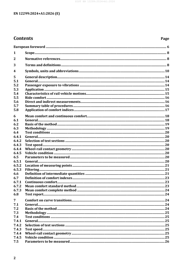
Contents Page
European foreword . 6
1 Scope . 8
2 Normative references . 8
3 Terms and definitions . 8
4 Symbols, units and abbreviations . 10
5 General description. 14
5.1 General. 14
5.2 Passenger exposure to vibrations . 14
5.3 Application . 15
5.4 Characteristics of rail vehicle motions . 15
5.5 Ride comfort . 16
5.6 Direct and indirect measurements . 16
5.7 Summary table of procedures . 16
5.8 Application of comfort indices . 17
6 Mean comfort and continuous comfort . 18
6.1 General. 18
6.2 Basis of the method . 19
6.3 Methodology . 19
6.4 Test conditions . 20
6.4.1 General. 20
6.4.2 Selection of test sections . 20
6.4.3 Test speed . 20
6.4.4 Wheel-rail contact geometry . 20
6.4.5 Vehicle condition . 20
6.5 Parameters to be measured . 20
6.5.1 General. 20
6.5.2 Location of measuring points . 21
6.5.3 Filtering . 21
6.6 Definition of intermediate quantities . 21
6.7 Definition of comfort indexes . 23
6.7.1 Continuous comfort. 23
6.7.2 Mean comfort standard method . 23
6.7.3 Mean comfort complete method . 24
6.8 Test report . 24
7 Comfort on curve transitions . 24
7.1 General. 24
7.2 Basis of the method . 24
7.3 Methodology . 25
7.4 Test conditions . 25
7.4.1 General. 25
7.4.2 Selection of test sections . 25
7.4.3 Test speed . 25
7.4.4 Wheel-rail contact geometry . 25
7.4.5 Vehicle condition . 25
7.5 Parameters to be measured . 26
7.5.1 General . 26
7.5.2 Location of measuring points . 26
7.5.3 Filtering . 26
7.6 Definition of intermediate quantities . 26
7.6.1 Symbols and indices . 26
7.6.2 Averaging procedure . 27
7.6.3 Identification of transition periods. 27
7.6.4 Intermediate quantities . 28
7.7 Definition of comfort index P . 30
CT
7.8 Alternative comfort index ‘sliding P over 3 s’ . 30
CT
7.9 Test report . 33
8 Comfort on discrete events . 33
8.1 General . 33
8.2 Basis of the method . 34
8.3 Methodology . 34
8.4 Test conditions . 34
8.4.1 General . 34
8.4.2 Selection of test sections . 34
8.4.3 Test speed . 35
8.4.4 Wheel-rail contact geometry . 35
8.4.5 Vehicle condition . 35
8.5 Parameters to be measured . 35
8.5.1 General . 35
8.5.2 Location of measuring points . 35
8.5.3 Filtering . 35
8.6 Definition of quantities . 35
8.6.1 Symbols and indices . 35
8.6.2 Averaging procedure to obtain the mean value . 36
8.6.3 Maximum peak to peak value. 36
8.7 Definition of comfort index P . 37
DE
8.8 Test report . 37
9 Guide for the interpretation of results . 37
9.1 General . 37
9.2 Mean comfort . 37
9.3 Continuous comfort . 38
9.4 Comfort on curve transitions . 38
9.5 Comfort on discrete events . 39
Annex A (normative) Reference system . 40
Annex B (normative) Measurement techniques. 42
B.1 General . 42
B.2 Measuring equipment . 42
B.2.1 General . 42
B.2.2 Transducers and signal amplifiers . 42
B.2.3 Recording equipment . 43
B.2.4 Fixing transducers to the floor . 43
B.3 Seat measuring devices and their applications . 43
Annex C (normative) Weighting curves . 46
C.1 General. 46
C.2 Filter functions. 47
C.2.1 General. 47
C.2.2 Band-limiting filter . 47
C.2.3 Acceleration to velocity transition . 48
C.2.4 Upward gradient . 48
C.2.5 Overall frequency weighting. 48
C.2.6 Reduction of the upper limit of the frequency range in vertical direction . 48
C.3 Tolerances . 48
C.4 Diagrams . 50
Annex D (informative) Specifying the vehicle performance with regard to ride comfort . 54
D.1 General. 54
D.2 Knowledge of route for comfort assessment . 54
D.3 Track condition . 54
D.4 Specification of vehicle conditions . 55
D.5 General specification . 55
Annex E (normative) Vehicle assessment with respect to ride comfort . 56
E.1 General. 56
E.2 Track geometric quality . 56
E.3 Test conditions . 57
E.3.1 Selection of test sections and test zones . 57
E.3.2 Test speed . 57
E.3.3 Wheel-rail contact geometry . 57
E.3.4 Vehicle condition . 57
E.4 Acceptable modifications of the methods for the continuous or mean comfort evaluation
............................................................................................................................................................................. 58
E.5 Test report . 60
Annex F (informative) Presentation of test report . 61
F.1 General. 61
F.2 Aim of test . 61
F.3 Test performer . 61
F.4 References . 61
F.5 Test conditions . 61
F.5.1 General information . 61
F.5.2 Vehicle . 62
F.5.3 Seat (for mean comfort complete method) . 62
F.5.4 Seat occupant (for mean comfort complete method) . 62
F.5.5 Track . 62
F.5.6 Speed profile . 63
F.5.7 Test configurations . 63
F.6 Measurements and processing . 63
F.6.1 Measurements . 63
F.6.2 Processing . 63
F.6.3 Deviations . 63
F.7 Report on mean comfort and continuous comfort . 63
F.7.1 General . 63
F.7.2 Time series . 63
F.7.3 Statistical results . 66
F.7.4 Comfort evaluation . 68
F.7.5 Spectral analyses . 68
F.8 Report on comfort in curve transitions . 70
F.9 Reporting on comfort on discrete events . 70
Annex G (informative) Guideline for the application of direct tests . 73
Annex H (informative) Workflow for calculation of RMS from measured (or simulated) time series
of accelerations . 74
Annex I (informative) Determining quantities . 75
Annex J (informative) Guidance for the application of simulation . 77
J.1 General . 77
J.2 Benefits . 77
J.3 Applications . 77
J.4 Accuracy and limitations . 78
J.5 State of the art for railway ENs . 78
Annex K (informative) !Unit value for the mean comfort index" . 80
K.1 Unit value definition . 80
K.2 Simple example . 80
K.3 Maximum simplification . 81
K.4 Vehicle orientated simplification . 82
K.5 Test zone orientated simplification . 82
K.6 Ride comfort distribution . 83
K.7 Combination of simplifications. 83
K.8 Full analysis . 83
K.9 Applying the !N " comfort index scale . 83
MV
Bibliography . 84
European foreword
This document (EN 12299:2024+A1:2026) has been prepared by Technical Committee CEN/TC 256
“Railway applications”, the secretariat of which is held by DIN.
This European Standard shall be given the status of a national standard, either by publication of an
identical text or by endorsement, at the latest by April 2027, and conflicting national standards shall be
withdrawn at the latest by April 2027.
Attention is drawn to the possibility that some of the elements of this document may be the subject of
patent rights. CEN shall not be held responsible for identifying any or all such patent rights.
This document supersedes !EN 12299:2024".
This European Standard was approved by CEN on 5 August 2024 and includes Amendment 1 approved
by CEN on 17 August 2026.
The start and finish of text introduced or altered by amendment is indicated in the text by tags !".
EN 12299:2024 includes the following significant technical changes with respect to EN 12299:2009:
a) the Scope has been revised;
b) Normative references have been updated;
c) Clause 3, Terms and definitions has been updated;
d) Clause 4, Symbols, units and abbreviations has been revised;
e) Clause 5, General description has been revised;
f) Clause 6, Mean comfort and continuous comfort have been revised;
g) Clause 7, Comfort on curve transitions has been updated;
h) Clause 8, Comfort on discrete events has been revised;
i) Clause 9, Guide for the interpretation of the results has been updated;
j) Annex B, Measurement techniques has been updated;
k) Annex C, Weighting curves has been updated;
l) new Annex D has been added;
m) (previous) Annex D has been revised and renamed in Annex F;
n) Annex E has been revised;
o) (previous) Annex F has been revised and renamed in Annex G;
p) Annex H has been renamed Annex I. New Annexes H, J and K added.
Any feedback and questions on this document should be directed to the users’ national standards body.
A complete listing of these bodies can be found on the CEN website.
According to the CEN-CENELEC Internal Regulations, the national standards organisations of the
following countries are bound to implement this European Standard: Austria, Belgium, Bulgaria, Croatia,
Cyprus, Czech Republic, Denmark, Estonia, Finland, France, Germany, Greece, Hungary, Iceland, Ireland,
Italy, Latvia, Lithuania, Luxembourg, Malta, Netherlands, Norway, Poland, Portugal, Republic of North
Macedonia, Romania, Serbia, Slovakia, Slovenia, Spain, Sweden, Switzerland, Türkiye and the United
Kingdom.
1 Scope
The purpose of this document is to provide methods for quantifying the ride comfort of a passenger in a
rail vehicle in response to the track sections it is operated over.
The methods aim to quantify the effects of vehicle body motions on ride comfort and to make the
assessment of passenger comfort predictable, repeatable, objective and meaningful.
The methods and comfort scales are validated for people of good health.
This document applies to passengers in rail vehicles operating on heavy rail networks.
This document applies to measurements of motions. It also applies to simulated motions. Guidance is
provided on:
— which method described within the document should be used for different scenarios;
— typical values for different comfort levels;
— the application of simulation.
This document excludes health and safety issues, non-passenger carrying vehicles, vehicle homologation
and safety, limit values, motion sickness, discomfort caused by accelerating and braking, design
guidelines and measurement technology.
2 Normative references
The following documents are referred to in the text in such a way that some or all of their content
constitutes requirements of this document. For dated references, only the edition cited applies. For
undated references, the latest edition of the referenced document (including any amendments) applies.
EN 15663, Railway applications — Vehicle reference masses
3 Terms and definitions
For the purposes of this document, the following terms and definitions apply.
ISO and IEC maintain terminology databases for use in standardization at the following addresses:
— ISO Online browsing platform: available at https://www.iso.org/obp/
— IEC Electropedia: available at https://www.electropedia.org/
3.1
passenger
person travelling in a rail vehicle, without specific activities related to the transport
3.2
ride comfort
complex sensation experienced by a passenger due to motions (vibrations, roll velocities and inertia
forces etc.) transmitted through the rail vehicle body whilst running over track (see also 5.5)
3.3
interfaces
contact parts between the vehicle body or seat and the passenger with the function of sustaining and
guiding the passenger and of transmitting the weight of the passenger to the vehicle body itself, e.g. floor-
feet
3.4
mean comfort
perceived comfort level, continuously adjusted, as evaluated through measurement on a long-time basis
(at least some minutes)
3.5
continuous comfort
level of accelerations, frequency weighted continuously evaluated as a set of RMS (root mean square)
values in vertical, lateral and longitudinal direction over a short time period (typical 5 s)
3.6
comfort on curve transitions
comfort evaluation, due to a perceived curve transition, expressed as percentage of passengers feeling
uncomfortable
3.7
comfort on discrete events
comfort evaluation, due to a perceived transient acceleration, expressed as percentage of passengers
feeling uncomfortable
3.8
whole-body transmission
motion transmitted to the whole body through the interfaces between vehicle body and passenger
3.9
indirect measurement
measurement of motion environment by different motion quantities, such as acceleration or roll velocity
3.10
direct measurement
measurement of actual passenger reactions, for example by asking passengers to fill in a questionnaire
3.11
vehicle assessment with respect to ride comfort
identifying the vehicle’s contribution to the ride comfort by relating the measured ride comfort to the
condition of the track and operation condition
Note 1 to entry: conditions of track includes geometry, irregularities, turnout, bridges, etc.
Note 2 to entry: operation condition includes speed, cant deficiency, etc.
3.12
test section
part of a rail line used for the passenger comfort test
3.13
test zone
five-minute period, which is used for mean comfort evaluation
3.14
reference system
local reference system for a vehicle body defined by:
Origin: on the floor of the vehicle body, in the central position between the two body-bogie centre pivots
(existing or ideally defined)
Axis:
— x-axis: longitudinal
— y-axis: lateral
— z-axis: vertical
Roll motions (ϕ ) are defined as rotation around the x-axis
For human body reference system, a right hand system is used with vertical direction defined upwards
Note 1 to entry: A more detailed definition of the reference system is given in Annex A.
3.15
heavy rail network
conventional rail network intended for intra- and interregional and/or international transportation
3.16
unit
generic term used to name the rolling stock. It may be composed of either one vehicle or several vehicles
in a fixed formation
4 Symbols, units and abbreviations
Table 1 and Table 2 define the symbols, units and abbreviations used in this document.
Table 1 — Symbols and units – Part 1
Parameter Symbol Unit
General parameters
t
Time [s]
Time period T [s]
τ
Integration variable [s]
Vehicle speed V
[km/h]
f
Frequency [Hz]
W
Frequency weighting curve for vertical direction [-]
b
W
Frequency weighting curve for longitudinal direction (backrest) [-]
c
Frequency weighting curve for lateral/longitudinal direction W [-]
d
W
Low-pass filter [-]
p
n-tile k [-]
Parameter Symbol Unit
n
Percentile [%]
Number of samples N [-]
Imaginary unit i [-]
Root mean square RMS [-]
Constants for passenger comfort on curve transitions and discrete events
Constant in acceleration component in curve transitions A
[s /m]
Constant in acceleration component in curve transitions B
[s /m]
Constant in acceleration component in curve transitions C [-]
D
Constant in roll velocity component in curve transitions [s/rad]
Constant in roll velocity component in curve transitions E [-]
a 2
Constant in acceleration component in discrete events
[s /m]
Constant in acceleration component in discrete events b
[s /m]
c
Constant in acceleration component in discrete events [-]
Transfer functions
f
Cut-off frequencies, n = 1,2,3,4,5,6 [Hz]
n
Q
Resonant quality factors, n = 1,2,3,4 [-]
n
Gain K [-]
Hf
High pass transfer function ( ) [-]
h
Hf
Low pass transfer function ( ) [-]
l
Hf
Acceleration to velocity transfer function ( ) [-]
t
H f
Upward gradient transfer function ( ) [-]
s
Table 2 — Symbols and units – Part 2
Longitudinal Vertical
Parameter Lateral axis
axis axis
Translational accelerations in vehicle body [m/s ]
* *
Leading end of passenger compartment –
y z
EI EI
* *
Over leading bogie – y z
I I
* * *
Body centre x y z
M M M
* *
Over trailing bogie –
y z
II II
* *
Trailing end of passenger compartment –
y z
EII EII
Translational weighted accelerations [m/s ]
* *
Seat, weighted W , W x z
–
c b D,Wc A,Wb
* * *
W W
Vehicle body, weighted , x y z
d b P,Wd P,Wd P,Wb
*
Vehicle body, weighted W
y
– –
p P,Wp
Seat (Dossier, seat back in French, and Assise, seat
w w w
c d b
a a a
XD YA ZA
pan in French), weighted W , W , W , RMS
c d b
w w w
d d b
Floor (Plancher in French), weighted W , W , RMS
a a a
d b
XP YP ZP
w w w
th
d d b
Floor, weighted W , W , RMS, 50 percentile
a a a
d b
XP50 YP50 ZP50
w w w
th
c d b
Seat, weighted W , W , W , RMS, 95 percentile
a a a
c d b
XD95 YA95 ZA95
w w w
th
d d b
Floor, weighted W , W , RMS, 95 percentile
a a a
d b XP95 YP95 ZP95
y t
One-second average – ( ) –
ls
y t
Two-second average – ( ) –
2s
y t
Peak to peak – ( ) –
pp
y
One-second average, maximum absolute value – –
ls
max
y t
Two-second average, absolute value – ( ) –
2s
Longitudinal Vertical
Parameter Lateral axis
axis axis
Translational jerk in vehicle body [m/s ]
yt
One-second average – ( ) –
1s
y
One-second average, maximum absolute value – –
1s
max
Angular velocity in vehicle body [rad/s]
*
ϕ t
Body ( ) – –
*
Weighted W
ϕ t
– –
( )
p
Wp
ϕ t
One-second average ( ) – –
1s
ϕ
One-second average, maximum absolute value – –
1s
max
Comfort indexes [-]
Mean comfort standard method
N
MV
Mean comfort standard method, partial index
N
N N
MVy
MVx MVz
Mean comfort complete method, seated passenger
N
VA
(in French: VA = voyageur assis)
Mean comfort complete method, standing
N
VD
passenger
(in French: VD = voyageur debout)
Continuous comfort
C
C C
Cy
Cx Cz
Comfort on curve transitions –
P P
, _3s
CT CT
–
P P
CT_Rol CT_Lat
Comfort on discrete events – –
P
DE
5 General description
5.1 General
The comfort of passengers in a rail vehicle is influenced by a number of different factors (temperature,
noise, vibration, etc.). This document considers only that part of the comfort influenced by the vibrations
and motions of the vehicle. This is described as ride comfort or as passenger comfort. The methods
described in this document may also be used for vehicle evaluation with respect to ride comfort. This
document defines as the standard method:
a) the standard method for mean comfort evaluation, taking into account the effects of vibration
exposure measured on the floor of the vehicle body.
This document also defines several methods for special applications:
b) taking into account the short time effects of vibration exposure measured on the floor of the vehicle
body as continuous comfort for the longitudinal, lateral, and vertical direction;
c) taking into account the vibration exposure measured on the seat or other interfaces on ride comfort
as the complete method for mean comfort evaluation;
d) taking into account the effects of:
1) discrete events (comfort on discrete events) and
2) curve transitions (comfort on curve transitions)
on ride comfort;
e) taking into account the vibration exposure measured on the floor of the vehicle body for the purpose
of vehicle assessment with respect to ride comfort.
5.2 Passenger exposure to vibrations
Rail transport exposes passengers to vibrations related to the dynamic motions of the vehicle body.
The motions of the vehicle body transmit their effects to the human body through the following
interfaces:
a) in the standing position:
1) floor – feet
b) in the seated position:
1) headrest – head
2) arm rest – arms
3) seat – hips
4) backrest – back
5) floor – feet
The type of transmission is whole-body transmission which acts on the whole body through the
interfaces.
5.3 Application
Table 3 lists the items included or excluded from this document.
Table 3 — Items considered by this document
Item Included Excluded
Effects of — on ride comfort — on health
vibration
— on vehicle assessment with — on activities
exposure
respect to ride comfort
— on motion sickness
Vibration — on whole body through — on single body part
transfer interfaces
— on whole surface
— through floor interface
Test — definitions — notes or attributes related to
procedure service quality and/or passenger
— reference system
expectation
— requirements
— limit values
— measurement and evaluation
rules
— guidance on reporting
Posture and — standing — lying down
activities of
— seated — performing specific actions
passenger
(reading, writing etc.)
Type of — indirect measurement, i.e. — direct measurements (by asking
measurement measurement of motion test subjects)
environment by different
— combined measurements
motion quantities
5.4 Characteristics of rail vehicle motions
The basic typical motion characteristics, referred to the type of measurement and evaluation, are:
a) different properties, depending on the type of evaluation:
— quasi-stationary (mean comfort);
— non-stationary (comfort on curve transitio
...