


oSIST prEN 17526:2026
(Main)Gas meter - Thermal-mass flow-meter based gas meter
Gas meter - Thermal-mass flow-meter based gas meter
This document specifies requirements and tests for the construction, performance, safety and production of battery powered class 1,5 Capillary Thermal-Mass Flow sensor gas meters (hereinafter referred to as meter(s)). This applies to meters having co-axial single pipe, or two pipe connections, which are used to measure volumes of fuel gases of the 2nd and/or 3rd family, as given in EN 437:2021.
In general, the term "thermal mass flow meters" applies to a flow-measuring device using heat transfer to measure and indicate gas flowrate, as defined in ISO 14511.
NOTE Although the word "mass" is present in the definition of the measurement principle, gas meters covered by this document provide measurement of gas at base conditions of temperature and pressure.
These meters have a maximum working pressure not exceeding 0,5 bar and a maximum flowrate not exceeding 160 m3/h over a minimum ambient temperature range of −10 °C to +40 °C and a gas temperature range as specified in the marking, with a minimum range of 40 °C.
For meters designed for hydrogen measurement, the maximum flowrate is not exceeding 480 m3/h, whilst the other characteristics are as stated above.
This document applies to meters indicating volume at base conditions, which are installed in locations with vibration and shocks of low significance. It applies to meters in:
- closed locations (indoor or outdoor with protection, as specified in the instruction manual) with condensing humidity or with non-condensing humidity;
or, if specified in the marking:
- open locations (outdoor without any covering) both with condensing humidity or with non-condensing humidity;
and in locations with electromagnetic disturbances likely to be found in residential, commercial and light industrial use. For meters which indicate unconverted volume, reference can be made to Annex C.
Unless otherwise stated, all pressures given in this document are gauge pressures.
Requirements for electronic indexes, valves and additional requirements for batteries incorporated in the meter and any other additional functionalities are given in EN 16314:2013.
Unless otherwise stated in a particular test, the tests are carried out on meters that include additional functionality devices, as indicated in the instruction manual.
Clauses 1 to 13 are for design and type testing only.
For meters designed for blended gas and/or hydrogen measurement, refer to Annex E.
This document refers only to hydrogen as specified in ISO 14687:2025 with a purity of type I grade A or better.
Unless otherwise stated, all tests applicable to 2nd and 3rd family gases are applicable also to blended gas and hydrogen.
Mixtures with a hydrogen concentration above 20 % and below 98 % by volume are not covered by this document.
Gaszähler - Thermische Massendurchflussgaszähler
Dieses Dokument legt Anforderungen und Prüfungen für die Konstruktion, Leistung, Sicherheit und Herstellung von batteriebetriebenen thermischen Kapillar-Massendurchflusssensor-Gaszählern der Klasse 1,5 (im Nachfolgenden als Zähler bezeichnet) fest. Es ist für Zähler mit koaxialen Einstutzen- oder Zweistutzenanschlüssen zur Volumenmessung von Brenngasen aus der Gruppe der Prüfgase der 2. und/oder 3. Familie nach EN 437:2021 anwendbar.
Im Allgemeinen gilt der Begriff „thermische Massendurchflusszähler“ für durchflussmessende Geräte, die zur Erfassung und Anzeige des Gasdurchflusses, wie in ISO 14511 festgelegt, Wärmeübertragung nutzen.
ANMERKUNG Obwohl der Begriff „Masse“ in der Definition des Messprinzips enthalten ist, messen durch dieses Dokument abgedeckte Gaszähler Gas anhand der Basisbedingungen Temperatur und Druck.
Diese Zähler weisen einen maximalen Betriebsdruck bis 0,5 bar und einen maximalen Durchfluss bis 160 m3/h über einen Umgebungstemperaturbereich von mindestens −10 °C bis +40 °C sowie einen Gastemperaturbereich auf, der den Spezifikationen in den Kennzeichnungen entspricht, jedoch mindestens 40 °C umfasst.
Bei Zählern, die für die Wasserstoffmessung ausgelegt sind, beträgt der maximale Durchfluss 480 m3/h, während die anderen Merkmale den obigen Angaben entsprechen.
Dieses Dokument ist für Zähler anwendbar, die das Volumen bei Basisbedingungen anzeigen und an Standorten mit nicht signifikanten Schwingungs- und Stoßbelastungen installiert sind. Es ist anwendbar für Zähler an:
geschlossenen Standorten (innen oder außen mit dem vom Hersteller vorgeschriebenen Schutz) mit kondensierender Feuchte oder nicht kondensierender Feuchte
oder, bei entsprechender Angabe durch den Hersteller, an:
offenen Standorten (außen ohne Abdeckung) mit kondensierender Feuchtigkeit oder nicht kondensierender Feuchte
und an Standorten mit elektromagnetischen Störungen, wie sie beim Gebrauch in Wohn- und Gewerbegebäuden sowie Gebäuden der Leichtindustrie auftreten können. Für Zähler, die nicht umgewertete Volumina anzeigen, kann auf Anhang C verwiesen werden.
Sofern nicht anders angegeben, sind alle in diesem Dokument festgelegten Drücke als Überdrücke zu verstehen.
Anforderungen an elektronische Zählwerke, Ventile und zusätzliche Anforderungen an in den Zähler integrierte Batterien und andere Zusatzfunktionen sind in EN 16314:2013 festgelegt.
Sofern für eine bestimmte Prüfung nicht anderweitig angegeben, werden die Prüfungen mit Zählern durchgeführt, die in der Gebrauchsanweisung angegebene Zusatzfunktionsgeräte besitzen.
Abschnitt 1 bis Abschnitt 13 gelten nur für Bauart und Typprüfung.
Für Zähler, die für die Messung von Mischgas und/oder Wasserstoff ausgelegt sind, siehe Anhang E.
Dieses Dokument bezieht sich nur auf Wasserstoff wie in ISO 14687:2025 festgelegt, mit einer Reinheit von Typ I, Gütegrad A oder besser.
Sofern nicht anders angegeben, sind alle Prüfungen, die auf Gase der 2. und 3. Familie anwendbar sind, auch auf Mischgas und Wasserstoff anwendbar.
Gemische mit einer Wasserstoffkonzentration über 20 % und unter 98 % Volumenanteil werden nicht von diesem Dokument abgedeckt.
Compteurs de gaz - Compteur de gaz basé sur un débitmètre massique par effet thermique
Le présent document spécifie les exigences et les essais pour la construction, le fonctionnement et la sécurité des compteurs de gaz à capteur massique thermique capillaire de classe 1,5 (ci après désignés compteurs). Il s’applique aux débitmètres à raccordement monotube coaxial ou bitube, utilisés pour mesurer les volumes de gaz combustibles de la 2e et/ou 3e famille, tels que définis dans l’EN 437:2021.
En général, le terme "débitmètre massique thermique" s’applique aux appareils de mesurage de débit qui mesurent et indiquent le débit de gaz à l’aide du transfert thermique, tels que définis dans l’ISO 14511.
NOTE Bien que le mot "masse" soit présent dans la définition du principe de mesure, les compteurs de gaz couverts par le présent document fournissent un mesurage du gaz dans les conditions de base de température et de pression.
Ces débitmètres ont une pression de service maximale ne dépassant pas 0,5 bar et un débit maximal ne dépassant pas 160 m3/h dans une plage de température ambiante minimale comprise entre −10 °C et +40 °C et une plage de température du gaz telle que spécifiée dans le marquage, avec une plage minimale de 40 °C.
Pour les compteurs destinés à mesurer l’hydrogène, le débit maximal ne dépasse pas 480 m3/h, les autres caractéristiques étant celles indiquées ci-dessus.
Le présent document s’applique aux débitmètres indiquant le volume dans les conditions de base, installés dans des lieux exposés à des vibrations et des chocs peu importants. Il s’applique aux débitmètres dans:
- les lieux fermés (intérieurs ou extérieurs avec protection, tels que spécifiés dans le manuel d’utilisation) avec humidité de condensation ou une humidité sans condensation;
ou, si spécifié dans le marquage:
- les lieux ouverts (extérieurs sans couvercle) avec humidité de condensation ou avec humidité sans condensation;
et dans les lieux avec des perturbations électromagnétiques susceptibles d’être présentes dans les utilisations résidentielles, commerciales et celle de l’industrie légère. Pour les débitmètres qui indiquent un volume non converti, on peut se référer à l’Annexe C.
Sauf spécification contraire, toutes les pressions données par le présent document sont des pressions effectives.
Les exigences pour les index électroniques, les vannes et les exigences supplémentaires pour les batteries incorporées dans le débitmètre et toute autre fonctionnalité supplémentaire sont données dans l’EN 16314:2013.
Sauf spécification contraire dans un essai particulier, les essais sont réalisés sur des débitmètres comprenant des appareils à fonctionnalités supplémentaires, tels qu’indiqués dans le manuel d’utilisation.
Les Articles 1 à 13 concernent uniquement les essais de conception et de type.
Pour les compteurs destinés à mesurer le mélange gaz et/ou l’hydrogène, voir l’Annexe E.
Le présent document se réfère uniquement à l’hydrogène tel que spécifié dans l’ISO 14687:2025, d’une pureté de type I, catégorie A ou meilleure.
Sauf indication contraire, tous les essais applicables à la 2e et 3e famille de gaz s’appliquent également au mélange gaz et à l’hydrogène.
Les mélanges dont la concentration en hydrogène est supérieure à 20 % et inférieure à 98 % en volume ne sont pas couverts par le présent document.
Plinomeri - Plinomer na osnovi termičnega merjenja masnega toka
Ta dokument določa zahteve in preskuse za konstrukcijo, zmogljivost, varnost in proizvodnjo plinskih števcev z baterijskim napajanjem razreda 1,5 s kapilarnim termalno-masnim pretokovnim senzorjem (v nadaljevanju: števec/števci). To velja za števce z enocevnim koaksialnim ali dvovodnim priključkom, ki se uporabljajo za merjenje volumnov gorivnih plinov 2. in/ali 3. družine, kot je navedeno v EN 437:2021.
Na splošno izraz "termalno-masni pretokovni števci" velja za napravo za merjenje pretoka, ki uporablja prenos toplote za merjenje in prikaz pretoka plina, kot je opredeljeno v ISO 14511.
OPOMBA Čeprav je beseda "masa" prisotna v definiciji merilnega načela, plinski števci, ki jih pokriva ta dokument, zagotavljajo merjenje plina pri osnovnih pogojih temperature in tlaka.
Ti števci imajo največji delovni tlak, ki ne presega 0,5 bara, in največji pretok, ki ne presega 160 m3/h, v okviru minimalnega območja temperature okolice od −10 °C do +40 °C in območja temperature plina, kot je določeno v označevanju, z minimalnim razponom 40 °C.
Za števce, zasnovane za merjenje vodika, največji pretok ne presega 480 m3/h, medtem ko so druge značilnosti enake kot zgoraj navedene.
Ta dokument velja za števce, ki prikazujejo volumen pri osnovnih pogojih, nameščene na mestih z nizkim pomenom vibracij in udarcev. Velja za števce v:
- zaprtih prostorih (notranjih ali zunanjih s zaščito, kot je določeno v navodilih za uporabo) s kondenzacijsko vlago ali z nekondenzacijsko vlago;
ali, če je navedeno v označevanju:
- odprtih prostorih (zunanjih brez kakršnega koli pokrivala) tako s kondenzacijsko vlago kot z nekondenzacijsko vlago;
in na mestih z elektromagnetnimi motnjami, ki jih je mogoče najti v stanovanjskih, komercialnih in lahkih industrijskih okoljih. Za števce, ki prikazujejo nepretvorjen volumen, se lahko sklicuje na Prilogo C.
Če ni drugače navedeno, so vsi tlaki, navedeni v tem dokumentu, manometrični tlaki.
Zahteve za elektronske indekse, ventile in dodatne zahteve za baterije, vgrajene v števec, ter vse druge dodatne funkcionalnosti so podane v EN 16314:2013.
Če ni drugače navedeno v določenem preskusu, se preskusi izvajajo na števcih, ki vključujejo naprave z dodatnimi funkcionalnostmi, kot je navedeno v navodilih za uporabo.
Členi 1 do 13 so namenjeni samo za načrtovanje in tipne preskuse.
Za števce, zasnovane za merjenje mešanih plinov in/ali vodika, glejte Prilogo E.
Ta dokument se nanaša samo na vodik, kot je določeno v ISO 14687:2025, s čistostjo tipa I razreda A ali boljšo.
Če ni drugače navedeno, so vsi preskusi, ki veljajo za pline 2. in 3. družine, veljavni tudi za mešane pline in vodik.
Mešanice z vodikovo koncentracijo nad 20 % in pod 98 % po prostornini niso zajete v tem dokumentu.
General Information
- Status
- Not Published
- Public Enquiry End Date
- 02-Jul-2026
- Technical Committee
- DPL - Gas supply
- Current Stage
- 4020 - Public enquire (PE) (Adopted Project)
- Start Date
- 08-May-2026
- Due Date
- 25-Sep-2026

Relations
- Effective Date
- 28-Jan-2026
- Effective Date
- 07-May-2025
Overview
oSIST prEN 17526:2026: Gas Meter - Thermal-Mass Flow-Meter Based Gas Meter is a draft European Standard developed by CEN/TC 237. This standard specifies the essential requirements, testing procedures, and production criteria for battery-powered, Class 1.5 capillary thermal-mass flow sensor gas meters. The scope addresses meters with co-axial single or two pipe connections for measuring the volume of 2nd and/or 3rd family fuel gases, as detailed in EN 437:2021. The document provides guidance for meters used in a range of indoor and outdoor environments, including those subjected to low-level vibrations and electromagnetic disturbances typical in residential, commercial, and light industrial settings.
Key Topics
- Thermal-Mass Flow Measurement Principle:
- Utilizes heat transfer principles to measure and indicate gas flow-rate.
- Although termed “mass” flow, meters deliver results as gas volume at base temperature and pressure conditions, aligning with ISO 14511.
- Operating Conditions & Capacity:
- Suitable for maximum working pressures up to 0.5 bar.
- Standard flow-rate capacity reaches up to 160 m³/h; for hydrogen-specific meters, up to 480 m³/h.
- Ambient temperature operating range from −10°C to +40°C, with a minimum gas temperature span of 40°C.
- Measurement Versatility:
- Designed to accommodate measurement of natural gas, fuel gas mixtures, and hydrogen (as defined by ISO 14687:2025, type I grade A or better).
- Excludes application for hydrogen blends above 20% and below 98% by volume.
- Safety and Robustness:
- Requirements for mechanical integrity, leak-resistance, corrosion protection, and resistance to environmental factors (humidity, vibration, electromagnetic interference).
- Guidelines for marking, data recording, diagnostic features, and battery performance.
- Device Features:
- Meters may incorporate additional functionalities such as electronic index, valves, and communication options (subject to EN 16314:2013).
- Software reliability and data storing capabilities are included.
Applications
- Residential Gas Metering:
- Used for accurate, reliable gas billing in homes, especially for natural gas and hydrogen-measurement-ready installations.
- Commercial and Light Industrial Use:
- Applicable where flow metering accuracy and safety under common disturbances and mild shocks are critical.
- Hydrogen Economy Enablement:
- Essential for the transition to hydrogen usage in gas supply networks, aligning with decarbonization strategies.
- Smart Metering and Data Management:
- Modern metering systems benefiting from battery power, electronic index, and optional remote communication for advanced monitoring and grid management.
- Multi-Gas Compatibility:
- Designed for the expanding range of fuel gases, including renewable and blended gases, in evolving energy markets.
Related Standards
- EN 437:2021 - Specifies the test gases, test pressures, and categories for the supply of gaseous fuels.
- ISO 14511: - Defines thermal-mass flow meter technology for gases.
- ISO 14687:2025 - Hydrogen fuel quality standard for hydrogen measurement compatibility.
- EN 16314:2013 - Additional functional requirements for electronic gas meters, battery systems, and valve integration.
- OIML R 137 - International recommendation for gas meters’ performance and safety.
oSIST prEN 17526:2026 improves confidence in gas measurement, supports energy transition goals, and ensures interoperability and safety across the European gas supply chain. Adhering to this standard ensures reliable, robust, and future-ready thermal-mass flow gas meters for the next generation of energy systems.
Get Certified
Connect with accredited certification bodies for this standard

DIBt (Deutsches Institut für Bautechnik)
German Institute for Building Technology.
DIN CERTCO
DIN Group product certification.

Aboma Certification B.V.
Specialized in construction, metal, and transport sectors.
Sponsored listings
Frequently Asked Questions
oSIST prEN 17526:2026 is a draft published by the Slovenian Institute for Standardization (SIST). Its full title is "Gas meter - Thermal-mass flow-meter based gas meter". This standard covers: This document specifies requirements and tests for the construction, performance, safety and production of battery powered class 1,5 Capillary Thermal-Mass Flow sensor gas meters (hereinafter referred to as meter(s)). This applies to meters having co-axial single pipe, or two pipe connections, which are used to measure volumes of fuel gases of the 2nd and/or 3rd family, as given in EN 437:2021. In general, the term "thermal mass flow meters" applies to a flow-measuring device using heat transfer to measure and indicate gas flowrate, as defined in ISO 14511. NOTE Although the word "mass" is present in the definition of the measurement principle, gas meters covered by this document provide measurement of gas at base conditions of temperature and pressure. These meters have a maximum working pressure not exceeding 0,5 bar and a maximum flowrate not exceeding 160 m3/h over a minimum ambient temperature range of −10 °C to +40 °C and a gas temperature range as specified in the marking, with a minimum range of 40 °C. For meters designed for hydrogen measurement, the maximum flowrate is not exceeding 480 m3/h, whilst the other characteristics are as stated above. This document applies to meters indicating volume at base conditions, which are installed in locations with vibration and shocks of low significance. It applies to meters in: - closed locations (indoor or outdoor with protection, as specified in the instruction manual) with condensing humidity or with non-condensing humidity; or, if specified in the marking: - open locations (outdoor without any covering) both with condensing humidity or with non-condensing humidity; and in locations with electromagnetic disturbances likely to be found in residential, commercial and light industrial use. For meters which indicate unconverted volume, reference can be made to Annex C. Unless otherwise stated, all pressures given in this document are gauge pressures. Requirements for electronic indexes, valves and additional requirements for batteries incorporated in the meter and any other additional functionalities are given in EN 16314:2013. Unless otherwise stated in a particular test, the tests are carried out on meters that include additional functionality devices, as indicated in the instruction manual. Clauses 1 to 13 are for design and type testing only. For meters designed for blended gas and/or hydrogen measurement, refer to Annex E. This document refers only to hydrogen as specified in ISO 14687:2025 with a purity of type I grade A or better. Unless otherwise stated, all tests applicable to 2nd and 3rd family gases are applicable also to blended gas and hydrogen. Mixtures with a hydrogen concentration above 20 % and below 98 % by volume are not covered by this document.
This document specifies requirements and tests for the construction, performance, safety and production of battery powered class 1,5 Capillary Thermal-Mass Flow sensor gas meters (hereinafter referred to as meter(s)). This applies to meters having co-axial single pipe, or two pipe connections, which are used to measure volumes of fuel gases of the 2nd and/or 3rd family, as given in EN 437:2021. In general, the term "thermal mass flow meters" applies to a flow-measuring device using heat transfer to measure and indicate gas flowrate, as defined in ISO 14511. NOTE Although the word "mass" is present in the definition of the measurement principle, gas meters covered by this document provide measurement of gas at base conditions of temperature and pressure. These meters have a maximum working pressure not exceeding 0,5 bar and a maximum flowrate not exceeding 160 m3/h over a minimum ambient temperature range of −10 °C to +40 °C and a gas temperature range as specified in the marking, with a minimum range of 40 °C. For meters designed for hydrogen measurement, the maximum flowrate is not exceeding 480 m3/h, whilst the other characteristics are as stated above. This document applies to meters indicating volume at base conditions, which are installed in locations with vibration and shocks of low significance. It applies to meters in: - closed locations (indoor or outdoor with protection, as specified in the instruction manual) with condensing humidity or with non-condensing humidity; or, if specified in the marking: - open locations (outdoor without any covering) both with condensing humidity or with non-condensing humidity; and in locations with electromagnetic disturbances likely to be found in residential, commercial and light industrial use. For meters which indicate unconverted volume, reference can be made to Annex C. Unless otherwise stated, all pressures given in this document are gauge pressures. Requirements for electronic indexes, valves and additional requirements for batteries incorporated in the meter and any other additional functionalities are given in EN 16314:2013. Unless otherwise stated in a particular test, the tests are carried out on meters that include additional functionality devices, as indicated in the instruction manual. Clauses 1 to 13 are for design and type testing only. For meters designed for blended gas and/or hydrogen measurement, refer to Annex E. This document refers only to hydrogen as specified in ISO 14687:2025 with a purity of type I grade A or better. Unless otherwise stated, all tests applicable to 2nd and 3rd family gases are applicable also to blended gas and hydrogen. Mixtures with a hydrogen concentration above 20 % and below 98 % by volume are not covered by this document.
oSIST prEN 17526:2026 is classified under the following ICS (International Classification for Standards) categories: 91.140.40 - Gas supply systems. The ICS classification helps identify the subject area and facilitates finding related standards.
oSIST prEN 17526:2026 has the following relationships with other standards: It is inter standard links to SIST EN 4905:2023, SIST EN 17526:2022+A1:2025. Understanding these relationships helps ensure you are using the most current and applicable version of the standard.
oSIST prEN 17526:2026 is associated with the following European legislation: EU Directives/Regulations: 2014/32/EU; Standardization Mandates: M/541. When a standard is cited in the Official Journal of the European Union, products manufactured in conformity with it benefit from a presumption of conformity with the essential requirements of the corresponding EU directive or regulation.
oSIST prEN 17526:2026 is available in PDF format for immediate download after purchase. The document can be added to your cart and obtained through the secure checkout process. Digital delivery ensures instant access to the complete standard document.
Standards Content (Sample)
SLOVENSKI STANDARD
01-junij-2026
Plinomeri - Plinomer na osnovi termičnega merjenja masnega toka
Gas meter - Thermal-mass flow-meter based gas meter
Gaszähler - Thermische Massendurchflussgaszähler
Compteurs de gaz - Compteur de gaz basé sur un débitmètre massique par effet
thermique
Ta slovenski standard je istoveten z: prEN 17526
ICS:
91.140.40 Sistemi za oskrbo s plinom Gas supply systems
2003-01.Slovenski inštitut za standardizacijo. Razmnoževanje celote ali delov tega standarda ni dovoljeno.
DRAFT
EUROPEAN STANDARD
NORME EUROPÉENNE
EUROPÄISCHE NORM
May 2026
ICS 91.140.40 Will supersede EN 17526:2021+A1:2025
English Version
Gas meter - Thermal-mass flow-meter based gas meter
Compteurs de gaz - Compteur de gaz basé sur un Gaszähler - Thermische Massendurchflussgaszähler
débitmètre massique par effet thermique
This draft European Standard is submitted to CEN members for enquiry. It has been drawn up by the Technical Committee
CEN/TC 237.
If this draft becomes a European Standard, CEN members are bound to comply with the CEN/CENELEC Internal Regulations
which stipulate the conditions for giving this European Standard the status of a national standard without any alteration.
This draft European Standard was established by CEN in three official versions (English, French, German). A version in any other
language made by translation under the responsibility of a CEN member into its own language and notified to the CEN-CENELEC
Management Centre has the same status as the official versions.
CEN members are the national standards bodies of Austria, Belgium, Bulgaria, Croatia, Cyprus, Czech Republic, Denmark, Estonia,
Finland, France, Germany, Greece, Hungary, Iceland, Ireland, Italy, Latvia, Lithuania, Luxembourg, Malta, Netherlands, Norway,
Poland, Portugal, Republic of North Macedonia, Romania, Serbia, Slovakia, Slovenia, Spain, Sweden, Switzerland, Türkiye and
United Kingdom.
Recipients of this draft are invited to submit, with their comments, notification of any relevant patent rights of which they are
aware and to provide supporting documentation.
Warning : This document is not a European Standard. It is distributed for review and comments. It is subject to change without
notice and shall not be referred to as a European Standard.
EUROPEAN COMMITTEE FOR STANDARDIZATION
COMITÉ EUROPÉEN DE NORMALISATION
EUROPÄISCHES KOMITEE FÜR NORMUNG
CEN-CENELEC Management Centre: Rue de la Science 23, B-1040 Brussels
© 2026 CEN All rights of exploitation in any form and by any means reserved Ref. No. prEN 17526:2026 E
worldwide for CEN national Members.
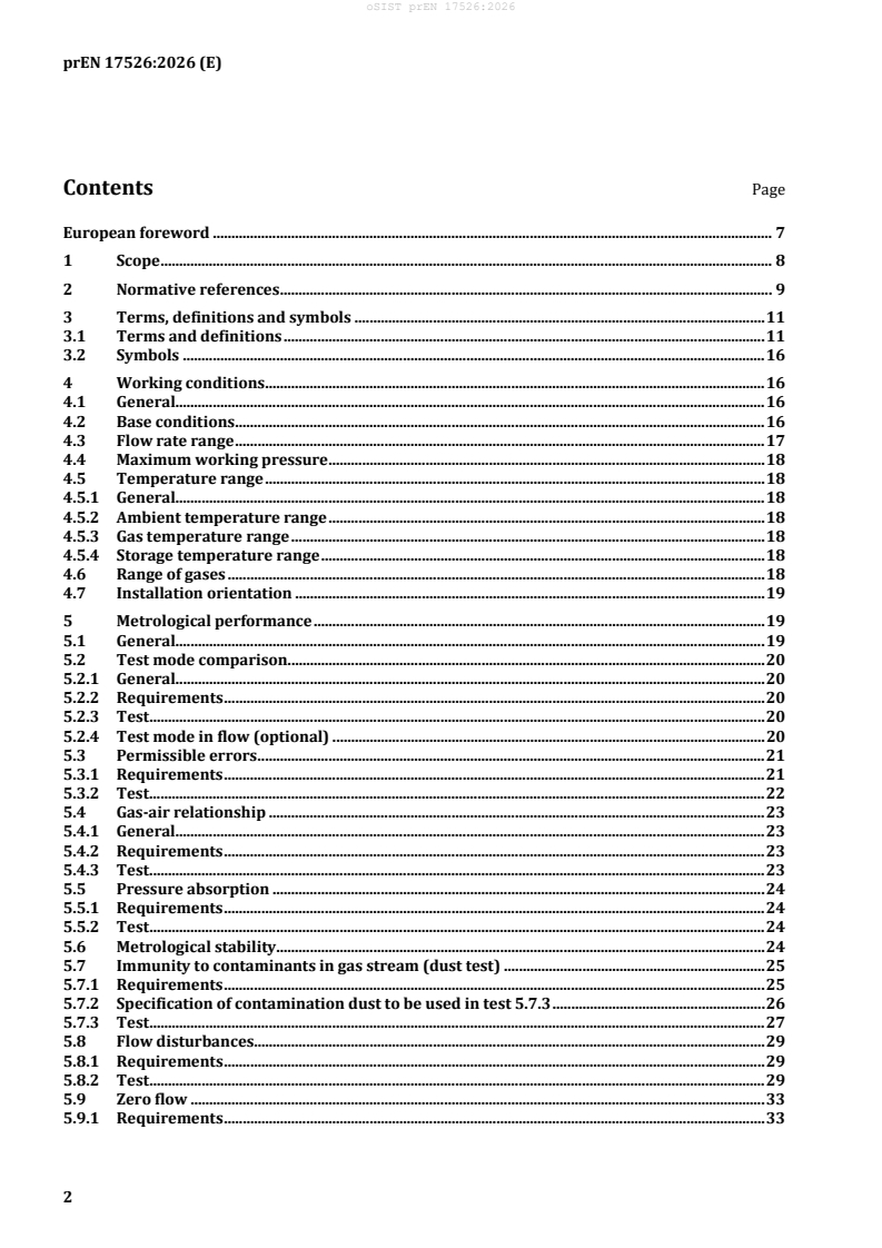
Contents Page
European foreword . 7
1 Scope . 8
2 Normative references . 9
3 Terms, definitions and symbols . 11
3.1 Terms and definitions . 11
3.2 Symbols . 16
4 Working conditions . 16
4.1 General. 16
4.2 Base conditions . 16
4.3 Flow rate range . 17
4.4 Maximum working pressure . 18
4.5 Temperature range . 18
4.5.1 General. 18
4.5.2 Ambient temperature range . 18
4.5.3 Gas temperature range . 18
4.5.4 Storage temperature range . 18
4.6 Range of gases . 18
4.7 Installation orientation . 19
5 Metrological performance . 19
5.1 General. 19
5.2 Test mode comparison. 20
5.2.1 General. 20
5.2.2 Requirements . 20
5.2.3 Test . 20
5.2.4 Test mode in flow (optional) . 20
5.3 Permissible errors . 21
5.3.1 Requirements . 21
5.3.2 Test . 22
5.4 Gas-air relationship . 23
5.4.1 General. 23
5.4.2 Requirements . 23
5.4.3 Test . 23
5.5 Pressure absorption . 24
5.5.1 Requirements . 24
5.5.2 Test . 24
5.6 Metrological stability . 24
5.7 Immunity to contaminants in gas stream (dust test) . 25
5.7.1 Requirements . 25
5.7.2 Specification of contamination dust to be used in test 5.7.3 . 26
5.7.3 Test . 27
5.8 Flow disturbances. 29
5.8.1 Requirements . 29
5.8.2 Test . 29
5.9 Zero flow . 33
5.9.1 Requirements . 33
5.9.2 Test . 33
5.10 Reverse flow . 34
5.10.1 Requirements . 34
5.10.2 Test . 34
5.11 Low flow registration (starting flow rate) . 34
5.11.1 Requirements . 34
5.11.2 Test . 34
5.12 Overload flow rate . 34
5.12.1 Requirements . 34
5.12.2 Test . 34
5.13 Pulsed (unsteady) flow . 35
5.13.1 General . 35
5.13.2 Requirements . 35
5.13.3 Test . 35
6 Construction and materials . 35
6.1 Mechanical interference . 35
6.1.1 Requirements . 35
6.1.2 Test . 36
6.2 Unauthorized interference. 36
6.2.1 Requirements . 36
6.2.2 Test . 36
6.3 Robustness of meter case . 36
6.3.1 Meter case . 36
6.3.2 Protection against penetration of dust and water . 37
6.3.3 External leak tightness . 37
6.3.4 Resistance to internal pressure . 37
6.3.5 Heat resistance . 38
6.3.6 Resistance to impact . 38
6.3.7 Resistance to mishandling. 41
6.4 Connections . 41
6.4.1 Orientation . 41
6.4.2 Threads and flanges for single and two pipe meters . 42
6.4.3 Strength . 45
6.5 Resistance to vibration . 46
6.5.1 Requirements . 46
6.5.2 Apparatus . 46
6.5.3 Test . 47
6.6 Corrosion protection . 48
6.6.1 General . 48
6.6.2 External corrosion. 48
6.7 Flame retardance of external surfaces . 49
6.7.1 Requirements . 49
6.7.2 Test . 49
6.8 Requirements for rubber components in the gas path . 50
6.8.1 Requirements . 50
6.8.2 Test . 50
6.9 Resistance to storage temperature range . 50
6.9.1 Requirements . 50
6.9.2 Test . 50
6.10 Resistance to toluene/iso-octane vapour . 50
6.10.1 Requirements . 50
6.10.2 Test . 50
6.11 Resistance to water vapour . 52
6.11.1 Requirements . 52
6.11.2 Test . 52
6.11.3 Example of a typical apparatus . 52
6.12 Ageing . 53
6.12.1 Requirements . 53
6.12.2 Test . 53
6.13 Hydrogen compatibility of materials . 54
7 Optional features . 54
7.1 Pressure measuring point . 54
7.1.1 Requirements . 54
7.1.2 Test . 54
7.2 Electrical insulating feet (optional) . 55
7.2.1 Requirements . 55
7.2.2 Test . 55
7.3 Resistance to high ambient temperatures . 55
7.3.1 Requirements . 55
7.3.2 Test . 56
7.3.3 Example of a typical resistance to high ambient temperature test apparatus . 56
7.4 Additional functionalities (if fitted) . 57
7.4.1 Requirements . 57
7.4.2 Test . 57
7.5 Use in hazardous zones . 58
7.5.1 Requirement . 58
7.5.2 Test . 58
8 Index . 58
8.1 Recording and storage . 58
8.1.1 Requirement . 58
8.1.2 Test . 58
8.2 Display . 58
8.2.1 Requirements . 58
8.2.2 Test . 59
8.3 Display functionality . 59
8.3.1 Requirements . 59
8.3.2 Test . 59
8.4 Non-volatile memory . 60
8.4.1 Requirements . 60
8.4.2 Test . 60
9 Marking . 61
9.1 All meters . 61
9.2 Two-pipe meters . 61
9.2.1 Requirements . 61
9.2.2 Test . 61
9.3 Durability and legibility of marking and labels . 62
9.3.1 Requirements . 62
9.3.2 Closed location Test . 62
9.3.3 Open location Tests . 62
9.4 Indelibility of marking . 63
9.4.1 Requirement . 63
9.4.2 Tests . 63
10 Software . 63
10.1 Requirements . 63
10.2 Test . 63
11 Communications . 64
11.1 General . 64
11.1.1 Requirements . 64
11.1.2 Test . 64
11.2 Metrological influence of radio communication function . 64
11.2.1 Requirements . 64
11.2.2 Test . 64
11.3 Test mode . 65
11.3.1 Requirements . 65
11.3.2 Test . 65
11.4 Data optical port (optional) . 65
11.5 Galvanic port (optional) . 65
11.6 Diagnostics . 65
11.6.1 Requirements . 65
11.6.2 Test . 66
11.6.3 Display flags . 66
12 Battery . 66
12.1 General . 66
12.2 Additional requirements . 67
12.2.1 Voltage interruptions . 67
12.2.2 Minimum operating voltage . 67
12.2.3 Battery life . 67
13 Immunity to electromagnetic disturbances . 67
13.1 General . 67
13.2 Electrostatic discharge . 67
13.2.1 Requirements . 67
13.2.2 Test . 67
13.3 Radio frequency electromagnetic field . 68
13.3.1 Requirements . 68
13.3.2 Test . 68
13.4 Electromagnetic induction (power frequency) . 68
13.4.1 Requirements . 68
13.4.2 Test . 69
13.5 Electromagnetic induction (pulsed field) . 69
13.5.1 Requirements . 69
13.5.2 Test . 69
13.6 Radio interference suppression . 69
13.6.1 Requirements . 69
13.6.2 Test . 69
14 Instructions . 69
15 Meters supplied for testing . 70
16 Production requirements . 73
Annex A (informative) Key physical property of gases for meter performance testing . 74
A.1 General . 74
A.2 Basic theory . 74
A.3 Selection criteria for test gases . 74
Annex B (normative) Gases for meter performance testing . 76
B.1 General. 76
nd
B.2 Test gases for 2 family gases . 76
rd
B.3 Test gases for 3 family gases . 77
B.4 Test gases for blended gases . 77
B.5 Test gases for hydrogen . 78
Annex C (informative) Meters without temperature or pressure conversion . 79
C.1 Scope . 79
C.2 Meters without temperature conversion . 79
C.3 Meters without pressure conversion . 79
Annex D (normative) Production requirements for gas meters . 80
D.1 Specification . 80
D.2 Technical requirements . 80
D.3 Certificates of conformity . 80
Annex E (normative) Meters designed for measuring blended gas and/or hydrogen . 82
E.1 General. 82
E.2 Flow Rate Range for hydrogen . 83
E.3 Hydrogen-air relationship . 84
E.4 Pressure absorption for hydrogen . 84
E.5 Low flow registration (starting flow rate) for hydrogen . 85
E.6 Compatibility of materials for use with hydrogen . 85
E.7 External leak tightness for hydrogen . 86
E.8 Use in hazardous zones . 86
E.9 Resolution of meter index for meters designed for hydrogen measurement . 86
E.10 Diagnostics . 87
Bibliography . 88
European foreword
This document (prEN 17526:2026) has been prepared by Technical Committee CEN/TC 237 “Gas
meters”, the secretariat of which is held by BSI.
This document is currently submitted to the CEN Enquiry.
This document will supersede EN 17526:2021+A1:2025.
EN 17526:2021+A1:2025:
— Scope modified to consider the introduction of Annex E;
— Errors limit in 5.3.2.3 Method b) corrected to 1,3 % as per 5.3.1 Method b);
— Table 9 and Table 13 modified to comply with 1/3 of MPE requirement;
— New test procedure step introduced in 5.7.3 in case the meter is fitted with an internal valve;
3 3
— Different test rig design in 5.7.3 for meters with Q = 2,5 m /h or Q = 4 m /h;
max max
— Typo correction in Table 16: average value is now 0,8 Q ;
min
— Introduced new subclause 6.13 with Hydrogen compatibility of materials;
— Typo correction in 9.3.2 with “deionized water” replacing “ionized water”;
— Table 23 modified removing two flags: “Nothing” and “O”;
— New test gases for blended gas and hydrogen added in Annex B;
— Introduced new Annex E (informative), Meters designed to measure blended gas and/or hydrogen;
— Removal of Annex ZA.
1 Scope
This document specifies requirements and tests for the construction, performance, safety and production
of battery powered class 1,5 Capillary Thermal-Mass Flow sensor gas meters (hereinafter referred to as
meter(s)). This applies to meters having co-axial single pipe, or two pipe connections, which are used to
nd rd
measure volumes of fuel gases of the 2 and/or 3 family, as given in EN 437:2021.
In general, the term “thermal mass flow meters” applies to a flow-measuring device using heat transfer
to measure and indicate gas flowrate, as defined in ISO 14511.
NOTE Although the word “mass” is present in the definition of the measurement principle, gas meters covered
by this document provide measurement of gas at base conditions of temperature and pressure.
These meters have a maximum working pressure not exceeding 0,5 bar and a maximum flowrate not
exceeding 160 m /h over a minimum ambient temperature range of −10 °C to +40 °C and a gas
temperature range as specified in the marking, with a minimum range of 40 °C.
For meters designed for hydrogen measurement, the maximum flowrate is not exceeding 480 m /h,
whilst the other characteristics are as stated above.
This document applies to meters indicating volume at base conditions, which are installed in locations
with vibration and shocks of low significance. It applies to meters in:
— closed locations (indoor or outdoor with protection, as specified in the instruction manual) with
condensing humidity or with non-condensing humidity;
or, if specified in the marking:
— open locations (outdoor without any covering) both with condensing humidity or with non-
condensing humidity;
and in locations with electromagnetic disturbances likely to be found in residential, commercial and light
industrial use. For meters which indicate unconverted volume, reference can be made to Annex C.
Unless otherwise stated, all pressures given in this document are gauge pressures.
Requirements for electronic indexes, valves and additional requirements for batteries incorporated in
the meter and any other additional functionalities are given in EN 16314:2013.
Unless otherwise stated in a particular test, the tests are carried out on meters that include additional
functionality devices, as indicated in the instruction manual.
Clauses 1 to 13 are for design and type testing only.
For meters designed for blended gas and/or hydrogen measurement, refer to Annex E.
This document refers only to hydrogen as specified in ISO 14687:2025 with a purity of type I grade A or
better.
nd rd
Unless otherwise stated, all tests applicable to 2 and 3 family gases are applicable also to blended gas
and hydrogen.
Mixtures with a hydrogen concentration above 20 % and below 98 % by volume are not covered by this
document.
2 Normative references
The following documents are referred to in the text in such a way that some or all of their content
constitutes requirements of this document. For dated references, only the edition cited applies. For
undated references, the latest edition of the referenced document (including any amendments) applies.
EN 437:2021, Test gases — Test pressures — Appliance categories
EN 549:2019+A2:2024, Rubber materials for seals and diaphragms for gas appliances and gas equipment
EN 1092-1:2018, Flanges and their joints — Circular flanges for pipes, valves, fittings and accessories, PN
designated — Part 1: Steel flanges
EN 16314:2013, Gas meters — Additional functionalities
EN ISO 228-1:2003, Pipe threads where pressure-tight joints are not made on the threads — Part 1:
Dimensions, t
...