


SIST EN 12516-2:2015/kFprA1:2021
(Amendment)Industrial valves - Shell design strength - Part 2: Calculation method for steel valve shells
Industrial valves - Shell design strength - Part 2: Calculation method for steel valve shells
This European Standard specifies the method for the strength calculation of the shell with respect to internal pressure of the valve.
Industriearmaturen - Gehäusefestigkeit - Teil 2: Berechnungsverfahren für drucktragende Gehäuse von Armaturen aus Stahl
Robinetterie industrielle - Résistance mécanique des enveloppes - Partie 2 : Méthode de calcul relative aux enveloppes d'appareils de robinetterie en acier
Industrijski ventili - Trdnost ohišja - 2. del: Metoda za izračun ohišij jeklenih ventilov - Dopolnilo A1
General Information
- Status
- Not Published
- Public Enquiry End Date
- 19-Dec-2019
- Technical Committee
- TLP - Pressure vessels
- Current Stage
- 98 - Abandoned project (Adopted Project)
- Start Date
- 24-Oct-2025
- Due Date
- 29-Oct-2025
- Completion Date
- 24-Oct-2025

Relations
- Consolidated By
SIST EN 12516-2:2015+A1:2021 - Industrial valves - Shell design strength - Part 2: Calculation method for steel valve shells - Effective Date
- 18-Aug-2021
- Effective Date
- 01-Dec-2019
Overview
SIST EN 12516-2:2015/kFprA1:2021 - Industrial valves – Shell design strength – Part 2: Calculation method for steel valve shells is a European standard developed by SIST that specifies a comprehensive methodology for calculating the strength of steel valve shells subjected to internal pressure. This standard is essential for ensuring the safe and reliable operation of industrial valves within pressurized systems, establishing consistent requirements for the design and verification of steel valve shells across various industries.
The standard aligns with the essential requirements of the EU Pressure Equipment Directive (2014/68/EU), providing a harmonized approach to compliance and reinforcing safety within pressure equipment manufacturing and operation.
Key Topics
- Calculation Methodology: Defines a step-by-step process for determining the required wall thickness and strength of steel valve shells under internal pressure.
- Material Requirements: Details the properties and minimum mechanical characteristics for various steel grades, including austenitic steel and cast steel, ensuring suitability for pressure applications.
- Allowable Stresses: Sets clear parameters for nominal design stresses based on material type, temperature, and testing conditions.
- Design for Pressure: Outlines the method to calculate the strength of shells, including particular consideration for geometric features such as flanges, branch connections, and intersection areas.
- Welding Factors: Provides calculation factors for welded joints depending on the weld type and testing regime, enhancing the design’s robustness.
- Compliance with European Legislation: Supports manufacturers and operators in meeting EU regulatory requirements for pressure equipment.
- Updated Reference Standards: Incorporates the latest references for related standards such as EN 19 (Marking of metallic valves) and EN 13445-3 (Unfired pressure vessels - Design).
Applications
This standard is widely applicable across sectors involving pressure-containing equipment. Typical applications include:
- Oil and Gas: Design and manufacture of steel valves used in pipelines, refineries, and upstream installations where high-pressure resistance and operational safety are critical.
- Chemical and Petrochemical: Specification and validation of valve shells for use in process industries, ensuring integrity in corrosive or hazardous environments.
- Power Generation: Calculation and verification of valve bodies in power plants, supporting pressure boundaries in steam and cooling systems.
- Water and Wastewater: Engineering of robust valves for municipal and industrial water treatment plants operating under varying pressures.
- General Industrial Use: Provides a foundation for any steel valve shell subjected to regulated pressure service, promoting best practices in mechanical design and risk management.
By following SIST EN 12516-2:2015/kFprA1:2021, organizations ensure not only technical adequacy but also regulatory compliance, product reliability, and end-user safety through precise calculation and design validation.
Related Standards
For comprehensive valve shell design and testing, the following related standards should also be considered:
- SIST EN 12516-1: Shell design strength - Part 1: Tabulation method for steel valve shells
- EN 19: Industrial valves - Marking of metallic valves
- EN 13445-3: Unfired pressure vessels - Design
- EN 12266-1 / EN 12266-2: Testing of metallic valves
- Directive 2014/68/EU: Pressure Equipment Directive (PED)
Utilizing these standards together supports a holistic and compliant approach to pressure equipment quality and safety management.
Keywords: industrial valves, valve shell calculation, steel valve shells, pressure equipment, design strength, European standard, shell thickness, allowable stresses, EU Directive 2014/68/EU, SIST standards, pressure vessel design
Get Certified
Connect with accredited certification bodies for this standard

Institut za varilstvo d.o.o. (Welding Institute)
Slovenia's leading welding institute since 1952. ISO 3834, EN 1090, pressure equipment certification, NDT personnel, welder qualification. Only IIW Au
Sponsored listings
Frequently Asked Questions
SIST EN 12516-2:2015/kFprA1:2021 is a draft published by the Slovenian Institute for Standardization (SIST). Its full title is "Industrial valves - Shell design strength - Part 2: Calculation method for steel valve shells". This standard covers: This European Standard specifies the method for the strength calculation of the shell with respect to internal pressure of the valve.
This European Standard specifies the method for the strength calculation of the shell with respect to internal pressure of the valve.
SIST EN 12516-2:2015/kFprA1:2021 is classified under the following ICS (International Classification for Standards) categories: 23.060.01 - Valves in general. The ICS classification helps identify the subject area and facilitates finding related standards.
SIST EN 12516-2:2015/kFprA1:2021 has the following relationships with other standards: It is inter standard links to SIST EN 12516-2:2015+A1:2021, SIST EN 12516-2:2015. Understanding these relationships helps ensure you are using the most current and applicable version of the standard.
SIST EN 12516-2:2015/kFprA1:2021 is associated with the following European legislation: EU Directives/Regulations: 2014/68/EU; Standardization Mandates: M/071. When a standard is cited in the Official Journal of the European Union, products manufactured in conformity with it benefit from a presumption of conformity with the essential requirements of the corresponding EU directive or regulation.
SIST EN 12516-2:2015/kFprA1:2021 is available in PDF format for immediate download after purchase. The document can be added to your cart and obtained through the secure checkout process. Digital delivery ensures instant access to the complete standard document.
Standards Content (Sample)
SLOVENSKI STANDARD
SIST EN 12516-2:2015/oprA1:2019
01-december-2019
Industrijski ventili - Trdnost ohišja - 2. del: Metoda za izračun ohišij jeklenih
ventilov - Dopolnilo A1
Industrial valves - Shell design strength - Part 2: Calculation method for steel valve shells
Industriearmaturen - Gehäusefestigkeit - Teil 2: Berechnungsverfahren für
drucktragende Gehäuse von Armaturen aus Stahl
Robinetterie industrielle - Résistance mécanique des enveloppes - Partie 2 : Méthode de
calcul relative aux enveloppes d'appareils de robinetterie en acier
Ta slovenski standard je istoveten z: EN 12516-2:2014/prA1:2019
ICS:
23.060.01 Ventili na splošno Valves in general
SIST EN 12516-2:2015/oprA1:2019 en,fr,de
2003-01.Slovenski inštitut za standardizacijo. Razmnoževanje celote ali delov tega standarda ni dovoljeno.
SIST EN 12516-2:2015/oprA1:2019
SIST EN 12516-2:2015/oprA1:2019
DRAFT
EUROPEAN STANDARD
EN 12516-2:2014
NORME EUROPÉENNE
EUROPÄISCHE NORM
prA1
October 2019
ICS 23.060.01
English Version
Industrial valves - Shell design strength - Part 2:
Calculation method for steel valve shells
Robinetterie industrielle - Résistance mécanique des Industriearmaturen - Gehäusefestigkeit - Teil 2:
enveloppes - Partie 2 : Méthode de calcul relative aux Berechnungsverfahren für drucktragende Gehäuse von
enveloppes d'appareils de robinetterie en acier Armaturen aus Stahl
This draft amendment is submitted to CEN members for enquiry. It has been drawn up by the Technical Committee CEN/TC 69.
This draft amendment A1, if approved, will modify the European Standard EN 12516-2:2014. If this draft becomes an
amendment, CEN members are bound to comply with the CEN/CENELEC Internal Regulations which stipulate the conditions for
inclusion of this amendment into the relevant national standard without any alteration.
This draft amendment was established by CEN in three official versions (English, French, German). A version in any other
language made by translation under the responsibility of a CEN member into its own language and notified to the CEN-CENELEC
Management Centre has the same status as the official versions.
CEN members are the national standards bodies of Austria, Belgium, Bulgaria, Croatia, Cyprus, Czech Republic, Denmark, Estonia,
Finland, France, Germany, Greece, Hungary, Iceland, Ireland, Italy, Latvia, Lithuania, Luxembourg, Malta, Netherlands, Norway,
Poland, Portugal, Republic of North Macedonia, Romania, Serbia, Slovakia, Slovenia, Spain, Sweden, Switzerland, Turkey and
United Kingdom.
Recipients of this draft are invited to submit, with their comments, notification of any relevant patent rights of which they are
aware and to provide supporting documentation.
Warning : This document is not a European Standard. It is distributed for review and comments. It is subject to change without
notice and shall not be referred to as a European Standard.
EUROPEAN COMMITTEE FOR STANDARDIZATION
COMITÉ EUROPÉEN DE NORMALISATION
EUROPÄISCHES KOMITEE FÜR NORMUNG
CEN-CENELEC Management Centre: Rue de la Science 23, B-1040 Brussels
© 2019 CEN All rights of exploitation in any form and by any means reserved Ref. No. EN 12516-2:2014/prA1:2019:2019 E
worldwide for CEN national Members.
SIST EN 12516-2:2015/oprA1:2019
EN 12516-2:2014/prA1:2019 (E)
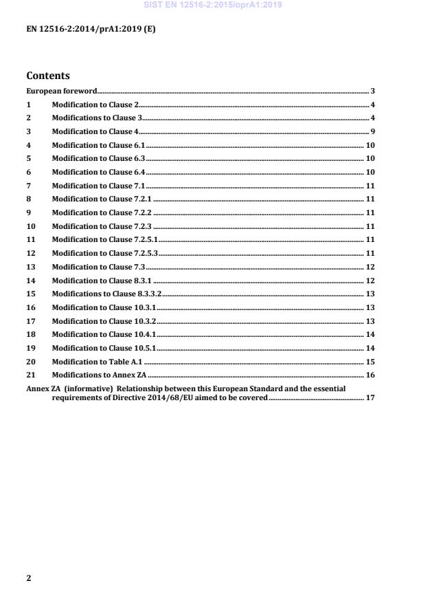
Contents
European foreword . 3
1 Modification to Clause 2. 4
2 Modifications to Clause 3. 4
3 Modification to Clause 4. 9
4 Modification to Clause 6.1 . 10
5 Modification to Clause 6.3 . 10
6 Modification to Clause 6.4 . 10
7 Modification to Clause 7.1 . 11
8 Modification to Clause 7.2.1 . 11
9 Modification to Clause 7.2.2 . 11
10 Modification to Clause 7.2.3 . 11
11 Modification to Clause 7.2.5.1 . 11
12 Modification to Clause 7.2.5.3 . 11
13 Modification to Clause 7.3 . 12
14 Modification to Clause 8.3.1 . 12
15 Modifications to Clause 8.3.3.2 . 13
16 Modification to Clause 10.3.1 . 13
17 Modification to Clause 10.3.2 . 13
18 Modification to Clause 10.4.1 . 14
19 Modification to Clause 10.5.1 . 14
20 Modification to Table A.1 . 15
21 Modifications to Annex ZA . 16
Annex ZA (informative) Relationship between this European Standard and the essential
requirements of Directive 2014/68/EU aimed to be covered . 17
SIST EN 12516-2:2015/oprA1:2019
EN 12516-2:2014/prA1:2019 (E)
European foreword
This document (EN 12516-2:2014/prA1:2019) has been prepared by Technical Committee CEN/TC 69
“Industrial valves”, the secretariat of which is held by AFNOR.
This document is currently submitted to the CEN Enquiry.
This document has been prepared under a standardization request given to CEN by the European
Commission and the European Free Trade Association, and supports essential requirements of EU
Directive 2014/68/EU.
For relationship with EU Directive 2014/68/EU, see informative Annex ZA which is an integral part of
this document.
SIST EN 12516-2:2015/oprA1:2019
EN 12516-2:2014/prA1:2019 (E)
1 Modification to Clause 2
Replace “EN 19:2002, Industrial valves — Marking of metallic valves” by “EN 19:2016, Industrial
valves — Marking of metallic valves”
Replace “EN 13445-3:2014, Unfired pressure vessels — Part 3: Design” by “EN 13445-3:2014/A3:2017,
Unfired pressure vessels — Part 3: Design”
2 Modifications to Clause 3
Replace Table 1 by the following.
“
Table 1 — Symbols characteristics and units
Symbol Unit Characteristic
a
mm lever arm for horizontal force
H
a
mm lever arm for bolt force
S
a
mm lever arm for vertical force
V
B — calculation coefficient to determine the thickness of the flange
B
— calculation coefficient for oval and rectangular cross-sections
1…3
B
— correction factor for oval flanges
B , B
— calculation coefficient for flat circular plates
FI FII
B
— calculation coefficient to determine the thickness of the flange
h
B , B
— calculation coefficient for flat circular plates
MI MII
B , B
— calculation coefficient for flat circular plates
PI PII
b mm double flange width
b
mm minor width in oval and rectangular cross section
b
mm major width in oval and rectangular cross section
b , b
mm width of the seal
D1 D2
b’
mm width in oval and rectangular cross section
b
mm width of the seal
D
b
mm effective width for reinforcement
s
C ,C ,C
— calculation coefficient for covers made of flat plates
x y z
C –– calculation coefficient for lens-shaped gaskets
c mm design allowance for bolts
c
mm fabrication tolerance
c
mm standardized corrosion and erosion allowance
d
mm outside diameter
o
SIST EN 12516-2:2015/oprA1:2019
EN 12516-2:2014/prA1:2019 (E)
Symbol Unit Characteristic
d , d'
mm diameter in base body
0 0
d , d mm diameter for self-sealing closure
01 02
d
mm diameter in branch
d
mm diameter in further branch
d
mm outside diameter of collar flange
d
mm outside diameter of the plate/cover
A
d
mm outside flange diameter
a
d
mm inside diameter
i
d
mm diameter of the biggest inscribed circle
f
d
mm diameter in knuckle
k
d
mm diameter in corner welds
K
d
mm hole diameter
L
d'
mm reduced bolt hole diameter
L
d
mm mean diameter of the plate/cover
m
d
mm mean diameter of the face (see Figure 28)
mA
d'
mm mean diameter
m
d
mm mean diameter of the seal
D
d
mm required bolt diameter
s
d
mm bold circle diameter/reference circle diameter
t
d
mm diameter of centre of gravity
p
d
mm stuffing box outside diameter
ast
d
mm stuffing box inside diameter
ist
d
mm calculated bolt diameter without design allowance
S0
d
mm diameter of the vertical force at the cone
V
E MPa modulus of elasticity
E
MPa modulus of elasticity for material of the seal
D
e
mm wall thickness
n
e
mm wall thickness (final/actual)
an
e actual wall thickness less c and c
mm
acn 1 2
e
mm thickness of flange neck
acF
e calculated theoretical minimum wall thickness, without c and c
mm
cn 1 2
F
N minimum bolt force for the assembly condition
DV
SIST EN 12516-2:2015/oprA1:2019
EN 12516-2:2014/prA1:2019 (E)
Symbol Unit Characteristic
F
N flange force
F
F
N horizontal component force
H
F
N bolt force for operating conditions
S
F
N minimum bolt force
SB
F
N bolt force for assembly conditions
S0
F
N tensile force
T
F
N vertical force at the cone
V
F
N additional force
Z
f MPa nominal design stress
maximum value of the nominal design stress for normal operating load
f
MPa
d
cases
f
MPa nominal design stress for design conditions at temperature t °C
d/t
g , g
mm welding throat depth
1 2
h mm plate thickness
h
mm minimum height for the seating shoulder
h
mm minimum height of the inserted ring
h
mm minimum depth of the sealing ledge
D
h
mm plate thickness
r
h
mm height of flange hub
A
h
mm plate thickness
c
h
mm thickness of flange
F
h
mm reduced plate thickness
N
k
— welding factor
c
l mm length
l
mm effective length for cylindrical bodies
0…3
l' mm length which is influenced by the entry nozzle
l’
mm length for calculating body shapes in cross section II
∩l3 mm length for calculating body shapes in cross section II
M Nm external moment
M summary of moments M , M , M
Nm
i P F M
M
Nm external moment
a
M
Nm moment for assembly condition
a0
M
Nm moment for operation condition
aB
SIST EN 12516-2:2015/oprA1:2019
EN 12516-2:2014/prA1:2019 (E)
Symbol Unit Characteristic
M
Nm single force (point force)
F
M
Nm maximum bending moment
max
M
Nm rim moment
M
M
Nm resulting moment from internal pressure
P
M
Nm bending moment in radial direction
r
M
Nm bending moment in tangential direction
t
m –– gasket coefficient
n –– number of bolts
n
–– load carrying factor
p MPa pressure
p
MPa calculation pressure
c
p
MPa design pressure
d
p
MPa contact pressure
F
PS MPa maximum allowable pressure
R mm radius for calculating load cases
R
MPa upper yield strength
eH
R
MPa upper yield strength at temperature t °C
eH/t
R
mm inner Radius of spherical cap
i
R
MPa tensile strength
m
R
MPa tensile strength at temperature t °C
m/t
R
MPa creep rupture strength for T hours at temperature t °C
m/T/t
R
MPa 0,2 % - proof strength
p0,2
R
MPa 0,2 % - proof strength at temperature t °C
p0,2/t
R
MPa 0,2 % - proof strength at test temperature t °C
p0,2/t Test
R
MPa 1,0 % - proof strength at test temperature t °C
p1,0/t Test
R
MPa
...