


oSIST prEN IEC 60695-8-2:2026
(Main)Fire hazard testing - Part 8-2: Heat release - Summary and relevance of test methods
General Information
- Abstract
- Status
- Not Published
- Public Enquiry End Date
- 30-Sep-2026
- Technical Committee
- I09 - Imaginarni 09
- Current Stage
- 4020 - Public enquire (PE) (Adopted Project)
- Start Date
- 04-Aug-2026
- Due Date
- 22-Dec-2026

Overview
oSIST prEN IEC 60695-8-2:2026, developed by the Slovenski inštitut za standardizacijo (SIST), is part of the internationally recognized IEC 60695 series addressing fire hazard testing. This particular part (8-2) provides a comprehensive summary and evaluation of various test methods for determining heat release during fire tests, with a particular focus on their relevance for electrotechnical products and materials used within the electrical and electronic sectors.
Heat release is a crucial metric in assessing fire hazards, as the amount of energy released directly impacts fire growth, propagation, and the safety performance of materials. Understanding these test methods helps manufacturers, engineers, and safety professionals ensure that products meet safety and regulatory requirements, ultimately contributing to reduced fire risk and improved protection of life and property.
Key Topics
Summary of Heat Release Test Methods: The standard outlines a range of laboratory fire testing methods used to quantify heat released by materials under fire conditions, providing practical insights on their application and relevance.
Measurement Techniques:
- Complete Combustion: Use of oxygen bomb calorimeter (ISO 1716) for determining the total heat of combustion.
- Incomplete Combustion: Methods such as cone calorimeter (ISO 5660-1, ASTM E 1354), microscale calorimetry (ASTM D 7309), Ohio State University calorimeter (ASTM E 906), and fire propagation apparatus (ISO 12136).
Cable Fire Testing: Vertical and horizontal cable ladder tests are considered, showing specific approaches for assessing fire behavior of cables, which are critical components in many installations.
Test Data Relevance: The document evaluates how closely laboratory data reflect real-world fire scenarios and discusses the limitations and applicability of each test in fire risk assessment and fire safety engineering.
International Context: The standard references widely-adopted methods and aligns terminology with ISO 13943 to ensure consistency and rigor.
Applications
Implementing oSIST prEN IEC 60695-8-2:2026 delivers practical value across multiple sectors:
Product Development and Compliance: Manufacturers of electrotechnical equipment (such as consumer electronics, cables, enclosures) use these fire hazard test methods to meet international safety standards, regulatory requirements, and product certifications.
Fire Safety Engineering: Fire safety professionals and risk assessors rely on heat release data from standardized tests to design safer products and systems, perform fire modeling, and identify materials that minimize fire spread, toxic effluent release, and smoke generation.
Research and Material Selection: Material scientists leverage comparative data on heat release rates and combustion characteristics to select or develop materials with optimal fire performance for specific applications.
Regulatory and Market Access: The standard supports compliance with building codes (e.g., EN 13501 for construction products), marine safety regulations (SOLAS), and sector-specific directives, facilitating both national and international market access.
Related Standards
Organizations and professionals applying oSIST prEN IEC 60695-8-2:2026 will benefit from familiarity with the following related standards:
- IEC 60695-8-1: Fire hazard testing - Part 8-1: Heat release - General guidance
- IEC 60695-4: Fire hazard testing - Part 4: Terminology concerning fire tests for electrotechnical products
- ISO 13943: Fire safety - Vocabulary
- ISO 1716: Reaction to fire tests for products - Determination of the gross heat of combustion (calorific value)
- ISO 5660-1 / ASTM E 1354: Cone calorimeter test methods
- ASTM D 7309: Microscale combustion calorimetry
- ASTM E 906: Ohio State University calorimeter
- ISO 12136 / ASTM E 2058: Fire propagation apparatus for material flammability
By utilizing oSIST prEN IEC 60695-8-2:2026 aligned with these related standards, stakeholders can achieve thorough, internationally recognized fire hazard assessments for safer, more reliable electrotechnical products.
Relations
- Effective Date
- 10-Feb-2026
Get Certified
Connect with accredited certification bodies for this standard

IMQ S.p.A. (Certification)
Italian electrical product certification.

SLG Prüf- und Zertifizierungs GmbH
German testing and certification body.

UL Solutions
Global safety science company with testing, inspection and certification.
Sponsored listings
Frequently Asked Questions
oSIST prEN IEC 60695-8-2:2026 is a draft published by the Slovenian Institute for Standardization (SIST). Its full title is "Fire hazard testing - Part 8-2: Heat release - Summary and relevance of test methods". This standard covers: Fire hazard testing - Part 8-2: Heat release - Summary and relevance of test methods
Fire hazard testing - Part 8-2: Heat release - Summary and relevance of test methods
oSIST prEN IEC 60695-8-2:2026 is classified under the following ICS (International Classification for Standards) categories: 13.220.40 - Ignitability and burning behaviour of materials and products; 29.020 - Electrical engineering in general. The ICS classification helps identify the subject area and facilitates finding related standards.
oSIST prEN IEC 60695-8-2:2026 has the following relationships with other standards: It is inter standard links to SIST EN 60695-8-2:2017. Understanding these relationships helps ensure you are using the most current and applicable version of the standard.
oSIST prEN IEC 60695-8-2:2026 is available in PDF format for immediate download after purchase. The document can be added to your cart and obtained through the secure checkout process. Digital delivery ensures instant access to the complete standard document.
Standards Content (Sample)
SLOVENSKI STANDARD
01-september-2026
Preskušanje požarne ogroženosti - 8-2. del: Oddajanje toplote - Pregled in
primernost preskusnih metod
Fire hazard testing - Part 8-2: Heat release - Summary and relevance of test methods
Prüfungen zur Beurteilung der Brandgefahr - Teil 8-2: Wärmefreisetzung -
Zusammenfassung und Anwendbarkeit von Prüfverfahren
Essais relatifs aux risques du feu - Partie 8-2: Dégagement de chaleur - Résumé et
pertinence des méthodes d'essais
Ta slovenski standard je istoveten z: prEN IEC 60695-8-2:2026
ICS:
13.220.40 Sposobnost vžiga in Ignitability and burning
obnašanje materialov in behaviour of materials and
proizvodov pri gorenju products
29.020 Elektrotehnika na splošno Electrical engineering in
general
2003-01.Slovenski inštitut za standardizacijo. Razmnoževanje celote ali delov tega standarda ni dovoljeno.
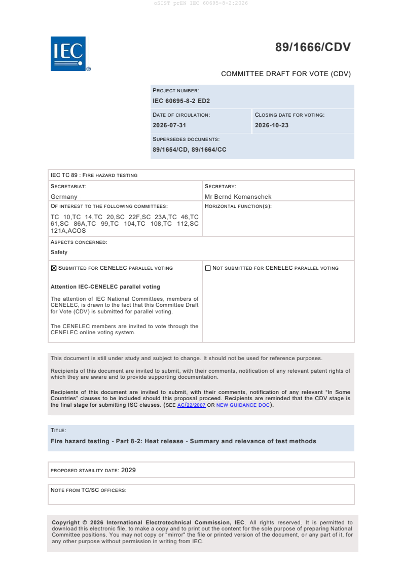
89/1666/CDV
COMMITTEE DRAFT FOR VOTE (CDV)
PROJECT NUMBER:
IEC 60695-8-2 ED2
DATE OF CIRCULATION: CLOSING DATE FOR VOTING:
2026-07-31 2026-10-23
SUPERSEDES DOCUMENTS:
89/1654/CD, 89/1664/CC
IEC TC 89 : FIRE HAZARD TESTING
SECRETARIAT: SECRETARY:
Germany Mr Bernd Komanschek
OF INTEREST TO THE FOLLOWING COMMITTEES: HORIZONTAL FUNCTION(S):
TC 10,TC 14,TC 20,SC 22F,SC 23A,TC 46,TC
61,SC 86A,TC 99,TC 104,TC 108,TC 112,SC
121A,ACOS
ASPECTS CONCERNED:
Safety
SUBMITTED FOR CENELEC PARALLEL VOTING NOT SUBMITTED FOR CENELEC PARALLEL VOTING
Attention IEC-CENELEC parallel voting
The attention of IEC National Committees, members of
CENELEC, is drawn to the fact that this Committee Draft
for Vote (CDV) is submitted for parallel voting.
The CENELEC members are invited to vote through the
CENELEC online voting system.
This document is still under study and subject to change. It should not be used for reference purposes.
Recipients of this document are invited to submit, with their comments, notification of any relevant patent rights of
which they are aware and to provide supporting documentation.
Recipients of this document are invited to submit, with their comments, notification of any relevant “In Some
Countries” clauses to be included should this proposal proceed. Recipients are reminded that the CDV stage is
the final stage for submitting ISC clauses. (SEE AC/22/2007 OR NEW GUIDANCE DOC).
TITLE:
Fire hazard testing - Part 8-2: Heat release - Summary and relevance of test methods
PROPOSED STABILITY DATE: 2029
NOTE FROM TC/SC OFFICERS:
download this electronic file, to make a copy and to print out the content for the sole purpose of preparing National
Committee positions. You may not copy or "mirror" the file or printed version of the document, o r any part of it, for
any other purpose without permission in writing from IEC.
IEC CDV 60695-8-2 © IEC 2026
Link to Committee Draft for Vote (CDV) online document:
Click here
How to access
This link leads you to the Online Standards Development (OSD) platform for National Mirror
Committee’s (NMC) comments. The project draft may be found further down this document.
Resource materials
We recommend NCs to review the available materials to better understand the member
commenting on the OSD platform. This includes the:
• OSD NC roles overview
• How to add and submit comments to the IEC
Contact
Should you require any assistance, please contact the IEC IT Helpdesk.
IEC CDV 60695-8-2 © IEC 2026
CONTENTS
CONTENTS . 3
FOREWORD . 5
INTRODUCTION . 7
1 Scope . 9
2 Normative references . 9
3 Terms and definitions . 9
4 Summary of test methods . 9
4.1 General . 9
4.2 Measurement of complete combustion . 10
4.2.1 The bomb calorimeter . 10
4.2.2 Purpose and principle . 10
4.2.3 Test specimen . 10
4.2.4 Test procedure . 10
4.2.5 Repeatability and reproducibility . 11
4.2.6 Relevance of test data . 11
4.3 Measurements of incomplete combustion . 11
4.3.1 Cone calorimeter . 11
4.3.2 Microscale calorimetry . 12
4.3.3 The Ohio State University calorimeter . 13
4.3.4 Fire propagation apparatus . 14
4.3.5 Single Burning Item (SBI) test. 15
4.4 Vertical cable ladder tests . 16
4.4.1 General . 16
4.4.2 ASTM and UL test methods . 16
4.4.3 EN test method . 17
4.5 Horizontal cable ladder test . 19
4.5.1 Test method . 19
4.5.2 Purpose and principle . 19
4.5.3 Test chamber . 19
4.5.4 Cable tray ladder . 19
4.5.5 Test specimens . 20
4.5.6 Test procedure . 20
4.5.7 Repeatability and reproducibility . 20
4.5.8 Relevance of test data . 20
4.6 Open calorimetry fire tests . 20
4.6.1 Test method . 20
4.6.2 Purpose and principle . 20
4.6.3 Test facility . 20
4.6.4 Specimen . 21
4.6.5 Test procedures. 21
4.6.6 Applicability . 21
5 Overview of test methods . 21
Bibliography . 23
Table 1 – Summary and comparison of vertical cable ladder tests . 18
Table 2 – Overview of heat release test methods . 21
IEC CDV 60695-8-2 © IEC 2026
IEC CDV 60695-8-2 © IEC 2026
INTERNATIONAL ELECTROTECHNICAL COMMISSION
____________
Fire hazard testing -
Part 8-2: Heat release - Summary and relevance of test methods
FOREWORD
1) The International Electrotechnical Commission (IEC) is a worldwide organization for
standardization comprising all national electrotechnical committees (IEC National Committees).
The object of IEC is to promote international co-operation on all questions concerning
standardization in the electrical and electronic fields. To this end and in addition to other
activities, IEC publishes International Standards, Technical Specifications, Technical Reports,
Publicly Available Specifications (PAS) and Guides (hereafter referred to as "IEC
Publication(s)"). Their preparation is entrusted to technical committees; any IEC National
Committee interested in the subject dealt with may participate in this preparatory work.
International, governmental and non-governmental organizations liaising with the IEC also
participate in this preparation. IEC collaborates closely with the International Organization for
Standardization (ISO) in accordance with conditions determined by agreement between the two
organizations.
2) The formal decisions or agreements of IEC on technical matters express, as nearly as
possible, an international consensus of opinion on the relevant subjects since each technical
committee has representation from all interested IEC National Committees.
3) IEC Publications have the form of recommendations for international use and are accepted
by IEC National Committees in that sense. While all reasonable efforts are made to ensure that
the technical content of IEC Publications is accurate, IEC cannot be held responsible for the
way in which they are used or for any misinterpretation by any end user.
4) In order to promote international uniformity, IEC National Committees undertake to apply IEC
Publications transparently to the maximum extent possible in their national and regional
publications. Any divergence between any IEC Publication and the corres ponding national or
regional publication shall be clearly indicated in the latter.
5) IEC itself does not provide any attestation of conformity. Independent certification bodies
provide conformity assessment services and, in some areas, access to IEC marks of conformity.
IEC is not responsible for any services carried out by independent certification bodies.
6) All users should ensure that they have the latest edition of this publication.
7) No liability shall attach to IEC or its directors, employees, servants or agents including
individual experts and members of its technical committees and IEC National Committees for
any personal injury, property damage or other damage of any nature whatsoever, whether direct
or indirect, or for costs (including legal fees) and expenses arising out of the publication, use
of, or reliance upon, this IEC Publication or any other IEC Publications.
8) Attention is drawn to the Normative references cited in this publication. Use of the referenced
publications is indispensable for the correct application of this publication.
9) IEC draws attention to the possibility that the implementation of this document may involve
the use of (a) patent(s). IEC takes no position concerning the evidence, validity or applicability
of any claimed patent rights in respect thereof. As of the date of publication of this document,
IEC [had/had not] received notice of (a) patent(s), which may be required to implement this
document. However, implementers are cautioned that this may not represent the latest
IEC CDV 60695-8-2 © IEC 2026
information, which may be obtained from the patent database available at https://patents.iec.ch.
IEC shall not be held responsible for identifying any or all such patent rights.
IEC 60695-8-2 has been prepared by IEC technical committee 89: Fire hazard testing. It is an
International Standard.
This second edition cancels and replaces the first edition published in 2016.
This edition includes the following significant technical changes with respect to the previous
edition:
a) the status of referenced standards was reviewed and updated.
b) Terms and definitions defined in ISO 13943-2017 are used.
c) Description of method of measurement of heat release were reviewed and updated.
d) Paragraphs for cable fire test methods are introcuded.
e) Pragraph for open calorimetry is added as 4.6.
The text of this International Standard is based on the following documents:
FDIS Report on voting
89/XXX/FDIS 89/XXX/RVD
Full information on the voting for the approval of this International Standard can be found in the
report on voting indicated in the above table.
The language used for the development of this International Standard is English.
This document was drafted in accordance with ISO/IEC Directives, Part 2, and developed in
accordance with ISO/IEC Directives, Part 1 and ISO/IEC Directives, IEC Supplement, available
at www.iec.ch/members_experts/refdocs. The main document types developed by IEC are
described in greater detail at www.iec.ch/publications.
A list of all the parts in the IEC 60695 series, under the general title Fire hazard testing, can be
found on the IEC website.
This International Standard is to be used in conjunction with IEC 60695-8-1.
IEC 60695-8 consists of the following parts:
– IEC 60695-8-1: Heat release – General guidance
– IEC 60695-8-2: Heat release – Summary and relevance of test methods
This document is to be used in conjunction with IEC 60695-8-1.
The committee has decided that the contents of this document will remain unchanged until the
stability date indicated on the IEC website under webstore.iec.ch in the data related to the
specific document. At this date, the document will be
– reconfirmed,
– withdrawn, or
– revised.
IEC CDV 60695-8-2 © IEC 2026
INTRODUCTION
In the design of an electrotechnical product, the risk of fire and the potential hazards associated
with fire need to be considered. In this respect the objective of component, circuit and
equipment design, as well as the choice of materials, is to reduce the risk of fire to a tolerable
level even in the event of reasonably foreseeable (mis)use, malfunction or failure. IEC 60695-
1-10:2016 [1], IEC 60695-1-11:2014 [2] and EN IEC 60695-1-12:2020 [3] provide guidance on
how this is to be accomplished.
Fires involving electrotechnical products can be originated from interal sources and also from
external non-electrical sources. These aspects are addressed within the overall fire hazard
assessment.
The aim of the IEC 60695 series of standards is to save lives and property by reducing the
number of fires or reducing the consequences of the fire. This can be accomplished by:
– trying to prevent ignition caused by an electrically energised component part and, in the
event of ignition, to confine any resulting fire within the bounds of the enclosure of the
electrotechnical product;
– trying to minimise flame spread beyond the product’s enclosure and to minimise the harmful
effects of fire effluents including heat, smoke, and toxic or corrosive combustion products.
Fires are responsible for creating hazards to life and property as a result of the generation of
heat (thermal hazard), toxic and/or corrosive compounds and obscuration of vision due to
smoke. The severity of a fire increases as the heat released increases, possibly leading to a
flashover fire.
One of the most important measurements in fire testing is the measurement of heat release and
it is used as an important factor in the determination of fire hazard. It is also used as one of the
parameters in fire safety engineering calculations.
The measurement and application of heat release data, together with other fire test data, can
be used to reduce the likelihood of or the effects of fire, even in the event of foreseeable
abnormal use, malfunction or failure of electrotechnical products.
When a material is heated by some external source, fire effluent can be generated and form a
mixture with air that can ignite and initiate a fire. The heat released in the process is carried
away by the mixture, radiation and transferred back to the solid material, promoting further
pyrolysis and sustaining the proces.
Heat can also be transferred to other nearby products, which can consequently igite, burn, and
generate additional heat and fire effluent.
The rate at which thermal energy is released during a fire is defined as the heat release rate.
Heat release rate is important because of its influence on flame spread and on the initiation of
secondary fires. Other characteristics are also important, such as ignitability, flame spread and
influence of fire effluents of the fire (see the IEC 60695 series of standards).
In addition to the summary of the test methods for measurment of heat release, described in
this document, following documents provides tehcnical background on the heat release
measurements:
Tewarson, A. and Khan, M.M., Fire Propagation Behavior of Electrical Cables, 2nd International
Symposium on Fire Safety Science, Hemisphere Publishing Corp., New York, NY, 1988 [4]
Tewarson, A. and Khan, M.M., Flame Propagation for Polymers in Cylindrical Configuration and
Vertical Orientation, 22nd International Symposium on Combustion, The Combustion Institute,
Pittsburgh, PA, 1988[5]
IEC CDV 60695-8-2 © IEC 2026
Tewarson, A. and Khan, M.M., A New Standard Test Method for Fire Propagation Behavior of
Electrical Cables in Industrial and Commercial Occupancies, Proceedings of the 5th
International Fire Conference, Interflam, 1990[6]
Tewarson, A. and Khan, M.M., A New Standard Test Method for the Quantification of Fire
Propagation Behavior of Electrical Cables Using Factory Mutual Research Corporation’s Small -
Scale Flammability Apparatus, Fire Technology, August 1992[7]
Khan, M.M., Bill, R.G. and Alpert, R.L., Screening of plenum cables using a small-scale fire test
protocol, Fire and Materials, 30, pp 65-76 (2006)[8]
Boardman, D., Khan, M.M., The Effectiveness of Coatings on the Flame Spread Behavior of
Electric Cables, Fire and Materials Conference 2013, January 2013[9]
IEC CDV 60695-8-2 © IEC 2026
1 Scope
This part of IEC 60695 provides a summary of published test methods that are relevant to the
determination of the heat released during fire tests from electrotechnical products or materials
from which they are formed. It represents the current state of the art of the test methods and
includes special observations on their relevance and use.
The list of test methods is not to be considered exhaustive, and test methods that were not
developed by the IEC are not to be considered as endorsed by the IEC unless this is specifically
stated.
Heat release data can be used as part of fire hazard assessment and in fire safety engineering,
as described in IEC 60695-1-10[1], IEC 60695-1-11[2] and IEC 60695-1-12[3].
2 Normative references
The following documents are referred to in the text in such a way that some or all of their content
constitutes requirements of this document. For dated references, only the edition cited applies.
For undated references, the latest edition of the referenced document (including any
amendments) applies.
IEC GUIDE 104:2019, The preparation of safety publications and the use of basic safety
publications and group safety publications
IEC 60695-4:2021, Fire hazard testing - Part 4: Terminology concerning fire tests for
electrotechnical products
IEC 60695-8-1:2016, Fire hazard testing - Part 8-1: Heat release - General guidance
ISO 13943:2023, Fire safety — Vocabulary
3 Terms and definitions
For the purposes of this document, the terms and definitions given in IEC 60695-4:2021 and
ISO 13943:2023 ISO 13943:2017 apply.
ISO and IEC maintain terminology databases for use in standardization at the following
addresses:
– IEC Electropedia: available at https://www.electropedia.org/
– ISO Online browsing platform: available at https://www.iso.org/obp
4 Summary of test methods
4.1 General
This summary does not replace published standards, which are the only valid reference
documents.
In cases where fire tests are not yet specified, and need to be developed or altered for the
special purpose of an IEC technical committee, this shall be done in liaison with the relevant
IEC technical committee, as mandated by IEC GUIDE 104:2019 . The tes t method(s) selected
shall be relevant to the fire scenario of concern.
IEC CDV 60695-8-2 © IEC 2026
General guidance on heat release tests for electrotechnical products is given in IEC 60695 -8-
1:2016.
4.2 Measurement of complete combustion
4.2.1 The bomb calorimeter
The oxygen bomb calorimeter is described in ISO 1716 [10].
4.2.2 Purpose and principle
The purpose of the method is to measure the gross heat of combustion at constant volume. A
test specimen of specified mass is burned under standardized conditions, in a constant volume,
in an atmosphere of oxygen, in a sealed calorimeter calibrated by combustion of certified
benzoic acid. The heat of combustion determined under these conditions is calculated on the
basis of the observed temperature rise, taking into account heat loss and the latent heat of
vaporization of water.
4.2.3 Test specimen
The test specimen is typically a mixture of 0,5 g of finely powdered benzoic acid and, also in a
finely divided state, 0,5 g of the material under test.
4.2.4 Test procedure
The "bomb" is a central vessel that is sufficiently strong to withstand high pressures so that its
internal volume remains constant. The bomb is immersed in a stirred water bath, and the
combination of bomb and water bath is the calorimeter. The calorimeter is also immersed in an
outer water bath. During a combustion reaction, the temperature of the water in the calorimeter
and in the outer water bath is continuously monitored and adjusted by electrical heating to the
same value. This is to ensure that there is no net loss of heat from the calorimeter to its
surroundings, i.e. to ensure that the calorimeter is adiabatic.
To carry out a measurement, a test specimen, consisting of a known mass of benzoic acid
mixed with a known mass of test material, is placed in a crucible inside the bomb in contact
with an electrical ignition wire. The vessel is filled with oxygen under pr essure (3,0 MPa to 3,5
MPa), sealed and allowed to attain thermal equilibrium. The sample is then ignited using a
measured input of energy. Combustion is complete because it takes place in an excess of high
pressure oxygen. The heat released is calculated from the known heat capacity of the
calorimeter and the rise of temperature that occurs as a result of the combustion reaction.
The experiment gives the heat released at constant volume, i.e. the change in internal energy,
ΔU. The gross heat of combustion at constant pressure is the enthalpy change, Δ H,
where
ΔH = ΔU + Δ(PV)
Δ(PV) is calculated using the ideal gas law;
−1 −1
Δ(PV) = Δ(nRT)
[R = 8,314 J·K ·mol ]
In order to calculate ΔH, it is necessary to be able to define the nature of the combustion
reaction, i.e. to know the chemical composition of the combustion products. This will not always
be known. However, the difference between ΔU and ΔH is normally small and can be ignored
for most fire science purposes. For example, in the case of carbon burning to form carbon
dioxide.
−1 −1
ΔU = −32,76 kJ·g and ΔH = −32,97 kJ·g .
IEC CDV 60695-8-2 © IEC 2026
The net heat of combustion can be calculated if the hydrogen content of the test specimen is
known. It is assumed that all the hydrogen is converted into water and the calculation uses a
−1
value of 2,449 kJ·g for the latent heat of vaporization of water at 25 °C.
4.2.5 Repeatability and reproducibility
A round-robin exercise was conducted by CEN and the results are summarized in ISO
1716:2010[10] Annex B.
4.2.6 Relevance of test data
When measuring the heat of combustion in an oxygen bomb calorimeter, the entire sample is
completely converted to fully oxidized products. In actual fires this is rarely the case because
some potentially combustible material is often left as char and products of combustion are often
only partly oxidized, for example, soot particles in smoke, and carbon monoxide. Heat release
in a fire will therefore normally be less than the theoretical maximum that can be calculated
from heat of combustion data.
Heat of combustion data are fundamental to the science of thermochemistry and are of great
importance in fire modelling and fire safety engineering.
In Europe, under the classification system EN 13501:2007 [11] mandated by the Construction
Products Regulation, materials are classified as non-combustible if they have a gross heat of
−1
combustion of ≤2 kJ·g as measured in a bomb calorimeter according to ISO 1716:2010 [10] ,
orif they meet defined requirements when tested to ISO 1182:2020 [11].
Surface finish materials used in accommodation spaces of international trading merchant ships
−2
are required to have a calorific potential (heat of combustion) equal to or less than 45 MJ·m
measured by ISO 1716:2010 [10] [10] in accordance with the SOLAS Convention [13]
4.3 Measurements of incomplete combustion
4.3.1 Cone calorimeter
4.3.1.1 Test methods
The test methods are described inISO 5660-1:2015 [12] and ASTM E 1354 [13].
4.3.1.2 Purpose and principle
This small-scale fire test method for determining heat release is based on the oxygen
consumption technique. It incorporates a load cell for mass loss determinations, a test specimen
holder, a conical heater for applying a uniform heat flux to the test specimen surface and oxygen
consumption measurement equipment.
This test method provides measurements of the heat release rate, including peak and average
values, total heat release, effective heat of combustion, mass loss, time to ignition and smoke
obscuration. The exposures are made with and without spark ignition. The testing of specimens
takes place in well-ventilated conditions.
−2 −2
The range of external heat flux in ASTM E1354 [13] is from 0 kW·m to 100 kW·m , and from
−2 −2
0 kW·m to 75 kW·m in ISO 5660-1:2015 [12].
ASTM D 6113 [14] has been published as a heat release test method for electric wires and
cables.
IEC CDV 60695-8-2 © IEC 2026
4.3.1.3 Test specimen
The specimen holder can accommodate test specimens up to 100 mm long × 100 mm wide ×
50 mm thick. The normal orientation is horizontal, but vertical specimen holders also permit
exposure in a vertical orientation.
4.3.1.4 Test procedure
During the test, a test specimen is exposed to a specified radiant heat flux from an electrical
conical heater. Piloted ignition is achieved by using an external spark, which is moved into
position over the test specimen until ignition occurs. The heat release rate is assessed by
measuring the oxygen concentration in the exhaust duct and by using the principle of oxygen
consumption technique (see ISO/TS 5660-3 [14] and IEC 60695-8-1).
4.3.1.5 Repeatability and reproducibility
Round-robin evaluation tests have been conducted on building products and on plastic
materials. Details are available in ASTM RR E 05-1008 [15].
Other round-robin evaluation tests have been conducted on building products and plastic
materials (see ISO 5660-1:2015 [12], Clauses C.1 to C.3) and on plastic materials which
intumesce or deform under heat exposure (see ISO 5660-1:2015 [12], Clause C.4).
No round-robin evaluation data are currently available on electrotechnical products.
4.3.1.6 Relevance of test data
Data obtained from these tests can be used as input to evaluate the contribution to the overall
fire hazard, as input into fire safety engineering calculations, and for research and product
development.
NOTE 1 In Japan, ISO 5660-1:2015 [12] has been used for the determination of building materials as non-
combustible and quasi-non-combustible, and the cone calorimeter apparatus has been used to test small
electrotechnical items.
NOTE 2 Although wires and cables can be installed in the test specimen holder and tested, no relationship to large -
scale tests has been confirmed.
4.3.2 Microscale calorimetry
4.3.2.1 Test method
The test method is described in ASTM D 7309 [16].
4.3.2.2 Purpose and principle
This small-scale fire test is used to determine the flammability characteristics of combustible
materials, and is based on the oxygen consumption technique. The test is conducted in a
laboratory environment using controlled heating of milligram specimens and complete thermal
oxidation of the specimen. Specimens of known mass are thermally decomposed in an oxygen -
free (anaerobic) or oxidizing (aerobic) environment at a constant heating rate.
The apparatus incorporates a temperature-controlled specimen chamber, a test specimen
holder, a mixing chamber, a combustion chamber (combustor) and oxygen consumption
measurement equipment.
This test method provides measurements of the specific heat release rate, heat release
capacity, heat release temperature, specific (total) heat release, pyrolysis residue, and specific
−2 −2
heat of combustion. The external heat flux can be varied from 0 kW·m to 100 kW·m .
IEC CDV 60695-8-2 © IEC 2026
4.3.2.3 Test specimen
Specimens can be in any form (e.g. film, fibre, powder, pellet, or droplet). If liquids are tested,
the boiling point shall be above the starting temperature of the sample chamber.
The specimen mass is in the range of 1 mg to 10 mg and is subject to the constraint that
oxidation of the specimen gases consumes less than one half of the available oxygen in the
combustion gas stream at any time during the test and at the heating rate us ed in the test. The
typical specimen mass is between 2 mg and 5 mg.
4.3.2.4 Test procedure
The test specimen is placed in a sample cup and then placed in the specimen chamber through
which there is a constant flow of purge gas. This purge gas is pure nitrogen for Method A
(anaerobic decomposition) or a mixture of nitrogen and oxygen for Method B (aerobic
decomposition). The specimen chamber containing the specimen is then heated at a constant
rate.
The gases from the specimen chamber pass into the combustion chamber where they are mixed
with excess oxygen and oxidized in a high temperature environment.
The heating rate in the specimen chamber and the flow rate and oxygen concentration of the
gases leaving the combustion chamber are continuously monitored and the specific heat
release rate, heat release capacity, heat release temperature and specific total heat release
are calculated from these data.
The mass of specimen remaining after the test is measured and the pyrolysis residue, and
specific heat of combustion is calculated.
4.3.2.5 Repeatability and reproducibility
No data are available.
4.3.2.6 Relevance of test data
This method generates thermo-analytical data that can be used for the preliminary screening of
materials.
Specific heat release rates are measured directly and have been shown to be in good
agreement with heat release rates measured in the cone calorimeter. The ignition temperature
of a material can be measured directly. Heat of combustion can be determined an d have been
found to be comparable with oxygen bomb calorimeter values.
4.3.3 The Ohio State University calorimeter
4.3.3.1 Test method
The test method is described in ASTM E 906 [17].
4.3.3.2 Purpose and principle
This test method provides measurements of the heat release rate based on the temperature
measurement technique. It includes peak and average of heat release rate, total heat release,
time to ignition and smoke obscuration from materials and products.
The test specimens are exposed to radiant energy, with or without piloted ignition via a small
flame.
−2 −2
The external heat flux may be varied from 0 kW·m to 100 kW·m .
IEC CDV 60695-8-2 © IEC 2026
4.3.3.3 Test specimen
The specimen holder can accommodate test specimens up to 150 mm long × 150 mm wide ×
50 mm thick. The normal orientation is vertical, but horizontal specimen holders also permit
exposure in a horizontal orientation.
4.3.3.4 Test procedure
The test specimen is placed in a test chamber through which there is a constant airflow. The
surface of the test specimen is exposed to a radiant energy source. Combustion is initiated by
non-piloted or piloted ignition of the gases evolved.
The changes in temperature of the gases leaving the chamber are continuously monitored and
the heat release rate is calculated from the data.
4.3.3.5 Repeatability and reproducibility
Data have been obtained by ASTM E-5.21.34, a Task Group on Intermediate Scale Calorimetry.
4.3.3.6 Relevance of test data
Data from these tests can be used as input to evaluate the contribution to the overall fire hazard,
as input into fire safety engineering calculations and for research and product development.
The test method is also used by the USA Federal Aviation Authority to assess the compliance
of aircraft cabin materials with Federal Aviation Regulations [18].
4.3.4 Fire propagation apparatus
4.3.4.1 Purpose and principle
ISO 12136:2011 [19] provides test methods for determining and quantifying the flammability
characteristics of materials, in relation to their propensity to support fire propagation, by means
of a fire propagation apparatus (FPA). Material flammability characteristics that ar e quantified
in this international standard include time to ignition, chemical and convective heat release
rates, mass loss rate, effective heat of combustion, heat of gasification and smoke yield. These
properties can be used for fire safety engineering and for fire modelling.
4.3.4.2 Test apparatus
The test aparatus is described in ISO 12136:2011 [19] and ASTM E 2058 (2013) [20].
4.3.4.3 Test specimens
Square test specimens are 102 mm × 102 mm and are mounted in a square specimen holder.
Circular test specimens are 96,5 mm in diameter and are mounted in a circular specimen holder.
The test specimen thickness is not less than 3 mm and not greater than 25,4 mm. For the
vertical fire propagation test, the test specimen is 102 mm in width and 305 mm in length and
is mounted in a vertical test specimen holder.
4.3.4.4 Test methods and results
The four test methods given in this international standard are based on measurements of time
to observed ignition, mass loss rate, heat release rate and smoke generation rate. The tests
are performed using a laboratory calorimeter known as fire propagation apparatus whereby the
heat source is isolated from the test specimen. The test methods are intended to produce
flammability property measurements that characterize fire behaviour during reference-scale fire
tests.
IEC CDV 60695-8-2 © IEC 2026
The ignition, combustion or fire propagation test methods, or a combination thereof, have been
performed with materials and products containing a wide range of polymer compositions and
structures, including electrotechnical products, materials for electrot echnical products and
electric cables ([4], [5], [6], [7], [8], [9], [21] and [22])).
The special feature of the fire propagation test method is that it produces laboratory
measurements of the heat release rate during upward fire propagation and burning (from a
material's own flame after initiation by an external radiant flux) on a vertical test specimen in
normal air, oxygen enriched air, or in oxygen-vitiated air.
These test methods are intended for evaluation of specific flammability characteristics of
materials. Materials to be analysed consist of specimens from an end-use product or the various
components used in the end-use product. Results from the test methods provide input to flame
spread and fire growth models, risk analysis studies, building and product designs and research
and development of materials.
This International Standard can be used to measure and describe the response of materials,
products, or assemblies to heat and flame under controlled conditions, but does not by itself
incorporate all factors required for fire hazard or fire risk assessment of the materials, products
or assemblies under actual fire conditions.
4.3.5 Single Burning Item (SBI) test
4.3.5.1 Test method
The test method is descibed inEN 13823:2004 [23].
4.3.5.2 Purpose and principle
The SBI test is a reaction to fire test for essentially flat building products (excluding flooring) in
which the product, in a corner configuration, is exposed to the radiation and flames from a
defined single burning item (SBI) modelled by a propane fuelled sand-box burner placed at the
bottom internal corner of the test specimen. The SBI test method is unsuitable for cables. A
note in the scope of the standard states that "The treatment of some families of products, e.g.
linear products (pipes, ducts, cables etc.) can need special rules."
The test specimen is mounted on a trolley that is positioned in a frame beneath an exhaust
system. The reaction of the test specimen to the burner is monitored instrumentally and visually.
Flame spread, heat release and smoke production are all measured.
4.3.5.3 Test specimen
The corner test specimen consists of two wings (long and short) of maximum thickness 200
mm, mounted at 90° to each other. The short wing is 495 mm × 1 500 mm, and the long wing
is 1 000 mm × 1 500 mm. Calcium silicate backing board panels are used to back both specimen
wings. They are placed either directly against the free-standing test specimen or at a distance
from it.
4.3.5.4 Test procedure
The test specimen is exposed to the flame from a sand-box burner placed at the bottom of the
internal corner. The flame is obtained by combustion of propane gas giving a heat output of
30,7 kW ± 2,0 kW. Data are recorded over a time period of 26 min and the performance of the
test specimen is evaluated over an interval of 20 min within this time period. The performance
parameters of the test specimen are: heat release, smoke production, lateral flame spread, and
falling flaming droplets and particles.
The short period before ignition is used to measure the heat and smoke output of the burner,
using an identical auxiliary burner away from the test specimen.
IEC CDV 60695-8-2 © IEC 2026
An important heat release parameter, used for classification purposes, is the Fire Growth Rate
(FIGRA) index. This is defined as the maximum of the quotient HRR (t) / (t − 300 s), where
av
HRR (t) is the 30 s moving average of the heat release rate.
av
4.3.5.5 Repeatability and reproducibility
A round-robin test series was carried out in 1997. It was conducted by 15 laboratories, testing
30 products three times. Results are given in EN 13823:2004 [23], Annex B. A second round-
robin test series was reported in January 2005 [24]. It was conducted by 30 European
laboratories, testing 9 different construction products.
4.3.5.6 Relevance of test data
The test was developed in Europe in response to the European Construction Products Directive
[25], and is required for four of the classes defined in EN 13501-1:2007 + Amendment 1:2009
[26]. The test was designed to predict performance in the full-scale test ISO 9705-1:2016 [27],
which is the reference scenario. Test data allow member states of the EU to use, for the first
time, a harmonized system for classifying the reaction to fire performance of construction
products.
The Construction Products Directive has been repealed by the Construction Products
Regulation [28].
4.4 Vertical cable ladder tests
4.4.1 General
A summary and comparison of vertical cable ladder tests which incorporate heat release
measurements is given in Table 1.
4.4.2 ASTM and UL test methods
4.4.2.1 General
The ASTM and UL test methods are descibed in ASTM D5537 [29] and UL 1685 [30].
4.4.2.2 Purpose and principle
These two test methods are substantially similar, but each contains two protocols – see Table
1. These test methods are used to determine flame propagation, heat release rate and total
heat release from burning cables, and can also be used to assess smoke obscuration, mass
loss and combustion gas release.
The ignition source is a propane gas premixed burner, set at typically 20 kW, either
perpendicular to the vertical cable test specimen, or at an angle of 20° to the vertical. The
cables are mounted on a vertical ladder, in configurations and loadings that depend on the test
requirements.
4.4.2.3 Test specimens
The test specimens are manufactured lengths of cables, 2,44 m in length.
4.4.2.4 Test procedure
The cables are mounted on a vertical ladder in an configuration specified in the standards. The
propane gas burner is placed near the bottom of the vertical cable ladder (at a different location
in each protocol). The heat release rate is determined by measuring the oxygen concentration,
the flow rate and the temperature in the exhaust duct, using the principle of oxygen
consumption. The smoke and combustion products released are also measured in the exhaust
duct.
IEC CDV 60695-8-2 © IEC 2026
4.4.2.5 Repeatability and reproducibility
No data are currently available. A round-robin evaluation of the ASTM D5537 [29] test method
was initiated by ASTM committee D09 on Electrical and Electronic Insulation, but was not
completed.
4.4.2.6 Relevance of test data
Data from these tests can be used as input to evaluate the contribution of wires and cables to
the overall fire hazard, and as input to fire safety engineering calculations.
4.4.3 EN test method
4.4.3.1 General
The EN test methid is described in EN 50399:2022 [31].
4.4.3.2 Purpose and principle
EN 50399:2022 [31] specifies the test apparatus and test procedures for the assessment of the
reaction to fire performance of electric cables. It was developed from the FIPEC research
programme [33] in response to the European Construction Products Directive (CPD)[27] to
enable classification under the CPD to be achieved.
NOTE The CPD has been repealed by the Construction Products Regulation [27].
The test method describes a large-scale fire test of multiple cables mounted
...