


kSIST FprEN 3646-001:2026
(Main)Aerospace series - Connectors, electrical, circular, bayonet coupling, operating temperature 175 °C or 200 °C continuous - Part 001: Technical specification
Aerospace series - Connectors, electrical, circular, bayonet coupling, operating temperature 175 °C or 200 °C continuous - Part 001: Technical specification
This document specifies the general characteristics, the conditions for qualification, acceptance and quality assurance, as well as the test programmes and groups for bayonet coupling circular connectors, intended for use in an operating temperature range of -65 °C to 175 °C or 200 °C continuous according to the class and models.
Luft- und Raumfahrt - Elektrische Rundsteckverbinder mit Bajonettkupplung, Betriebstemperatur 175 °C oder 200 °C konstant - Teil 001: Technische Lieferbedingungen
No Scope available
Série aérospatiale - Connecteurs électriques circulaires à accouplement par baïonnettes, température d' utilisation 175 °C ou 200 °C continu - Partie 001: Spécification technique
Le présent document spécifie les caractéristiques générales, les conditions de qualification, de réception et d'assurance qualité ainsi que les programmes et les groupes d'essais des connecteurs circulaires à accouplement par baïonnettes, destinés à une utilisation dans une plage de températures comprises entre –65 °C et 175 °C ou 200 °C continu suivant la classe et les modèles.
Aeronavtika - Konektorji, električni, okrogli, bajonetno sklapljanje, stalna delovna temperatura 175 °C ali 200 °C - 001. del: Tehnična specifikacija
General Information
- Status
- Not Published
- Public Enquiry End Date
- 28-May-2024
- Technical Committee
- I13 - Imaginarni 13
- Current Stage
- 5020 - Formal vote (FV) (Adopted Project)
- Start Date
- 10-Feb-2026
- Due Date
- 31-Mar-2026
- Completion Date
- 11-Feb-2026

Relations
- Effective Date
- 19-Jan-2023
Overview
kSIST FprEN 3646-001:2026 is a vital standard within the aerospace sector, addressing the technical specifications for circular electrical connectors featuring bayonet coupling mechanisms. Developed by SIST as part of the broader Aerospace Series, this document outlines the essential requirements for connectors designed to operate reliably in demanding temperatures, from as low as -65°C up to continuous ratings of either 175°C or 200°C, depending on the specific class and model.
These connectors are critical components in aerospace electrical systems, ensuring robust, secure, and efficient connections under challenging conditions. The standard provides a comprehensive framework for the selection, qualification, and assurance of connector quality, ensuring safety and performance across a range of aerospace and defense applications.
Key Topics
Connector Types & Features:
- Circular connectors with bayonet coupling
- Availability of different contact sizes (12, 16, 20) and arrangements
- Lower mass and reduced dimensions compared to legacy standards (e.g., MIL-DTL-26482)
- Compatibility with smaller cables
Environmental Performance:
- Wide operating temperature range (-65°C to 175°C or 200°C)
- Corrosion protection measures (materials and surface treatments compliant with industry requirements)
- Polarization features to prevent mismating
Qualification & Quality Assurance:
- General qualification conditions and acceptance criteria
- Specific test programs and groupings to verify connector performance
- Requirements for consistent quality control throughout production
Materials & Construction:
- Specifications for housings (stainless steel, protected light alloys)
- Details on contacts (ferrous or copper alloy, gold plated)
- Use of seals, grommets, and other non-metallic parts for electrical and mechanical integrity
Applications
kSIST FprEN 3646-001:2026 connectors play a crucial role in various aerospace and aviation systems, including:
Aircraft Electrical Systems:
- Power distribution and signal connections in commercial and military aircraft
- Integration into avionics, lighting systems, and critical safety circuits
Spacecraft and Defense Systems:
- Reliable electrical interconnection in satellites, unmanned aerial vehicles (UAVs), and missile technology
Ground Support Equipment:
- Use in aerospace testing, diagnostics, and maintenance platforms
These connectors are favored for their secure bayonet coupling, vibration resistance, and the ability to maintain electrical continuity under harsh service conditions, addressing the rigorous demands of both airborne and ground-based aerospace environments.
Related Standards
For a comprehensive approach to aerospace electrical connectors, the following related standards should be considered:
- EN 3646-002: Details on connector performance and contact arrangements
- EN 2591 & EN 2591-100: Aerospace series test methods for electrical and optical connections
- EN 3197: Guidelines on the design and installation of electrical and optical interconnection systems
- EN 9133: Aerospace quality management systems and qualification procedures
- ISO 263: Specifications for inch screw threads used in connectors
- ISO 27874: Specifications and testing methods for gold and gold alloy coatings on electrical components
Adhering to these associated standards ensures harmonized performance, compatibility, and safety for aerospace electrical connector systems across global supply chains.
Keywords: aerospace connectors, bayonet coupling connectors, circular electrical connectors, high-temperature connectors, connector qualification, aerospace standards, EN 3646, aviation electrical equipment, connector quality assurance
Get Certified
Connect with accredited certification bodies for this standard

BUREAU VERITAS Certification Germany
Bureau Veritas certification in Germany.

Element Materials Technology
Materials testing and product certification.

AQMS Ltd.
AQMS provides ISO certification to SMEs across the UK.
Sponsored listings
Frequently Asked Questions
kSIST FprEN 3646-001:2026 is a draft published by the Slovenian Institute for Standardization (SIST). Its full title is "Aerospace series - Connectors, electrical, circular, bayonet coupling, operating temperature 175 °C or 200 °C continuous - Part 001: Technical specification". This standard covers: This document specifies the general characteristics, the conditions for qualification, acceptance and quality assurance, as well as the test programmes and groups for bayonet coupling circular connectors, intended for use in an operating temperature range of -65 °C to 175 °C or 200 °C continuous according to the class and models.
This document specifies the general characteristics, the conditions for qualification, acceptance and quality assurance, as well as the test programmes and groups for bayonet coupling circular connectors, intended for use in an operating temperature range of -65 °C to 175 °C or 200 °C continuous according to the class and models.
kSIST FprEN 3646-001:2026 is classified under the following ICS (International Classification for Standards) categories: 31.220.10 - Plug-and-socket devices. Connectors; 49.060 - Aerospace electric equipment and systems. The ICS classification helps identify the subject area and facilitates finding related standards.
kSIST FprEN 3646-001:2026 has the following relationships with other standards: It is inter standard links to SIST EN 3646-001:2016. Understanding these relationships helps ensure you are using the most current and applicable version of the standard.
kSIST FprEN 3646-001:2026 is available in PDF format for immediate download after purchase. The document can be added to your cart and obtained through the secure checkout process. Digital delivery ensures instant access to the complete standard document.
Standards Content (Sample)
SLOVENSKI STANDARD
oSIST prEN 3646-001:2024
01-maj-2024
Aeronavtika - Konektorji, električni, okrogli, bajonetno sklapljanje, stalna delovna
temperatura 175 °C ali 200 °C - 001. del: Tehnična specifikacija
Aerospace series - Connectors, electrical, circular, bayonet coupling, operating
temperature 175 °C or 200 °C continuous - Part 001: Technical specification
Luft- und Raumfahrt - Elektrische Rundsteckverbinder mit Bajonettkupplung,
Betriebstemperatur 175 °C oder 200 °C konstant - Teil 001: Technische
Lieferbedingungen
Série aérospatiale - Connecteurs électriques circulaires à accouplement par baïonnettes,
température d' utilisation 175 °C ou 200 °C continu - Partie 001: Spécification technique
Ta slovenski standard je istoveten z: prEN 3646-001
ICS:
31.220.10 Vtiči in vtičnice, konektorji Plug-and-socket devices.
Connectors
49.060 Letalska in vesoljska Aerospace electric
električna oprema in sistemi equipment and systems
oSIST prEN 3646-001:2024 en,fr,de
2003-01.Slovenski inštitut za standardizacijo. Razmnoževanje celote ali delov tega standarda ni dovoljeno.
oSIST prEN 3646-001:2024
oSIST prEN 3646-001:2024
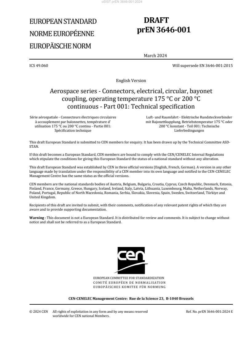
DRAFT
EUROPEAN STANDARD
prEN 3646-001
NORME EUROPÉENNE
EUROPÄISCHE NORM
March 2024
ICS 49.060 Will supersede EN 3646-001:2015
English Version
Aerospace series - Connectors, electrical, circular, bayonet
coupling, operating temperature 175 °C or 200 °C
continuous - Part 001: Technical specification
Série aérospatiale - Connecteurs électriques circulaires Luft- und Raumfahrt - Elektrische Rundsteckverbinder
à accouplement par baïonnettes, température d' mit Bajonettkupplung, Betriebstemperatur 175 °C oder
utilisation 175 °C ou 200 °C continu - Partie 001: 200 °C konstant - Teil 001: Technische
Spécification technique Lieferbedingungen
This draft European Standard is submitted to CEN members for enquiry. It has been drawn up by the Technical Committee ASD-
STAN.
If this draft becomes a European Standard, CEN members are bound to comply with the CEN/CENELEC Internal Regulations
which stipulate the conditions for giving this European Standard the status of a national standard without any alteration.
This draft European Standard was established by CEN in three official versions (English, French, German). A version in any other
language made by translation under the responsibility of a CEN member into its own language and notified to the CEN-CENELEC
Management Centre has the same status as the official versions.
CEN members are the national standards bodies of Austria, Belgium, Bulgaria, Croatia, Cyprus, Czech Republic, Denmark, Estonia,
Finland, France, Germany, Greece, Hungary, Iceland, Ireland, Italy, Latvia, Lithuania, Luxembourg, Malta, Netherlands, Norway,
Poland, Portugal, Republic of North Macedonia, Romania, Serbia, Slovakia, Slovenia, Spain, Sweden, Switzerland, Türkiye and
United Kingdom.
Recipients of this draft are invited to submit, with their comments, notification of any relevant patent rights of which they are
aware and to provide supporting documentation.
Warning : This document is not a European Standard. It is distributed for review and comments. It is subject to change without
notice and shall not be referred to as a European Standard.
EUROPEAN COMMITTEE FOR STANDARDIZATION
COMITÉ EUROPÉEN DE NORMALISATION
EUROPÄISCHES KOMITEE FÜR NORMUNG
CEN-CENELEC Management Centre: Rue de la Science 23, B-1040 Brussels
© 2024 CEN All rights of exploitation in any form and by any means reserved Ref. No. prEN 3646-001:2024 E
worldwide for CEN national Members.
oSIST prEN 3646-001:2024
prEN 3646-001:2024 (E)
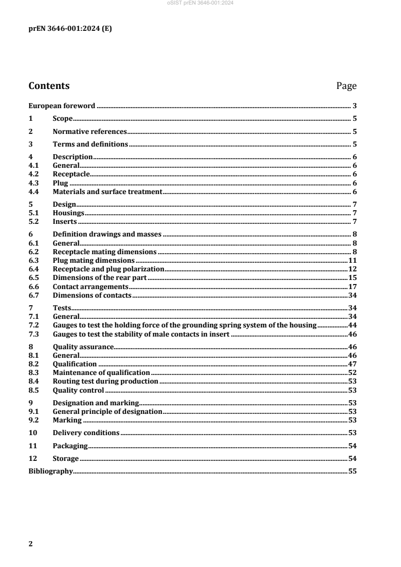
Contents Page
European foreword . 3
1 Scope . 5
2 Normative references . 5
3 Terms and definitions . 5
4 Description . 6
4.1 General . 6
4.2 Receptacle . 6
4.3 Plug . 6
4.4 Materials and surface treatment . 6
5 Design . 7
5.1 Housings . 7
5.2 Inserts . 7
6 Definition drawings and masses . 8
6.1 General . 8
6.2 Receptacle mating dimensions . 8
6.3 Plug mating dimensions . 11
6.4 Receptacle and plug polarization . 12
6.5 Dimensions of the rear part . 15
6.6 Contact arrangements . 17
6.7 Dimensions of contacts . 34
7 Tests . 34
7.1 General . 34
7.2 Gauges to test the holding force of the grounding spring system of the housing . 44
7.3 Gauges to test the stability of male contacts in insert . 46
8 Quality assurance. 46
8.1 General . 46
8.2 Qualification . 47
8.3 Maintenance of qualification . 52
8.4 Routing test during production . 53
8.5 Quality control . 53
9 Designation and marking . 53
9.1 General principle of designation . 53
9.2 Marking . 53
10 Delivery conditions . 53
11 Packaging . 54
12 Storage . 54
Bibliography. 55
oSIST prEN 3646-001:2024
prEN 3646-001:2024 (E)
European foreword
This document (prEN 3646-001:2024) has been prepared by the Aerospace and Defence Industries
Association of Europe - Standardization (ASD-STAN).
This document is currently submitted to the CEN Enquiry.
This document will supersede EN 3646-001:2015.
The main changes compared to the previous edition are as follows:
— normative references updated;
— key and keyway quotation replaced in Figure 3;
— editorial revision of the document.
Any feedback and questions on this document should be directed to the users’ national standards body.
A complete listing of these bodies can be found on the CEN website.
oSIST prEN 3646-001:2024
prEN 3646-001:2024 (E)
Introduction
This family of connectors is derived from MIL-DTL-26482, series 2, the NAS 1599 bayonet connector with
which it is intermateable and which uses AS-39029 for the contacts. It is particularly suitable for use on
aircraft applying EN 2282.
These connectors are distinguishable from MIL-DTL-26482 and NAS 1599 by:
— being of a lower mass;
— having reduced dimensions;
— accepting smaller cables.
oSIST prEN 3646-001:2024
prEN 3646-001:2024 (E)
1 Scope
This document specifies the general characteristics, the conditions for qualification, acceptance and
quality assurance, as well as the test programmes and groups for bayonet coupling circular connectors,
intended for use in an operating temperature range of –65 °C to 175 °C or 200 °C continuous according
to the class and models.
2 Normative references
The following documents are referred to in the text in such a way that some or all of their content
constitutes requirements of this document. For dated references, only the edition cited applies. For
undated references, the latest edition of the referenced document (including any amendments) applies.
EN 2266-002, Aerospace series - Cables, electrical, for general purpose - Operating temperatures between -
55 °C and 200 °C - Part 002: General
EN 2591, Aerospace series — Elements of electrical and optical connection — Test methods
EN 2591-100, Aerospace series — Elements of electrical and optical connection — Test methods —
Part 100: General
EN 3197, Aerospace series - Design and installation of aircraft electrical and optical interconnection systems
EN 3646-002, Aerospace series - Connectors, electrical, circular, bayonet coupling, operating temperature
175 °C or 200 °C continuous - Part 002: Specification of performance and contact arrangements
EN 9133, Aerospace series - Quality Management Systems - Qualification Procedure for Aerospace Standard
Products
ISO 263, ISO inch screw threads — General plan and selection for screws, bolts and nuts — Diameter range
0,06 to 6 in
ISO 27874, Metallic and other inorganic coatings — Electrodeposited gold and gold alloy coatings for
electrical, electronic and engineering purposes — Specification and test methods
MIL-HDBK-454, General guidelines for electronic equipment
3 Terms and definitions
For the purposes of this document, the terms and definitions given in EN 2591-100 apply.
ISO and IEC maintain terminology databases for use in standardization at the following addresses:
— ISO Online browsing platform: available at https://www.iso.org/obp/
— IEC Electropedia: available at https://www.electropedia.org/
All parts quoted in this standard.
Published by: Published by: DEFENSE LOGISTICS AGENCY DLA Land and Maritime (US),
https://landandmaritimeapps.dla.mil/Programs/MilSpec/DocSearch.aspx.
oSIST prEN 3646-001:2024
prEN 3646-001:2024 (E)
4 Description
4.1 General
Different variants of materials, housings and contact arrangements are provided according to the models
depending on the service conditions.
These connectors use crimp or solder contacts of size 20, size 16 and size 12.
The receptacles and plugs contain either male contacts or female contacts.
The contacts fitted in the model Y receptacles are exclusively of the male non-removable solder type.
The connectors are polarized by means of keyways and keys. When all the male contacts are in place,
polarization is obtained by different angular positions of the insulator in relation to the main slot or
locking key and shall occur before the coupling ring can carry out its function.
The visual check of coupling is obtained by viewing the locking pins through the inspection holes in the
coupling ring of the plug.
4.2 Receptacle
The receptacle may be attached by:
— square flange;
— nut, with sealing by O-ring at the attachment;
— round soldered or brazed flange for model Y connectors.
The receptacle contains five keyways in which the keys of the plug engage. The main keyway is fixed and
is wider than the others. Polarization is ensured by the different angular positions of the inserts.
4.3 Plug
The plug contains five keys which engage in the keyways of the receptacle. The main key is wider than
the others. Polarization is ensured by the different angular position of the inserts.
The coupling ring permanently fitted on the plug enables the connectors to be coupled and uncoupled.
The internal guides of the coupling ring may be treated with a suitable lubricant compatible with the
performance required in this standard.
The plug of models RS and WS is fitted with a grounding spring device ensuring electrical continuity
between the coupled connector housings.
4.4 Materials and surface treatment
4.4.1 General
When different metals are in close contact, adequate protection against corrosion shall be used for the
electromotive force of the cell not to exceed 0,25 V according to EN 3197.
4.4.2 Housings
The material of the housing for the connectors and for the fittings may either be passivated stainless steel
or light alloy protected against corrosion by nickel, black anodized or cadmium plating according to
EN 3646-002.
oSIST prEN 3646-001:2024
prEN 3646-001:2024 (E)
4.4.3 Contacts
Unless otherwise specified, the contacts shall be in ferrous alloy for models Y and in copper alloy for the
other models.
They shall be gold-plated on an appropriate undercoat. Selective protection is authorized provided that
it is sufficient to ensure that performance is respected.
Measurement of the thickness of the protective treatment shall be carried out in accordance with
ISO 27874.
4.4.4 Non-metallic materials
The materials used for insert, seals and grommets shall have a hardness and mechanical and electrical
characteristics consistent with the required use.
5 Design
5.1 Housings
The connector housings shall be in one unit. At the rear of the connector housing there shall be either
three teeth at 120° intervals or teeth around the entire periphery. These teeth shall accommodate cable
outlets or other fittings. The receptacle shall furthermore be fitted with an O-ring seal for sealing the
coupled housings.
Receptacles for attachment by nut shall contain an O-ring seal. The nut shall have holes for the passage
of locking wire.
The threads shall conform to ISO 263.
The coupling ring shall be designed so that the male and female contacts engage when it is turned
clockwise and disengaged when it is turned counter-clockwise. The coupling ring shall be knurled.
The cable outlets shall compress the connector grommets without distorting it.
5.2 Inserts
The insert carrying the male and female contacts shall be in hard material and have a cross section and
radii such that no cracks, flaking or breaks can occur in normal operation.
The insert for contacts shall be non-removable; it shall be mechanically held in the housing. Sealing shall
be provided between the housing and insert.
The front face of the insert shall be such that sealing is ensured when the connectors are coupled. The
interfacial seal of the insert of the male contacts shall be bonded on the hard insert.
The grommet shall permit sealing for all cable diameters indicated in EN 3646-002 and shall not be
removable.
The mechanical contacts retention system shall be integrated in the hard insert.
The design of non-hermetic connectors shall permit individual installation of the contacts without
removal of the insert or grommet. Insertion and removal of the contacts shall be from the rear, with the
tools specified in the contact product standards.
oSIST prEN 3646-001:2024
prEN 3646-001:2024 (E)
6 Definition drawings and masses
6.1 General
The general dimensions and the masses of receptacles, plugs and protective covers are specified in the
product standards.
6.2 Receptacle mating dimensions
The mating dimensions of receptacles are shown in Figure 1 and details A and B as well as in Table 1,
Table 2 and Table 3.
oSIST prEN 3646-001:2024
prEN 3646-001:2024 (E)
Dimensions and tolerances in millimetres
Key
1 shells 08 to 18: 5 min.
shells 20 to 24: 6 min.
2 radius or chamfer 0,2 mm to 0,381 mm
3 7°30′ to 11°30′
a position of point of electrical contact
Figure 1 — Receptacle
oSIST prEN 3646-001:2024
prEN 3646-001:2024 (E)
Table 1 — Receptacle — Mating dimensions
A B C D E F H J K
Housing
+0,02 +0,13 0 +0,15
size
max. ±0,18
−0,13 −0,02 −0,4 −0,05
08 12,02 9,19 7,24 14,30
10 14,99 12,44 10,21 17,27
12 19,05 15,41 13,11 21,82
8,38 8,50 0,56
8,00 8,10 0,20
14 22,23 18,59 16,28 24,99
3,55 1,98
16 25,40 21,76 19,46 28,14
18 28,58 24,43 21,72 31,32
20 31,75 27,61 24,89 34,49
9,98 10,10 2,13
22 34,93 30,78 28,07 37,67
9,60 9,70 1,78
24 38,10 33,96 31,22 4,38 40,89 3,18
Table 2 — Details A and B
P Q R U
Contact size
max.
2,29 2,44
1,50
a a
2,13 2,34
20 3,68
2,84 3,00
1,24
2,69 2,89
3,66 3,81 2,06
3,50 3,71 1,80
3,94
5,18 5,33 2,84
5,03 5,23 2,59
a
See Table 3.
Table 3 — Reduced contact cavities
Housing size and contact
Reduced contact cavities
arrangements
8 – 33 A, B, C
8 – 3A or 8 – 98 A, B, C
12 – 10 C, G
14 – 12 A, B, C, D, E, F, G, H
14 – 19 B, D, F, H, K, M
16 – 26 A, B, C, D, E, F, G, H, J, K, L, M, N, P, R
18 – 32 A, B, C, D, E, F, G, H, J, K, L, M, N, P, R, S, T
22 – 41 A, B, C, D, E, F, G, H, J, K, L, M, N, P, R, S, T, U, V, W, X, Y
oSIST prEN 3646-001:2024
prEN 3646-001:2024 (E)
6.3 Plug mating dimensions
The mating dimensions of plugs are shown in Figure 2 and Figure 3 and in Table 4 and Table 5.
Dimensions and tolerances in millimetres
Key
1 Three mated connectors holes (design optional)
2 Reference. Locking point of the coupling ring.
3 Three bayonet groves equally spaced within 0,13 with three holes equally spaced within 0,25 for visual
inspection of coupling (see detail C).
4 Spring ground ring shall have at least six fingers per 25,4 mm of length.
5 Diameter L over spring finger
C Coupling ring bayonet groove detail
a
See Figure 1.
NOTE Diameter C is applicable to female insulators only.
Figure 2 — Plug
oSIST prEN 3646-001:2024
prEN 3646-001:2024 (E)
Table 4 — Plug — Mating dimensions
A B C D E F G J K L M N P X
Housing
+0,10 +0,05 +0,13 +0,39
size
max. max. min. max. min. max. ±0,51
−0,05 −0,10 −0,15 −0,04
08 12,24 9,04 7,24 16,72 14,63 9,37 7,42 4,45
10 15,32 12,29 10,21 19,79 17,70 12,62 10,39
12 19,35 15,14 13,11 23,70 22,12 15,60 13,28
9,22 1,12 9,02
4,75
9,00 0,68 8,56
14 22,50 18,31 16,28 27,40 25,27 18,77 16,46
2,30 2,87
16 25,68 21,49 19,46 30,53 28,44 21,95 19,61
18 28,88 24,03 21,72 33,30 31,62 24,61 21,89
20 32,03 27,20 24,89 37,45 34,79 27,79 25,07 4,75
10,78 2,70 10,59
22 35,20 30,38 28,07 40,45 37,97 30,96 5,54 28,22
10,56 2,26 10,13
24 38,38 33,55 31,22 43,40 41,25 3,50 34,14 31,42 4,45 3,86
6.4 Receptacle and plug polarization
According to Figure 3, Figure 4 and Figure 5 and Table 5 and Table 6.
Dimensions and tolerances in millimetres
Plug Receptacle
Figure 3 — Polarization
oSIST prEN 3646-001:2024
prEN 3646-001:2024 (E)
Table 5 — Polarization dimensions
B J L M α
Housing size
+0,05 +0,08 +0,13 +0,13
−0,10 −0,20 −0,15 −0,02
08 9,04 10,16 10,46 9,19
10 12,29 13,41 13,71 12,44
12 15,14 17,19 17,50 15,41 30'
14 18,31 20,37 20,67 18,59
16 21,49 23,54 23,85 21,76
18 24,03 26,08 26,39 24,43 25'
20 27,20 29,26 29,56 27,61 22'
22 30,38 32,43 32,74 30,78
20'
24 33,55 35,61 35,91 33,96
Figure 4 — Front face view female insulator Figure 5 — Front face view male insulator
oSIST prEN 3646-001:2024
prEN 3646-001:2024 (E)
Table 6 — Polarization of contacts
Polarization (β)
Rating see Table 9 Size and number of
Housing size and
test EN 2591-207 contacts
contact
Polarization code
arrangements
I II 20 16 12 N W X Y Z
08–3A or 8–98 X 3 0 60 210 — —
08–33 X 3 0 90 — — —
10–02 X 2 0 — — — —
10–06 X 6 0 90 — — —
12–03 X 3 0 — — 180 —
12–08 X 8 0 90 112 203 292
12–10 X 10 0 60 155 270 295
14–04 X 4 0 45 — — —
14–05 X 5 0 40 92 184 273
14–12 X 8 4 0 43 90 — —
14–15 X 14 1 0 17 110 155 234
14–19 X 19 0 30 165 315 —
16–08 X 8 0 54 152 180 331
16–21 X 16 5 0 — — — —
16–23 X 22 1 0 158 270 — —
16–26 X 26 0 60 — 275 338
18–08 X 8 0 180 — — —
18–11 X 11 0 62 119 241 340
18–32 X 32 0 85 138 222 265
20–16 X 16 0 238 318 333 347
20–34 X 26 8 0 — — — —
20–39 X 37 2 0 63 144 252 333
20–41 X 41 0 45 126 225 —
22–12 X 12 0 — — — 6
22–21 X 21 0 16 135 175 349
22–36 X 36 0 72 144 216 288
22–41 X 27 14 0 39 135 264 —
22–55 X 55 0 30 142 226 314
24–19 X 19 0 30 165 315 —
24–31 X 31 0 90 225 255 —
24–61 X 61 0 90 180 270 324
oSIST prEN 3646-001:2024
prEN 3646-001:2024 (E)
6.5 Dimensions of the rear part
6.5.1 Model with three teeth
The dimensions of the rear part of receptacles and plugs for models with three teeth with threads for
mounting cable outlets are shown in Figure 6 and in Table 7.
The centre-line of one of the three teeth shall be diametrically opposite to the centre-line of the master
keyway.
Dimensions and tolerances in millimetres
Key
1 Thread (3 threads min.)
2 Grommet
Figure 6 — Rear part
6.5.2 Model with teeth over the entire periphery
The dimensions of the rear part of receptacles and plugs for model with teeth over the entire periphery
with threads for mounting cable outlets are shown in Figure 7 and in Table 7.
oSIST prEN 3646-001:2024
prEN 3646-001:2024 (E)
Key
1 Thread (3 threads min.)
2 Grommet
3 N: number of teeth
Figure 7 — Rear part
Table 7 — Rear part dimensions
a
A B C N Angular
Thread
tolerance of
Housing size
axes
max. min. max. teeth α
0,5000–20
08 7,75 9,40 11,10 12
UNEF-2A
0,6250–24
10 10,29 12,62 14,53 15 ±3
UNEF-2A
0,7500–20
12 13,48 15,57 17,45 21
UNEF-2A
0,8750–20
14 16,89 18,75 20,62 24
UNEF-2A
1,0000–20
16 20,07 21,92 23,80 30 ±2
UNEF-2A
1,0625–18
18 22,07 23,34 25,20 33
UNEF-2A
1,1875–18
20 25,25 26,52 28,37 36
UNEF-2A
1,3125–18
22 28,42 29,69 31,55 39 ±1
UNEF-2A
1,4375–18
24 31,60 32,87 34,72 42
UNEF-2A
a
According to ISO 263.
oSIST prEN 3646-001:2024
prEN 3646-001:2024 (E)
6.6 Contact arrangements
The contact arrangements in the inserts are specified by Figures 8 to 38 which show the front face of
inserts which contains the male contacts, normal polarization position N.
The following tolerances apply to the inserts fitted in the housings:
— centre of each hole;
— centre of each contact end.
Identification of the contact position shall be permanently designed in contrasting colour on the front
face of the insert of interfacial seal and on the rear face of the wire sealing grommet. Identification shall
not be recessed or raised on the sealing surfaces.
Symbols for contact sizes used in this document are as indicated in EN 3155-001:2016, Table A.1.
Housing sizes and contact arrangements according to Figures 8 to 38.
08-3A or 08-98 08-33 10-02
3 contacts, size 20 3 contacts, size 20 2 contacts, size 20
X Y X Y X Y
Contact Contact Contact
mm mm mm mm mm mm
A + 1,65 + 0,94 A 0 + 1,90 A + 2,39 0
B 0 − 1,90 B + 1,65 − 0,97 B − 2,39 0
C − 1,65 + 0,94 C − 1,65 − 0,97
Figure 8 Figure 9 Figure 10
oSIST prEN 3646-001:2024
prEN 3646-001:2024 (E)
10-06 12-03 12-08
6 contacts, size 20 3 contacts, size 16 8 contacts, size 20
X Y X Y X Y
Contact Contact Contact
mm mm mm mm mm mm
A 0 + 3,30 A + 2,39 + 1,47 A + 1,65 + 3,99
B + 2,87 + 1,65 B 0 − 2,82 B + 4,32 0
C + 2,87 − 1,65 C − 2,39 + 1,47 C + 3,05 − 3,05
D 0 − 3,30 D 0 − 4,32
E − 2,87 − 1,65 E − 3,05 − 3,05
F − 2,87 + 1,65 F − 4,32 0
G − 1,65 + 3,99
H 0 + 1,12
Figure 11 Figure 12 Figure 13
oSIST prEN 3646-001:2024
prEN 3646-001:2024 (E)
12-10 14-04 14-05
10 contacts, size 20 4 contacts, size 12 5 contacts, size 16
X Y X Y X Y
Contact Contact Contact
mm mm mm mm mm mm
A 0 + 3,05 A 0 + 4,29 A 0 + 2,54
B + 3,30 + 3,05 B + 4,29 0 B + 4,42 + 0,61
C + 4,95 0 C 0 – 4,29 C + 2,39 – 3,76
D + 3,30 – 3,05 D – 4,29 0 D – 2,39 – 3,76
E 0 – 3,05 E – 4,42 + 0,61
F – 3,30 – 3,05
G – 4,95 0
H – 3,30 + 3,05
J + 1,65 0
K – 1,65 0
Figure 14 Figure 15 Figure 16
oSIST prEN 3646-001:2024
prEN 3646-001:2024 (E)
14-12 14-15
4 contacts, size 16 1 contact, size 16
8 contacts, size 20 14 contacts, size 20
X Y X Y X Y X Y
Contac
Contact Contact Contact
t
mm mm mm mm mm mm mm mm
A + 1,65 + 6,17 G − 4,52 + 4,52 A + 2,54 + 5,71 J − 6,20 + 0,36
B + 4,52 + 4,52 H − 1,65 + 6,17 B + 5,13 + 3,56 K − 5,13 + 3,56
C + 4,52 − 4,52 J 0 + 2,39 C + 6,20 + 0,36 L − 2,54 + 5,71
D + 1,65 − 6,17 K + 4,11 0 D + 5,54 − 2,87 M 0 + 3,56
E − 1,65 − 6,17 L 0 − 2,39 E + 3,20 − 5,31 N + 2,79 + 1,02
F − 4,52 − 4,52 M − 4,11 0 F 0 − 6,22 P 0 − 1,96
G − 3,20 − 5,31 R − 2,79 + 1,02
H − 5,54 − 2,87
Figure 17 Figure 18
oSIST prEN 3646-001:2024
prEN 3646-001:2024 (E)
14-19 16-08
19 contacts, size 20 8 contacts, size 16
X Y X Y X Y
Contact Contact Contact
mm mm mm mm mm mm
A 0 + 5,71 L − 4,95 + 2,87 A 0 + 5,99
B + 3,30 + 5,71 M − 3,30 + 5,71 B + 3,25 + 2,18
C + 4,95 + 2,87 N − 1,65 + 2,87 C + 5,84 − 1,98
D + 6,60 0 P + 1,65 + 2,87 D + 2,39 − 5,49
E + 4,95 − 2,87 R + 3,30 0 E − 2,39 − 5,49
F + 3,30 − 5,71 S + 1,65 − 2,87 F − 5,84 − 1,98
G 0 − 5,71 T − 1,65 − 2,87 G − 3,25 + 2,18
H − 3,30 − 5,71 U − 3,30 0 H 0 − 1,32
J − 4,95 − 2,87 V 0 0
K − 6,60 0
Figure 19 Figure 20
oSIST prEN 3646-001:2024
prEN 3646-001:2024 (E)
16-21
5 contacts, size 16
16 contacts, size 20
X Y X Y X Y
Contact Contact Contact
mm mm mm mm mm mm
A 0 + 8,15 H + 1,70 − 7,98 R − 3,32 + 7,45
B + 3,32 + 7,45 J − 1,70 − 7,98 S + 2,45 + 3,37
C + 6,06 + 5,46 K − 4,79 − 6,60 T + 3,96 − 1,29
D + 7,76 + 2,52 L − 7,06 − 4,08 U 0 − 4,17
E + 8,11 − 0,85 M − 8,11 − 0,85 V − 3,96 − 1,29
F + 7,06 − 4,08 N − 7,76 + 2,52 X − 2,45 + 3,37
G + 4,79 − 6,60 P − 6,06 + 5,46 Y 0 0
Figure 21
oSIST prEN 3646-001:2024
prEN 3646-001:2024 (E)
16-23
16-26
1 contact, size 16
26 contacts, size 20
22 contacts, size 20
X Y X Y X Y X Y
Contact Contact Contact Contact
mm mm mm mm mm mm mm mm
A + 1,78 + 7,62 N − 4,90 + 6,10 A 0 + 8,15 P − 6,07 + 5,44
B + 4,90 + 6,10 P − 1,78 + 7,62 B + 3,33 + 7,44 R − 3,33 + 7,44
C + 7,06 + 3,40 R 0 + 4,52 C + 6,07 + 5,44 S − 1,78 + 4,50
D + 7,82 0 S + 3,20 + 3,20 D + 7,75 + 2,51 T + 1,78 + 4,50
E + 7,06 − 3,40 T + 4,52 0 E + 8,10 − 0,86 U + 4,44 + 2,39
F + 4,90 − 6,10 U + 3,20 − 3,20 F + 7,06 − 4,09 V + 4,52 − 0,91
G + 1,78 − 7,62 V 0 − 4,52 G + 4,80 − 6,60 W + 3,02 − 3,83
H − 1,78 − 7,62 W − 3,20 − 3,20 H + 1,70 − 7,98 X 0 − 5,16
J − 4,90 − 6,10 X − 4,52 0 J − 1,70 − 7,98 Y − 3,02 − 3,83
K − 7,06 − 3,40 Y − 3,20 + 3,20 K − 4,80 − 6,60 Z − 4,52 − 0,91
L − 7,82 0 Z 0 0 L − 7,06 − 4,09 a − 4,44 + 2,39
M − 7,06 + 3,40 M − 8,10 − 0,86 b 0 + 1,65
N − 7,75 + 2,51 c 0 − 1,65
Figure 22 Figure 23
oSIST prEN 3646-001:2024
prEN 3646-001:2024 (E)
18-08 18-11
8 contacts, size 12 11 contacts, size 16
X Y X Y X Y X Y
Contact Contact Contact Contact
mm mm mm mm mm mm mm mm
A 0 + 7,11 E − 3,07 − 6,40 A + 2,67 + 6,60 G − 6,99 − 1,35
B + 5,56 + 4,45 F − 6,93 − 1,57 B + 6,35 + 3,35 H − 6,35 + 3,35
C + 6,93 − 1,57 G − 5,56 + 4,45 C + 6,99 − 1,35 J − 2,67 + 6,60
D + 3,07 − 6,40 H 0 0 D + 4,55 − 5,46 K 0 + 2,67
E 0 − 7,14 L 0 − 2,34
F − 4,55 − 5,46
Figure 24 Figure 25
oSIST prEN 3646-001:2024
prEN 3646-001:2024 (E)
18-32
32 contacts, size 20
X Y X Y X Y X Y
Contact Contact Contact Contact
mm mm mm mm mm mm mm mm
A + 1,68 + 8,97 J 0 − 9,12 T − 1,68 + 8,97 b − 4,42 − 3,83
B + 4,80 + 7,75 K − 3,30 − 8,51 U 0 + 5,84 c − 5,79 − 0,84
C + 7,26 + 5,51 L − 6,15 − 6,73 V + 3,15 + 4,90 d − 5,31 + 2,41
D + 8,76 + 2,49 M − 8,15 − 4,06 W + 5,31 + 2,41 e − 3,15 + 4,90
E + 9,07 − 0,84 N − 9,07 − 0,84 X + 5,79 − 0,84 f 0 + 2,44
F + 8,15 − 4,06 P − 8,76 + 2,49 Y + 4,42 − 3,83 g + 2,44 0
G + 6,15 − 6,73 R − 7,26 + 5,51 Z + 1,65 − 5,61 h 0 − 2,44
H + 3,30 − 8,51 S − 4,80 + 7,75 a − 1,65 − 5,61 j − 2,44 0
Figure 26
oSIST prEN 3646-001:2024
prEN 3646-001:2024 (E)
20-16
16 contacts, size 16
X Y X Y X Y X Y
Contact Contact Contact Contact
mm mm mm mm mm mm mm mm
A + 3,00 + 8,18 E + 4,62 − 7,37 J − 8,66 + 0,91 N + 3,91 + 1,57
B + 6,88 + 5,36 F 0 − 8,71 K − 6,88 + 5,36 P + 2,39 − 3,10
C + 8,66 + 0,91 G − 4,62 − 7,37 L − 3,00 + 8,18 R − 2,39 − 3,10
D + 7,82 − 3,81 H − 7,82 − 3,81 M 0 + 4,44 S − 3,91 + 1,57
Figure 27
oSIST prEN 3646-001:2024
prEN 3646-001:2024 (E)
20-34 20-39
26 contacts, size 20 2 contacts, size 16
8 contacts, size 16 37 contacts, size 20
X Y X Y X Y X Y
Contact Contact Contact Contact
mm mm mm mm mm mm mm mm
A 0 + 10,62 U − 8,58 + 6,22 A + 1,65 + 10,44 X 0 + 7,49
B + 3,28 + 10,08 V − 6,22 + 8,58 B + 4,80 + 9,42 Y + 3,20 + 6,50
C + 6,22 + 8,58 W − 3,28 + 10,08 C + 7,47 + 7,47 Z + 5,89 + 4,55
D + 8,58 + 6,22 X 0 + 7,10 D + 9,42 + 4,80 a + 7,11 + 1,45
E + 10,08 + 3,28 Y + 3,90 + 5,30 E + 10,44 + 1,65 b + 7,11 − 1,88
F + 10,62 0 Z + 6,42 + 1,42 F + 10,44 − 1,65 c + 5,51 − 4,80
G + 10,08 − 3,28 a + 5,78 − 3,16 G + 9,42 − 4,80 d + 2,84 − 6,73
H + 8,58 − 6,22 b + 2,27 − 6,17 H + 7,47 − 7,47 e − 2,84 − 6,73
J + 6,22 − 8,58 c − 2,27 − 6,17 J + 4,80 − 9,42 f − 5,51 − 4,80
K + 3,28 − 10,08 d − 5,78 − 3,16 K + 1,65 − 10,44 g − 7,11 − 1,88
L 0 − 10,62 e − 6,42 + 1,42 L − 1,65 − 10,44 h − 7,11 + 1,45
M − 3,28 − 10,08 f − 3,90 + 5,30 M − 4,80 − 9,42 i − 5,89 + 4,55
N − 6,22 − 8,58 g 0 + 3,80 N − 7,47 − 7,47 j − 3,20 + 6,50
P − 8,58 − 6,22 h + 2,20 + 1,12 P − 9,42 − 4,80 k 0 + 4,17
R − 10,08 − 3,28 i + 1,70 − 2,10 R − 10,44 − 1,65 m + 2,90 + 1,22
S − 10,62 0 j − 1,70 − 2,10 S − 0,44 + 1,65 n + 2,69 − 2,72
T − 10,08 + 3,28 k − 2,20 + 1,12 T − 9,42 + 4,80 p 0 − 4,80
U − 7,47 + 7,47 q − 2,69 − 2,72
V − 4,80 + 9,42 r − 2,90 + 1,22
W − 1,65 + 10,44
Figure 28 Figure 29
oSIST prEN 3646-001:2024
prEN 3646-001:2024 (E)
20-41
41 contacts, size 20
Contact X Y Contact X Y Contact X Y Contact X Y Contact X Y
mm mm mm mm mm mm mm mm
A 0 +10,61 K + 3,28 – 1009 V – 6,23 + 8,58 e – 1,72 – 6,99 p + 1,65 – 3,43
B + 3,28 +10,09 L 0 – 10,61 W – 3,28 + 10,09 f – 4,77 – 5,39 q – 1,65 – 3,43
C + 6,23 +8,58 M – 3,28 – 10,09 X 0 + 7,21 g – 6,73 – 2,57 r – 3,71 – 0,84
D + 8,58 +6,23 N – 6,23 – 8,58 Y + 3,35 + 6,38 h – 7,14 + 0,87 s – 2,98 + 2,38
E + 10,09 +3,28 P – 8,58 – 6,23 Z + 5,92 + 4,09 i – 5,92 + 4,09 t 0 0
F + 10,61 R – 10,09 – 3,28 a +7,14 + 0,87 j – 3,35 + 6,38
G + 10,09 3,28 S – 10,61 0 b +6,73 – 2,57 k 0 + 3,81
H + 8,58 –6,23 T – 10,09 + 3,28 c +4,77 – 5,39 m + 2,98 + 2,38
J + 6,23 –8,58 U – 8,58 + 6,23 d +1,72 – 6,99 n + 3,71 – 0,84
Figure 30
oSIST prEN 3646-001:2024
prEN 3646-001:2024 (E)
22-12
12 contacts, size 12
X Y X Y X Ym
Contact Contact Contact
mm mm mm mm mm mm
A 0 + 10,11 E + 3,45 − 9,50 J − 6,50 + 7,75
B + 6,50 + 7,75 F − 3,45 − 9,50 K + 3,33 + 1,91
C + 9,96 + 1,75 G − 8,76 − 5,05 L 0 − 3,83
D + 8,76 − 5,05 H − 9,96 + 1,75 M − 3,33 + 1,91
Figure 31
oSIST prEN 3646-001:2024
prEN 3646-001:2024 (E)
22-21 22-36
21 contacts, size 16 36 contacts, size 20
X Y X Y X Y X Y
Contact Contact Contact Contact
mm mm mm mm mm mm mm mm
A + 3,25 + 9,78 M − 7,34 + 7,24 A + 2,54 + 11,43 V + 3,81 + 6,98
B + 7,34 + 7,24 N − 3,25 + 9,78 B + 6,35 + 10,16 W + 7,62 + 3,17
C + 9,80 + 3,12 P 0 + 6,22 C + 8,89 + 6,98 X + 7,62 − 0,64
D + 0,16 − 1,65 R + 4,06 + 3,71 D + 11,43 + 2,54 Y + 6,99 − 4,44
E + 8,33 − 6,07 S + 5,44 − 0,89 E + 11,43 − 1,27 Z + 3,81 − 6,98
F + 4,65 − 9,19 T + 2,39 − 4,93 F + 10,80 − 5,08 a 0 − 7,62
G 0 − 10,31 U − 2,39 − 4,93 G + 7,62 − 8,89 b − 3,81 − 6,98
H − 4,65 − 9,19 V − 5,44 − 0,89 H + 3,81 − 10,79 c + 6,99 – 4,44
J − 8,33 − 6,07 W − 4,06 + 3,71 J 0 − 11,43 d − 7,62 – 0,64
K − 10,16 − 1,65 X 0 0 K − 3,81 − 10,79 e − 7,62 + 3,17
L − 9,80 + 3,12 L − 7,62 − 8,89 f − 3,81 + 6,98
M − 10,80 − 5,08 g 0 + 3,81
N − 11,43 − 1,27 h + 3,81 + 3,17
P − 11,43 + 2,54 j + 3,81 − 0,64
R − 8,89 + 6,98 k 0 − 3,81
S − 6,35 + 10,16 l − 3,81 − 0,64
T − 2,54 + 11,43 m − 3,81 + 3,17
U 0 + 8,25 n 0 0
Figure 32 Figure 33
oSIST prEN 3646-001:2024
prEN 3646-001:2024 (E)
22-41
22-55
14 contacts, size 16
55 contacts, size 20
27 contacts, size 20
X Y X Y X Y X Y
Contact Contact Contact Contact
mm mm mm mm mm mm mm mm
A + 3,35 + 11,99 Y − 3,35 + 11,99 A + 2,84 + 11,56 f − 2,84 − 8,25
B +6,48 + 10,62 Z 0 + 9,55 B + 5,72 + 9,91 g − 5,72 − 6,60
C + 9,09 + 8,48 a + 4,14 + 7,16 C + 8,53 + 8,25 h − 8,53 − 4,95
D + 11,04 + 5,71 b + 7,59 + 4,39 D + 11,43 + 3,30 i − 8,53 − 1,65
E + 12,19 + 2,51 c + 8,28 0 E + 11,43 0 j − 8,53 + 1,65
F + 12,42 − 0,86 d + 7,82 − 4,39 F + 11,43 − 3,30 k − 8,53 + 4,95
G + 11,73 − 4,19 e + 4,14 − 7,16 G + 8,53 − 8,25 m − 5,72 + 6,60
H + 10,16 − 7,19 f 0 −8,74 H + 5,72 − 9,91 n − 2,84 + 8,25
J + 7,82 − 9,68 g − 4,14 − 7,16 J + 2,84 − 11,56 p 0 + 6,60
K + 4,93 − 11,43 h − 7,82 − 4,39 K − 2,84 − 11,56 q + 2,84 + 4,95
L + 1,70 − 12,34 i − 8,28 0 L − 5,72 − 9,91 r + 5,72 + 3,30
M − 1,70 − 12,34 j − 7,59 + 4,39 M − 8,53 − 8,25 s + 5,72 0
N − 4,93 − 11,43 k − 4,14 + 7,16 N − 11,43 − 3,30 t + 5,72 − 3,30
P − 7,82 − 9,68 m + 4,77 P − 11,43 0 u + 2,84 − 4,95
R − 10,16 − 7,19 n + 4,14 + 2,39 R − 11,43 + 3,30 v 0 − 6,60
S − 11,73 − 4,19 p + 4,14 − 2,39 S − 8,53 + 8,25 w − 2,84 − 4,95
T − 12,42 − 0,86 q 0 − 4,77 T − 5,72 + 9,91 x − 5,72 − 3,30
U − 12,19 + 2,51 r − 4,14 − 2,39 U − 2,84 + 11,56 y − 5,72 0
V − 11,04 + 5,71 s − 4,14 + 2,39 V 0 + 9,91 z − 5,72 + 3,30
W − 9,09 + 8,48 t 0 0 W + 2,84 + 8,25 AA − 2,84 + 4,95
X − 6,48 + 10,62 X + 5,72 + 6,60 BB 0 + 3,30
Y + 8,53 + 4,95 CC + 2,84 + 1,65
Z + 8,53 + 1,65 DD + 2,84 − 1,65
a + 8,53 − 1,65 EE 0 − 3,30
b + 8,53 − 4,95 FF − 2,84 − 1,65
c + 5,72 − 6,60 GG − 2,84 + 1,65
d + 2,84 − 8,25 HH 0 0
e 0 − 9,91
Figure 34 Figure 35
oSIST prEN 3646-001:2024
prEN 3646-001:2024 (E)
24-19 24-31
19 contacts, size 12 31 contacts, size 16
X Y X Y X Y X Y
Contact Contact Contact Contact
mm mm mm mm mm mm mm mm
A 0 + 10,46 L − 9,07 + 5,23 A + 4,01 + 11,56 S + 8,03 − 4,62
B + 6,04 + 10,46 M − 6,04 + 0,46 B + 8,03 + 9,25 T + 4,01 − 6,93
C + 9,07 + 5,23 N − 3,02 + 5,23 C + 12,04 + 2,31 U 0 − 9,25
D + 12,09 0 P + 3,02 + 5,23 D + 12,04 − 2,31 V − 4,01 − 6,93
E + 9,07 − 5,23 R + 6,04 0 E + 8,03 − 9,25 W − 8,03 − 4,62
F + 6,04 − 10,46 S + 3,02 − 5,23 F + 4,01 − 11,56 X − 8,03 0
G 0 − 0,46 T − 3,02 − 5,23 G − 4,01 − 11,56 Y − 8,03 + 4,62
H − 6,04 − 10,46 U − 6,04 0 H − 8,03 − 9,25 Z − 4,01 + 6,93
J − 9,07 − 5,23 V 0 0 J − 12,04 − 2,31 a 0 + 4,62
K − 12,09 0 K − 12,04 + 2,31 b + 4,01 + 2,31
L − 8,03 + 9,25 c + 4,01 − 2,31
M − 4,01 + 11,56 d 0 − 4,62
N 0 + 9,25 e − 4,01 − 2,31
P + 4,01 + 6,93 f − 4,01 + 2,31
Q + 8,03 + 4,62 g 0 0
R + 8,03 0
Figure 36 Figure 37
oSIST prEN 3646-001:2024
prEN 3646-001:2024 (E)
24-61
61 contacts, size 20
X Y X Y X Y
Contact Contact Contact
mm mm mm mm mm mm
A + 4,98 + 12,70 Y − 7,98 + 11,05 v 0 + 8,58
B + 7,98 + 11,05 Z − 4,98 + 12,70 w + 3,73 + 5,66
C + 10,49 + 8,71 a − 1,73 + 11,53 x + 6,02 + 3,10
D + 12,32 + 5,84 b + 1,73 + 11,53 y + 6,78 + 0,25
E + 13,39 + 2,57 c + 4,39 + 9,22 z + 5,79 − 3,53
F + 13,61 − 0,76 d + 7,24 + 7,19 AA + 3,33 − 5,92
G + 12,98 − 4,17 e + 9,19 + 4,44 BB 0 − 6,78
H + 11,53 − 7,29 f + 10,13 + 1,17 CC − 3,33 − 5,92
J + 9,35 − 9,93 g + 9,97 − 2,23 DD − 5,79 − 3,53
K + 6,58 − 11,94 h + 8,66 − 5,41 EE − 6,78 + 0,25
L + 3,40 − 13,18 i + 6,37 − 7,98 FF − 6,02 + 3,10
M 0 − 13,64 j + 3,38 − 9,63 GG − 3,73 + 5,66
N − 3,40 − 13,18 k 0 − 10,21 HH 0 + 5,08
P − 6,58 − 11,94 m − 3,38 − 9,63 JJ + 2,67 + 2,39
R − 9,35 − 9,93 n − 6,37 − 7,98 KK + 3,43 − 1,04
S − 11,53 − 7,29 p − 8,66 − 5,41 LL 0 − 3,35
T − 12,98 − 4,17 q − 9,97 − 2,23 MM − 3,43 − 1,04
U − 13,61 − 0,76 r − 10,13 + 1,17 NN − 2,67 + 2,39
V − 13,39 + 2,57 s − 9,19 + 4,44 PP 0 0
W − 12,32 + 5,84 t − 7,24 + 7,19
X − 10,49 + 8,71 u − 4,39 + 9,22
Figure 38
oSIST prEN 3646-001:2024
prEN 3646-001:2024 (E)
6.7 Dimensions of contacts
6.7.1 Removable contacts
Standards for contacts are given in EN 3646-002.
6.7.2 Fixed contacts
The dimensions of fixed solder contacts, models Y, are given in detail B of Figure 1 for the front part, and
in Figure 39 and Table 8 for the dimensions of the barrel.
Key
1 Optional radius
Figure 39 — Dimensions of the barrel
Table 8 — Dimensions of the barrel
A B D E
Contact
1,60
size
−0,41
min. ± 0,79
2,23
20 1,07 3,17 2,39
1,55
2,94
16 1,75 4,77 3,17
2,44
3,81
12 2,85 4,77 3,17
3,30
7 Tests
7.1 General
The tests of EN 2591-100, applicable in the context of this standard as well as the details necessary for
implementing them and for inspecting connector characteristics, are given in Table 9.
oSIST prEN 3646-001:2024
prEN 3646-001:2024 (E)
Table 9 — Tests
EN 2591- Designation of the test Details
101 Visual examination Initial examination: examination of connectors,
fittings, loose parts (contacts, etc.)
Details to be examined:
— identification;
— appearance;
— marking;
— surface finish.
Final examination: no loosening of parts, no crack,
excessive wear, detached part shall be observed.
102 Examination of dimensions and According to Clause 6 and product standard. The
mass checking of inaccessible dimensions on the
finished product shall be carried out on part
pieces or given by the quality organization of the
manufacturer concerned.
201 Contact resistance — Low level Not applicable
202 Contact resistance at rated Crimp contacts: defined by the standards for
current contacts specified in EN 3646-002
Solder contacts (hermetic connectors): measuring
points on the cable, nearest to the contacts
Contact Current Maximum contact
size resistance
mΩ
A Initial After tests
EN 2591-301
and
EN 2591-307
20 5 12 15
16 10 8 10
12 17 5 6
203 Electrical continuity at microvolt Not applicable
level
204 Discontinuity of contacts in the Duration of micro-discontinuity: ≤ 1 µs
microsecond range
Method B
Test time: throughout the duration of tests
EN 2591-301, EN 2591-402 and EN 2591-403
205 Housing (shell) electrical 5 mΩ — plug with grounding spring system and
continuity receptacle
50 mΩ — plug with grounding spring system and
hermetic receptacle
oSIST prEN 3646-001:2024
prEN 3646-001:2024 (E)
EN 2591- Designation of the test Details
206 Measurement of insulation Method A, connectors uncoupled, unless
resistance otherwise indicated below
Minimum insulation resistance:
— at ambient temperature: 1 000 MΩ (unmated
connectors);
— maximum operating temperature: 500 MΩ
(unmated connectors);
— after tests EN 2591-314, EN 2591-321,
EN 2591-324:1 000 MΩ (mated connectors);
— after tests EN 2591-315 and EN 2591-316:
1 000 MΩ (unmated connectors);
— during test EN 2591-321: 100 MΩ (mated
connectors).
207 Voltage proof test Method A, connectors uncoupled except for tests
EN 2591-314 and EN 2591-324 and during
EN 2591-302 where they shall be mated
For tests at low pressure, voltage is applied after
30 min at the pressure indicated.
Voltage value
Rating I Rating I
...