


ISO/IEC 24956:2026
(Main)Information technology — 3D printing and scanning — Phantom-based evaluation methods for 3D printing modeling software
General Information
- Abstract
This document defines an evaluation procedure and evaluation methods for assessing the accuracy and precision of 3D modelling software for designing 3D printing models using phantoms. This document is not intended to evaluate the 3D-printed product itself.
- Status
- Published
- Publication Date
- 02-Sep-2026
- Technical Committee
- ISO/IEC JTC 1 - Information technology
- Drafting Committee
- ISO/IEC JTC 1/WG 12 - 3D Printing and scanning
- Current Stage
- 6060 - International Standard published
- Start Date
- 03-Sep-2026
- Due Date
- 20-Dec-2027
- Completion Date
- 03-Sep-2026


Overview
ISO/IEC 24956:2026 is an international standard specifically designed to define evaluation procedures and methods for assessing the accuracy and precision of 3D modeling software used in 3D printing workflows, utilizing phantom-based testing. Developed by ISO and IEC, this standard addresses the critical need for reliable, objective, and standardized methods to gauge the performance of 3D modeling software during the modeling phase, without evaluating the final 3D-printed product itself. With the continued expansion of 3D scanning and printing applications across medical, industrial, and research fields, precision in digital models is essential to minimize cumulative errors and ensure high-quality outcomes.
Key Topics
Phantom-Based Evaluation:
The standard introduces the use of reference objects called phantoms-designed with well-defined and quantifiable properties-to objectively test and benchmark the accuracy and precision of 3D modeling software.Quality Control in 3D Modeling:
ISO/IEC 24956:2026 emphasizes quality control throughout the modeling process, including image acquisition, segmentation, 3D modeling, and refinement phases. Each phase contributes to the overall reliability of the digital model intended for 3D printing.Evaluation Criteria and Methods:
The document highlights critical software assessment categories such as geometric, spatial, volumetric, and surface accuracy, as well as repeatability, reproducibility, user-friendliness, performance, and regulatory compliance.Advantages of Using Phantoms:
Utilizing phantoms provides standardized and objective benchmarks, repeatable testing, realism by mimicking actual use cases, and cost-effectiveness compared to real-world trials with physical objects.
Applications
ISO/IEC 24956:2026 supports a wide range of applications in additive manufacturing and digital modeling:
Medical 3D Printing:
Ensures software used for modeling anatomical structures from CT or MRI scans produces accurate and precise models essential for surgical planning or prosthetics design.Industrial Design and Manufacturing:
Enables manufacturers to validate the software used for reverse engineering, custom part fabrication, and remanufacturing, ensuring dimensional fidelity and reducing risk of production errors.Research and Development:
Provides researchers with a reliable framework for benchmarking new 3D modeling software tools, supporting innovation in 3D scanning and printing technologies.Quality Assurance Programs:
Assists organizations in complying with best practices for digital model accuracy and in establishing effective QA protocols for additive manufacturing processes.
Related Standards
ISO/ASTM 52920:
Requirements for industrial additive manufacturing processes and production sites, complementing software evaluation by covering production aspects.ISO/IEC 3532-1 and 3532-2:
Define workflows for generating 3D models from scanned data and detail requirements for segmentation phases.ISO/IEC 8803:
Specifies 3D printing quality lifecycle and methods to relate quality measures to workflow phases.ASTM E2339 (DICONDE):
Standard for digital imaging in non-destructive evaluation, relevant for image acquisition in industrial CT and NDE applications.
For organizations and professionals involved in 3D printing, additive manufacturing, and high-fidelity digital modeling, ISO/IEC 24956:2026 is an essential resource for ensuring modeling software is rigorously evaluated, leading to improved quality and reliability in 3D printed applications. Incorporating phantom-based evaluation methods enhances objective assessment, supports regulatory compliance, and fosters greater trust in digital manufacturing technologies.
Get Certified
Connect with accredited certification bodies for this standard

BSI Group
BSI (British Standards Institution) is the business standards company that helps organizations make excellence a habit.

BSCIC Certifications Pvt. Ltd.
Established 2006, accredited by NABCB, JAS-ANZ, EIAC, IAS. CDSCO Notified Body.

Intertek India Pvt. Ltd.
Delivers Assurance, Testing, Inspection & Certification since 1993 with 26 labs and 32 offices.
Sponsored listings
Frequently Asked Questions
ISO/IEC 24956:2026 is a standard published by the International Organization for Standardization (ISO). Its full title is "Information technology — 3D printing and scanning — Phantom-based evaluation methods for 3D printing modeling software". This standard covers: This document defines an evaluation procedure and evaluation methods for assessing the accuracy and precision of 3D modelling software for designing 3D printing models using phantoms. This document is not intended to evaluate the 3D-printed product itself.
This document defines an evaluation procedure and evaluation methods for assessing the accuracy and precision of 3D modelling software for designing 3D printing models using phantoms. This document is not intended to evaluate the 3D-printed product itself.
ISO/IEC 24956:2026 is classified under the following ICS (International Classification for Standards) categories: 35.020 - Information technology (IT) in general; 35.080 - Software. The ICS classification helps identify the subject area and facilitates finding related standards.
ISO/IEC 24956:2026 is available in PDF format for immediate download after purchase. The document can be added to your cart and obtained through the secure checkout process. Digital delivery ensures instant access to the complete standard document.
Standards Content (Sample)
International
Standard
ISO/IEC 24956
First edition
Information technology — 3D
2026-09
printing and scanning — Phantom-
based evaluation methods for 3D
printing modeling software
Reference number
© ISO/IEC 2026
All rights reserved. Unless otherwise specified, or required in the context of its implementation, no part of this publication may
be reproduced or utilized otherwise in any form or by any means, electronic or mechanical, including photocopying, or posting on
the internet or an intranet, without prior written permission. Permission can be requested from either ISO at the address below
or ISO’s member body in the country of the requester.
ISO copyright office
CP 401 • Ch. de Blandonnet 8
CH-1214 Vernier, Geneva
Phone: +41 22 749 01 11
Email: copyright@iso.org
Website: www.iso.org
Published in Switzerland
© ISO/IEC 2026 – All rights reserved
ii
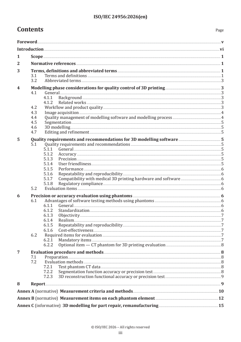
Contents Page
Foreword .v
Introduction .vi
1 Scope . 1
2 Normative references . 1
3 Terms, definitions and abbreviated terms . 1
3.1 Terms and definitions .1
3.2 Abbreviated terms .3
4 Modelling phase considerations for quality control of 3D printing . 3
4.1 General .3
4.1.1 Background .3
4.1.2 Related works .3
4.2 Workflow and product quality .3
4.3 Image acquisition .4
4.4 Quality management of modelling software and modelling process .4
4.5 Segmentation .5
4.6 3D modelling . .5
4.7 Editing and refinement .5
5 Quality requirements and recommendations for 3D modelling software . 5
5.1 Quality requirements and recommendations .5
5.1.1 General .5
5.1.2 Accuracy .5
5.1.3 Precision .5
5.1.4 User friendliness .5
5.1.5 Performance .6
5.1.6 Repeatability and reproducibility .6
5.1.7 Compatibility with medical 3D printing hardware and software .6
5.1.8 Regulatory compliance .6
5.2 Evaluation items .6
6 Precision or accuracy evaluation using phantoms . 6
6.1 Advantages of software testing methods using phantoms .6
6.1.1 General .6
6.1.2 Standardization .6
6.1.3 Objectivity .7
6.1.4 Realism.7
6.1.5 Repeatability and reproducibility .7
6.1.6 Cost-effectiveness . .7
6.2 Required items for evaluation .7
6.2.1 Mandatory items .7
6.2.2 Optional item — CT phantom for 3D printing evaluation .8
7 Evaluation procedure and methods . 8
7.1 Preparation .8
7.2 Evaluation methods .8
7.2.1 Test phantom CT data .8
7.2.2 Segmentation function accuracy or precision test .8
7.2.3 3D reconstruction functional accuracy or precision test .9
8 Report . 9
Annex A (normative) Measurement criteria and methods .10
Annex B (normative) Measurement items on each phantom element .12
Annex C (informative) 3D modelling for part repair, remanufacturing .15
© ISO/IEC 2026 – All rights reserved
iii
Annex D (informative) Non-destructive, 3D scanning of internal and external geometries
benefits of CT scanning . 17
Annex E (informative) Assessment metrics of image-based 3D modelling .20
Annex F (informative) Evaluation report template .21
Bibliography .23
© ISO/IEC 2026 – All rights reserved
iv
Foreword
ISO (the International Organization for Standardization) and IEC (the International Electrotechnical
Commission) form the specialized system for worldwide standardization. National bodies that are
members of ISO or IEC participate in the development of International Standards through technical
committees established by the respective organization to deal with particular fields of technical activity.
ISO and IEC technical committees collaborate in fields of mutual interest. Other international organizations,
governmental and non-governmental, in liaison with ISO and IEC, also take part in the work.
The procedures used to develop this document and those intended for its further maintenance are described
in the ISO/IEC Directives, Part 1. In particular, the different approval criteria needed for the different types
of document should be noted. This document was drafted in accordance with the editorial rules of the ISO/
IEC Directives, Part 2 (see www.iso.org/directives or www.iec.ch/members_experts/refdocs).
ISO and IEC draw attention to the possibility that the implementation of this document may involve the
use of (a) patent(s). ISO and IEC take no position concerning the evidence, validity or applicability of any
claimed patent rights in respect thereof. As of the date of publication of this document, ISO and IEC had not
received notice of (a) patent(s) which may be required to implement this document. However, implementers
are cautioned that this may not represent the latest information, which may be obtained from the patent
database available at www.iso.org/patents and https://patents.iec.ch. ISO and IEC shall not be held
responsible for identifying any or all such patent rights.
Any trade name used in this document is information given for the convenience of users and does not
constitute an endorsement.
For an explanation of the voluntary nature of standards, the meaning of ISO specific terms and expressions
related to conformity assessment, as well as information about ISO's adherence to the World Trade
Organization (WTO) principles in the Technical Barriers to Trade (TBT) see www.iso.org/iso/foreword.html.
In the IEC, see www.iec.ch/understanding-standards.
This document was prepared by Joint Technical Committee ISO/IEC JTC 1, Information technology.
Any feedback or questions on this document should be directed to the user’s national standards
body. A complete listing of these bodies can be found at www.iso.org/members.html and
www.iec.ch/national-committees.
© ISO/IEC 2026 – All rights reserved
v
Introduction
This document was developed in response to the needs of quality management of 3D printing and scanning
technology by taking full advantage of information and communication technology (ICT).
3D scanning is the process of scanning a real-world object or environment to collect data on its shape and
possibly its style attributes. The main purpose of 3D scanning is for generating high-precision digital 3D
models by non-destructive, 3D scanning of internal and external geometries.
A 3D scanner can be based on many different technologies, each with its own purposes and targets,
limitations, and advantages. There can be many limitations in each type of target object that will be digitized.
For example, optical technology can encounter many difficulties with dark, shiny, reflective, or transparent
objects. Another example is the use of computed tomography (CT) scanning, structured-light 3D scanners,
and LiDAR technology, which highlights the need for non-destructive internal scanning methods to generate
digital 3D models.
Despite the rapid growth of 3D scanning applications, the accuracy, precision, and reproducibility of 3D
models generated from 3D scanned data have not been thoroughly investigated. When scanned data are
used for 3D printing, their accuracy and precision are critical. Inaccuracies may arise during imaging,
segmentation, postprocessing, and printing. The overall accuracy, precision, and reproducibility of 3D
printed models are influenced by the cumulative errors introduced at each step in the model creation
process.
For the continued expansion of 3D printing applications, it is necessary to review and evaluate the various
factors in each step of the 3D model printing process that contribute to 3D model inaccuracy, including the
intrinsic limitations of each printing technology.
— In this context evaluation of the overall process of data processing is critical.
— For minimization of cumulative errors of 3D printing life cycles using 3D scanned data, the initial error
should be assessed and corrected.
— The assessment methods of 3D scanned data for 3D printing are essential.
Establishing a reliable and practical evaluation method for 3D modelling software is crucial for ensuring
the quality and dependability of 3D models used in 3D printing. Standard CT performance evaluation
phantoms and existing phantoms make evaluating the performance of 3D printing modelling challenging. A
dependable and practical approach to evaluating the performance of 3D modelling software for 3D printing
is essential and would benefit a wide range of stakeholders, including developers of 3D modelling software,
manufacturers, and researchers. A phantom-based evaluation method can provide a reliable and practical
way to evaluate the performance of 3D modelling software in the context of 3D printing. This would serve
as a valuable tool for assessing the quality and dependability of 3D modelling software, which is crucial for
ensuring the precision and safety of 3D printing applications.
This document proposes evaluation methods for 3D modelling software that use CT phantoms to assess
quality enhancement and error minimization in 3D printed model.
© ISO/IEC 2026 – All rights reserved
vi
International Standard ISO/IEC 24956:2026(en)
Information technology — 3D printing and scanning —
Phantom-based evaluation methods for 3D printing modeling
software
1 Scope
This document defines an evaluation procedure and evaluation methods for assessing the accuracy and
precision of 3D modelling software for designing 3D printing models using phantoms.
This document is not intended to evaluate the 3D-printed product itself.
2 Normative references
The following documents are referred to in the text in such a way that some or all of their content constitutes
requirements of this document. For dated references, only the edition cited applies. For undated references,
the latest edition of the referenced document (including any amendments) applies.
ISO/ASTM 52920, Additive manufacturing — Qualification principles — Requirements for industrial additive
manufacturing processes and production sites
3 Terms, definitions and abbreviated terms
3.1 Terms and definitions
For the purposes of this document, the following terms and definitions apply.
ISO and IEC maintain terminology databases for use in standardization at the following addresses:
— ISO Online browsing platform: available at https:// www .iso .org/ obp
— IEC Electropedia: available at https:// www .electropedia .org/
3.1.1
assessment
action of comprehensively evaluating the target entity based on documented criteria for a specific purpose
Note 1 to entry: Such purposes can include determining acceptance or release of the target entity.
[SOURCE: ISO/IEC 25040:2024, 3.1]
3.1.2
evaluation
systematic determination of the extent to which an entity meets its specified criteria
Note 1 to entry: The entity can be an item or activity.
[SOURCE: ISO/IEC 25001:2014, 4.1, modified — Note 1 to entry has been added.]
3.1.3
measure,noun
value described using a numeric amount with a scale or using a scalar reference system
Note 1 to entry: When used as a noun, measure is a synonym for physical quantity.
© ISO/IEC 2026 – All rights reserved
[SOURCE: ISO 19136-1:2020, 3.1.41]
3.1.4
phantom
reference object that is scanned to assess the accuracy and precision of the scanning device
Note 1 to entry: A phantom can be used for the definition of a quantity and made of artificial material (e.g. ICRU tissue)
or for the calibration and then be made of physically existing material; see ISO 29661:2012, 6.6.2 for details.
Note 2 to entry: A phantom can be used for the scattering and absorption properties of the human body for a given
ionizing radiation; see ISO 12749-2:2022, 3.4.71 for details.
3.1.5
phantom attribute
measurable attribute that expresses a value of measurement unit
3.1.6
phantom element
part or all of a phantom that including the set of phantom attributes
3.1.7
process
set of interrelated or interacting activities that use inputs to deliver an intended result
[SOURCE: ISO 9000:2026, 3.1.8, modified — Notes to entry have been deleted.]
3.1.8
segmentation
process of separating the objects of interest from their surroundings
Note 1 to entry: Segmentation can be applicable to 2D, 3D, raster or vector data.
Note 2 to entry: Segmentation method is defined in ISO 13322-1.
3.1.9
validation
confirmation, through the provision of objective evidence, that the requirements for a specific intended use
or application have been fulfilled
Note 1 to entry: The objective evidence needed for a validation is the result of a test or other form of determination
such as performing alternative calculations or reviewing documents.
Note 2 to entry: The word “validated” is used to designate the corresponding status.
Note 3 to entry: The use conditions for validation can be real or simulated.
[SOURCE: ISO 9000:2026, 3.12.13]
3.1.10
3D model
3-dimensional model
data set that contains 3-dimensional geometric elements representing the real object
[SOURCE: ISO/IEC 23510:2021, 3.7, modified — The preferred terms "3-dimensional design model" and
"3D design model" have been removed; the preferred term "3-dimensional model" has been added; in the
definition, "object/part to be manufactured" has been replaced by "real object".]
3.1.11
3D modelling
3-dimensional modelling
method of creating a 3D model necessary for 3D replication and 3D printing
© ISO/IEC 2026 – All rights reserved
3.1.12
3D modelling software
3D modelling program
software or program that is specific to the solution of 3D modelling
3.2 Abbreviated terms
CT computed tomography
DICOM digital imaging and communications in medicine
DICONDE digital imaging and communication in non-destructive evaluation
NDE non-destructive evaluation
3D three dimensional
4 Modelling phase considerations for quality control of 3D printing
4.1 General
4.1.1 Background
In the cases of using image data, such as CT, to manually or semi-automatically, or fully automatically create
a 3D model of the area to be 3D printed, the process is quite different from using a well-designed 3D model
for 3D printing. In this case, the quality of the 3D print is highly dependent on the performance of the 3D
modelling software.
In general, the 3D modelling process of creating a 3D model for 3D printing from an image goes through
the following steps: image acquisition and processing, image segmentation, and 3D construction. Each step
requires precise and accurate processing by modelling software for 3D printing, and there is currently no
evaluation procedure or method to assess this.
4.1.2 Related works
a) Computer-aided design (CAD): 3D printing often requires a CAD model as input, which is ‘sliced’ into
2D layers and sequentially printed to form the 3D object. Defects in 3D printing can lead to dimensional
deviations between the 3D CAD model and the physical printed part.
b) Model-based definition (MBD): MBD, sometimes called digital product definition (DPD), is the practice
of using 3D models within 3D CAD software to define individual components and product assemblies.
In MBD, it is possible to capture the dimensions, tolerances, notes, symbols, surface finishes, and other
information that define components and products in the model, as opposed to a traditional 2D drawing.
c) 3D reverse engineering: this is the process of creating a digital 3D model from an existing physical object.
Annex C provides typical applications of 3D reverse engineering for part repair and remanufacturing.
d) Impact on image registration algorithms: the heterogeneity observed in 3D printed phantoms affects
the validation of image registration algorithms.
4.2 Workflow and product quality
ISO/IEC 3532-1 describes the workflow for generating 3D models and printing from scanned data, as well as
the associated requirements. Figure 1 shows how the major phases defined in ISO/IEC 8803 can be classified
into three task units. It also shows the 3D printing quality lifecycle and how quality measures can be related
to the overall workflow.
© ISO/IEC 2026 – All rights reserved
NOTE See ISO/IEC 3532-1:2023, 4.1.1.
Figure 1 — Key tasks of 3D printing workflow
ISO/IEC 8803 specifies that the overall errors, accuracy, and precision of a 3D printed product are the
cumulative result of the errors, accuracy, and precision from each individual task. Therefore, evaluating and
refining these factors for each unit of work can contribute to improving the overall quality. The modelling
task involves three phases to create a 3D model for 3D printing from 3D scanned data. The goal of this task
is to create the most precise 3D model possible for 3D objects. This process can be applied not only in the
medical field but also in various industrial fields. For example, in product design, architecture, and game
development, scanned data can be used to create precise 3D models for 3D printing. This enables quick and
accurate conversion of real-world objects into digital form. The objective of quality management activities
in modelling is to measure and improve the model.
4.3 Image acquisition
In the image acquisition phase, image data are acquired from imaging devices such as 3D scanner or CT.
Considering the custom nature of 3D printed products for customers, it is necessary to take into account that
they are based on the object’s images. In order to produce high-quality custom-made 3D printing devices,
appropriate quality object’s images shall be obtained for the design of 3D printed parts or devices.
Beyond the scope of standard DICOM modalities, a standard set of industrial NDE-specific information
object definitions is provided. The aim is to establish a standard that allows NDE image/signal data to be
displayed on any system that conforms to the ASTM DICONDE format (ASTM E2339-21), irrespective of the
NDE modality used to acquire the data. Therefore, it is recommended to refer to the ASTM standards when
using non-destructive testing methods such as CT during work. Using the DICONDE format instead of DICOM
may be more suitable for these tasks.
4.4 Quality management of modelling software and modelling process
In order to implement specific parts of an image into the form of a product, the image and data processing
process is carried out by specialized personnel and software. The appropriateness of the image data and the
software used to convert images into design files, and the expertise of the software processing personnel
shall all be ensured. For example, if a company wants to create a custom car part using 3D printing and 3D
scanning technology, the process would involve several steps. First, the original car part would be scanned
using a 3D scanner to capture its shape and dimensions accurately. This data would then be processed using
specialized software to create a 3D model of the part (see Annex D). Once the 3D model is created, it can be
used to 3D print a replica of the original car part. Throughout this process, it is important to ensure that the
3D scanning and 3D printing technologies used are appropriate for the task at hand and that the personnel
involved have the necessary expertise to ensure that the final product accurately reflects the original car
part. For a reproducible production, the production line shall be in accordance with ISO/ASTM 52920.
Inline CT inspection, facilitated by software innovations such as assisted and automatic defect recognition
(ADR), enables automatic scans of battery cells within the production line. The integration of artificial
intelligence (AI) with ADR holds significant potential to increase productivity, aiming for a fully automated
production line. This includes quality control systems capable of automatically sorting out defective parts,
providing insights on defect causes, and assessing the stability of the process itself.
When evaluated from the perspective of software using CT phantoms, these technologies play a pivotal
role in creating high-quality 3D models. They enable the accurate digital representation of real-world
© ISO/IEC 2026 – All rights reserved
objects, which is essential for optimizing manufacturing processes and improving product quality. The use
of CT phantoms for software assessment ensures the reliability and accuracy of these processes, further
enhancing the value of these technologies in industrial applications.
4.5 Segmentation
In the segmentation phase, the acquired images are segmented to fit the design purpose. See ISO/IEC 3532-2
for more information on the segmentation phase. In an industrial setting, the segmentation process shall be
performed with a focus on the accuracy and precision of the segmentation results, based on the specific part
or component being analysed. This means that the process of separating the image into different regions
based on certain criteria shall be done to ensure that the final result accurately reflects the intended part or
component. For example, when a company uses 3D scanning to analyse the wear and tear of a machine part,
the segmentation process shall accurately separate the different regions of the part for precise analysis. From
the perspective of remanufacturing or repair, this segmentation process plays a crucial role in determining
whether specific areas of the part need repair or replacement. Therefore, the accuracy of the segmentation
process can be a decisive factor for extending the life of the part and for efficient remanufacturing or repair.
4.6 3D modelling
The 3D modelling process shall be performed and with focus on the accuracy and precision of the resulting
3D model to optimize it for 3D printing based on the segmented data of a specific part or component. The
process of converting the segmented data into a 3D model shall be done to ensure that the final result
accurately reflects the intended part or component. For example, if a company is using 3D scanning and 3D
printing to create a custom machine part, the 3D modelling process shall accurately convert the segmented
data of the part into a 3D model that is optimized for 3D printing.
4.7 Editing and refinement
The 3D model shall be edited and improved to the accuracy and precision of the final model. The 3D model
shall be reviewed and refined to ensure that it meets the necessary standards and specifications.
5 Quality requirements and recommendations for 3D modelling software
5.1 Quality requirements and recommendations
5.1.1 General
The quality requirements and recommendations for 3D modelling software used to model custom parts or
components from images are specified in 5.1.2 to 5.1.8.
5.1.2 Accuracy
3D modelling software shall be able to create 3D models that accurately represent the intended object, with
the object’s length, height, angles, radius, and volume all within the specified dimension ranges.
5.1.3 Precision
3D modelling software shall be able to create precise 3D models with both the consistency and repeatability
in the measurements and dimensions of the model at the specified levels.
5.1.4 User friendliness
3D modelling software should be easy to use, with a user friendly interface, clear documentation, and
intuitive features.
© ISO/IEC 2026 – All rights reserved
5.1.5 Performance
The software should be fast and efficient, with quick processing times and minimal system requirements.
5.1.6 Repeatability and reproducibility
3D modelling software shall be able to produce consistent and repeatable results with both the repeatability
and reproducibility of the 3D models created by the software at the specified levels.
5.1.7 Compatibility with medical 3D printing hardware and software
3D modelling software shall be compatible with the hardware and software used in 3D printing, including
scanning equipment such as CT scanners, 3D printers, and post-processing equipment.
5.1.8 Regulatory compliance
It is presupposed that 3D modelling software meets regulatory requirements and guidelines, including those
of regulatory bodies from different countries and other relevant regulatory agencies.
5.2 Evaluation items
To validate the quality of 3D modelling software, the following items shall be evaluated:
a) geometric accuracy: measurement capabilities provided by 3D modelling software are used to evaluate
the geometric accuracy of a 3D model, including length, height, angle, and radius measurements for each
major test measurement location;
b) spatial accuracy: an evaluation of spatial accuracy in a 3D model, including measurement of distance
and angle between major landmarks in the 3D model;
c) volume accuracy: evaluation of volumetric accuracy of 3D models, including measurement of volumetric
of 3D models and comparison with volume of well-designed CT phantom;
d) surface accuracy: evaluation of surface accuracy of a 3D model, including measurement of deviation of a
3D model surface from a well-designed CT phantom;
e) repeatability and reproducibility: an assessment of the repeatability and reproducibility of 3D modelling
software, including measurements of consistency in 3D models generated by the software;
f) user friendliness: an assessment of the user affinity of 3D modelling software, including ease of use,
user interface, and documentation;
g) performance: performance evaluation of 3D modelling software, including software speed and
efficiency.
6 Precision or accuracy evaluation using phantoms
6.1 Advantages of software testing methods using phantoms
6.1.1 General
The software test method using phantom can have the advantages from 6.1.2 to 6.1.6 compared to the test
method using real objects.
6.1.2 Standardization
Phantoms provide standardized and well-defined reference objects that can be used to evaluate the accuracy
and precision of 3D modelling software, so that evaluation results between different software programs can
be objectively compared.
© ISO/IEC 2026 – All rights reserved
6.1.3 Objectivity
Because the phantom is designed to have precisely measured physical properties based on quantified values,
it can provide an objective means of evaluating the accuracy and precision of 3D modelling software and 3D
printing quality in a consistent and repeatable manner.
6.1.4 Realism
Phantoms can be designed to closely mimic real objects (such as bones and organs) in terms of physical
characteristics and geometry, and this sense of reality allows quality to be evaluated by reflecting practical
issues encountered in 3D modelling software or 3D printing environments.
6.1.5 Repeatability and reproducibility
Phantoms can be used to evaluate the quality of 3D modelling software and 3D printing by running multiple
times under different conditions with different workers, which can be used to evaluate repeatability and
reproducibility.
6.1.6 Cost-effectiveness
When compared to other methods, using a phantom can save time and reduce overall trial costs because
it can be designed, built, and tested at a lower cost than conducting real-world trials or using real-world
objects.
6.2 Required items for evaluation
6.2.1 Mandatory items
6.2.1.1 Phantom CT data for evaluation
A CT scan of the phantom shall be performed to enable software testing and evaluate the trial for 3D printing.
6.2.1.2 Segmentation function
3D modelling software shall be provided with the ability to split phantom evaluation elements from the CT
data of the phantom.
6.2.1.3 3D modelling function
3D modelling software shall be provided with the ability to 3D model phantom evaluation elements from
images divided from CT data of the phantom.
6.2.1.4 Measurement capabilities
3D modelling software shall have measurement capabilities that can be used to measure the length, height,
angle, and radius for each major test measurement position.
6.2.1.5 Standard operating procedures (SOPs)
SOPs should be developed and followed to ensure a consistent and accurate assessment of the accuracy and
precision of segmentation functions of 3D modelling software.
6.2.1.6 Evaluation metrics
The accuracy and precision of the segmentation capabilities of the 3D modelling software should be
quantified using relevant indicators such as mean absolute difference (MAD), mean square error (MSE), and
root mean square error (RMSE).
© ISO/IEC 2026 – All rights reserved
6.2.2 Optional item — CT phantom for 3D printing evaluation
The CT phantom used for evaluation can be well designed to express quality evaluation items, evaluation
methods, and error-causing factors in the 3D printing process, and shall be suitable for evaluating the
accuracy and precision of 3D modelling software.
For imaging processing validation, consider creating realistic phantoms using 3D printing technology. These
phantoms should replicate specific properties of objects, including geometric and radiological properties.
3D printing allows customization, enabling accurate geometrical replication. The levels of difficulty of the
CT phantom provide at Table A.1.
Radiodensity matching evaluates the radiodensity similarity between the 3D printed phantoms and real
objects data from CT images of objects. Achieving a radiodensity range similar to that observed in objects is
essential.
The 3D printed phantoms should precisely replicate original object data in terms of geometry. It should
include realistic heterogeneity of radiodensity within the phantoms.
7 Evaluation procedure and methods
7.1 Preparation
Things to prepare during the evaluation preparation stage are as follows.
a) prepare the basic required items for the evaluation;
b) set the software to be evaluated to the optimal environment according to the manufacturer's
recommendations.
7.2 Evaluation methods
7.2.1 Test phantom CT data
Retrieve the test phantom CT data corresponding to the phantom elements specified in Annex B from the 3D
modelling software.
7.2.2 Segmentation function accuracy or precision test
7.2.2.1 Split the CT phantom into individual components using segmentation in 3D modelling software.
7.2.2.2 Select the key test measurement locations specified in Annex A for each segmented assessment
target.
7.2.2.3 Measure the length, height, angle, and radius of each major test measurement position using the
measurement function provided by the 3D modelling software. The measurement units and image processing
steps applied to each measurable parameter are provided in Table A.2. The geometry and measurement
elements of example phantom components are illustrated in Figures B.1 and B.2. The corresponding
measurement attributes and reference measured values for Figures B.1 and B.2 are provided in Tables B.1
and B.2, respectively.
7.2.2.4 Record the measurements obtained from the 3D modelling software in the test results table.
7.2.2.5 Compare the measurements obtained from the 3D modelling software with the values in the
measurement phantom reference table.
© ISO/IEC 2026 – All rights reserved
7.2.2.6 Calculate the mean absolute difference (MAD), mean square error (MSE), and mean square
root error (RMSE) between measurements obtained from the 3D modelling software and measurements
obtained from the measurement tool.
7.2.2.7 Evaluate the comparison results and determine the accuracy and precision of the segmentation
capabilities of the 3D modelling software (see Annex E).
7.2.3 3D reconstruction functional accuracy or precision test
7.2.3.1 Use 3D reconstruction capabilities in 3D modelling software to organize segmented data into 3D
models.
7.2.3.2 For 3D models reconstructed from 3D models, select the key test measurement locations specified
in Annex A for each assessment target.
7.2.3.3 Measure the length, height, angle, and radius of each major test measurement position using the
measurement function provided by the 3D modelling software. The measurement units and image processing
steps applied to each measurable parameter are provided in Table A.2. The geometry and measurement
elements of example phantom components are illustrated in Figures B.1 and B.2. The corresponding
measurement attributes and reference measured values for Figures B.1 and B.2 are provided in Tables B.1
and B.2, respectively.
7.2.3.4 Record the measurements obtained from the 3D modelling software in the test results table.
7.2.3.5 Compare the measurements obtained from the 3D modelling software with the values in the
measurement phantom reference table.
7.2.3.6 Calculate the mean absolute difference (MAD), mean square error (MSE), and mean square
root error (RMSE) between measurements obtained from the 3D modelling software and measurements
obtained from the measurement tool.
7.2.3.7 Evaluate the comparison results and determine the accuracy and precision of the 3D reconstruction
capabilities of the 3D modelling software (see Annex E).
8 Report
The evaluation results should be prepared using the reporting items and reporting form defined in Annex F.
© ISO/IEC 2026 – All rights reserved
Annex A
(normative)
Measurement criteria and methods
A.1 General
This annex specifies the measurement criteria for each phantom element used in 3D modelling software
quality evaluation.
A.2 Quantification criteria definition
The difficulty level, shown in Table A.1, for each phantom element is different. The measurement factor
varies according to the geometry of the phantom, and the required software function varies accordingly.
The difficulty of the phantom, which is mainly measured by length and thickness, will be low. The phantom
geometry that requires a combination of measurement of shoulders, curved surfaces, circular structures,
and lines presents the highest level of difficulty.
Table A.1 — The level of difficulty
Low Phantom where length, thickness, and slope measurements are the main factors.
Medium Phantoms which include mainly curved measurement.
High Phantom where thickness, curved surface, circular structure, and line measurement are the main factors.
The difficulty level is intended to evaluate the level of accuracy or precision of the 3D scanning equipment
and 3D modelling software. These levels are related to the complexity, precision, and measurement difficulty
of the evaluation elements contained within the phantom.
The difficulty level is not intended to verify the evaluator's ability.
A.3 Measurement method
a) Length should be distinguished from height or thickness, which represents the degree of verticality, or
from width, which represents the vertical distance between the plane and the plane. The term length
is used in certain dimensions of the object on which length is to be measured, and the length is a one-
dimensional measurement, just as area is a two-dimensional measurement and volume is a three-
dimensional measurement.
b) When two straight lines meet and intersect each other, the degree to which the two straight lines are
separated from each other is called the angle, and the magnitude of this angle is called the angle.
c) Surface area refers to the sum of the areas of areas exposed on the outside of an object. The area of
a regular shape, such as a rectangle, triangle, circle, etc., other than a square, can be mathematically
calculated by measuring the length, height, and radius of each side.
d) The SI unit is cubic meters.
e) The diameter is twice the radius.
© ISO/IEC 2026 – All rights reserved
Table A.2 — The measurement unit and each measurable image processing step
Measurement Symbol Definition 1. Image 2. Segmenta- 3. 3D recon- 3D SW require-
acquisition tion struction ment
Length L spatial distance from Yes Yes Yes Length measure-
one end to the other ment function
Degree D amount to i
...