

ISO/FDIS 7886-1
(Main)Sterile hypodermic syringes for single use — Part 1: Syringes for manual use
- Abstract
ISO 7886-1:2017 specifies requirements and test methods for verifying the design of empty sterile single-use hypodermic syringes, with or without needle, made of plastic or other materials and intended for the aspiration and injection of fluids after filling by the end-users. This document does not provide requirements for lot release. The syringes are primarily for use in humans. Sterile syringes specified in this document are intended for use immediately after filling and are not intended to contain the medicament for extended periods of time. It excludes syringes for use with insulin (see ISO 8537), single-use syringes made of glass, syringes for use with power-driven syringe pumps, syringes pre-filled by the manufacturer, and syringes intended to be stored after filling (e.g. in a kit for filling by a pharmacist). Hypodermic syringes without a needle specified in this document are intended for use with hypodermic needles specified in ISO 7864.
- Status
- Not Published
- Technical Committee
- ISO/TC 84 - Devices for administration of medicinal products and catheters
- Current Stage
- 5020 - FDIS ballot initiated: 2 months. Proof sent to secretariat
- Start Date
- 16-Oct-2026
- Completion Date
- 16-Oct-2026
Buy Documents

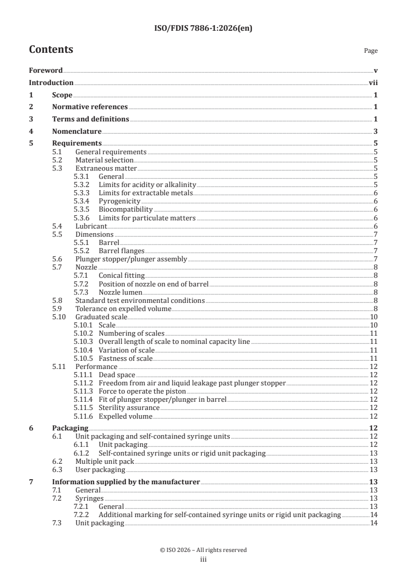
ISO/FDIS 7886-1 - Sterile hypodermic syringes for single use — Part 1: Syringes for manual use

REDLINE ISO/FDIS 7886-1 - Sterile hypodermic syringes for single use — Part 1: Syringes for manual use
ISO/FDIS 7886-1 - Seringues hypodermiques stériles, non réutilisables — Partie 1: Seringues pour utilisation manuelle
ISO/FDIS 7886-1 is an ISO document for sterile hypodermic syringes for single use, Part 1: syringes for manual use. It specifies design requirements and test methods for empty syringes, with or without needle, intended for end-user filling and use mainly in humans. The document is aimed at verifying syringe design, packaging, and marking, not at lot release.
What does ISO/FDIS 7886-1 specify?
ISO/FDIS 7886-1 specifies the requirements and test methods for empty sterile single-use hypodermic syringes made of plastic or other materials, for withdrawal and injection after filling by the end-user. It also sets packaging and manufacturer-information rules that help keep the syringe sterile and usable at the point of care.
The scope excludes insulin syringes, single-use glass syringes, syringes for power-driven syringe pumps, manufacturer pre-filled syringes, and syringes meant to be stored after filling. Hypodermic syringes without a needle are intended to be used with hypodermic needles specified in ISO 7864.
Clauses 1 to 7 cover scope, normative references, terms and definitions, nomenclature, requirements, packaging, and information supplied by the manufacturer. Annexes A to I provide the supporting test methods and sample-preparation steps.
| Annex | What it covers |
|---|---|
| A | Preparation of extracts for chemical checks |
| B | Air leakage past the plunger stopper during withdrawal, and separation of plunger stopper and plunger |
| C | Force needed to operate the piston |
| D | Dead space determination |
| E | Liquid leakage at the plunger stopper under compression |
| F | Silicone quantity test method |
| G | Sample preparation for particulate determination |
| H | Expelled volume determination |
| I | Scale fastness determination |
What are the key requirements of ISO/FDIS 7886-1?
ISO/FDIS 7886-1 is a performance-oriented standard. It focuses on safety, dose accuracy, cleanability, sterility maintenance, and readable markings, while leaving room for manufacturers to choose materials and design details.
Design and materials
Clause 5.1 treats the general requirements as design inputs. Syringes must be free from defects that could affect appearance, safety, or performance, and any integrated or add-on sharps protection must comply with ISO 23908.
Barrel flanges must be large, strong, and shaped for secure handling. Their design is to be supported by risk analysis and usability engineering in accordance with IEC 62366-1, which matters in practice because poor finger grips can affect control during injection.
Clause 5.2 leaves material choice open, but requires materials suitable for the intended use and readable markings on the barrel. In practice, the manufacturer has to select materials and print quality that support safe use rather than relying on a prescribed material list.
Cleanliness, biocompatibility, and lubricants
Clause 5.3 addresses cleanliness and chemical/biological suitability. The syringe surfaces that contact the fluid must be free from extraneous matter, extractables are checked for acidity/alkalinity and metals, pyrogenicity is addressed through recognized endotoxin approaches, and biocompatibility is evaluated in accordance with ISO 10993-1.
Clause 5.3 also sets particulate-contamination expectations and links sample preparation to Annex G. For manufacturers, this means particulate control is part of process validation and change control, not just final inspection.
Clause 5.4 limits lubricants on the interior surface and in the polymer formulation. Annex F gives a method for measuring silicone quantity. This matters because excess lubricant can affect readability, contribute to visible particles, or interfere with clean fluid delivery.
Functional performance
Clauses 5.6 and 5.7 cover the piston, plunger stopper, and nozzle. The plunger stopper must remain attached during the withdrawal test in Annex B, the plunger must be long enough to traverse the barrel, and the syringe should not roll excessively when placed on a slope.
The nozzle fitting must conform to ISO 80369-7, and the nozzle layout depends on nominal capacity. For smaller syringes, the nozzle position and lumen size are controlled so the syringe remains compatible and practical to use.
Clauses 5.8 to 5.11 bring the key performance checks together. Table 1 links nominal capacity to expelled-volume tolerance, dead space, scale layout, and test forces; Table 2 defines dead-space classes for smaller syringes; Annex D measures dead space; Annex E checks leakage under compression; Annex C covers piston-operating force; Annex H determines expelled volume; and Annex I checks that scale markings remain legible after handling.
Clause 5.11 also requires a validated sterilization process and packaging that preserves sterility through shelf-life and shipping validation. In practice, the manufacturer must show that the sterile barrier system still works after transport and storage.
Packaging and marking
Clause 6 covers unit packaging, multiple unit packs, user packaging, and the newer rigid unit packaging category. The packaging must protect the syringe, maintain sterility, and make any opening obvious.
Clause 7 defines the information supplied by the manufacturer. Marking includes single-use identification, sterility, batch or lot identification, contents, expiry information, and, where applicable, LDS or ULDS identification. For the user, this is what supports correct selection, traceability, and safe point-of-use handling.
What terms does ISO/FDIS 7886-1 define?
- Dead space - The liquid remaining in the syringe after the plunger stopper is fully depressed during normal use.
- Nominal capacity - The capacity designated by the manufacturer, such as the syringe size the product is sold and specified for.
- Total graduated capacity - The capacity shown by the furthest graduation line, which may equal or exceed the nominal capacity.
- Fiducial line - The leading edge on the plunger stopper that aligns with the zero mark when the piston is fully inserted.
- Plunger stopper - The component at the leading end of the plunger that seals the open end of the barrel.
- Self-contained syringe - A syringe fitted with protective end caps that help maintain sterility of the interior.
- Rigid unit packaging - A rigid sleeve with end cap(s) that maintains sterility until the package is opened.
Who uses ISO/FDIS 7886-1?
ISO/FDIS 7886-1 is used by syringe manufacturers, packaging engineers, sterilization teams, and laboratory staff who verify design and performance. Quality managers and regulatory teams use it to define acceptance criteria for cleanliness, dose delivery, marking, and sterile-barrier performance.
It is also relevant to buyers and specifiers of medical devices, especially when they need to distinguish between manual-use syringes, insulin syringes, prefilled products, and syringes intended for later storage after filling. Healthcare product developers use it when designing syringe systems for human use.
What changed in ISO/FDIS 7886-1 from the previous edition?
ISO/FDIS 7886-1 is the third edition and it cancels and replaces ISO 7886-1:2017.
The main changes stated in the document are:
- Requirements are reorganized into a single Clause 5 with clearer subclauses.
- Particulate matter control is tightened and supported by a new Annex G.
- The expelled-volume structure is revised, including a new low-fill tolerance tier and a new Annex H method.
- Smaller syringes now use tiered dead-space classes, with LDS and ULDS identification on packaging where applicable.
- Inspection conditions for marking legibility and extraneous-matter checks are defined.
- Sterility assurance and scale fastness are now formally addressed, with Annex I for scale marking durability.
- Rigid unit packaging is added as a packaging category.
- Normative references are updated, including IEC 62366-1, ISO 3696, and ISO 15223-1.
Which standards are used with ISO/FDIS 7886-1?
| Standard | What it contributes |
|---|---|
| ISO 3696 | Water quality for analytical and test procedures |
| ISO 10993-1 | Biological evaluation within a risk-management process |
| ISO 23908 | Requirements for sharps protection mechanisms |
| IEC 62366-1 | Usability engineering for medical devices |
| ISO 80369-7 | Compatibility of the nozzle conical fitting |
| ISO 7864 | Needle compatibility for syringes without a needle |
| ISO 8537 | The excluded insulin-syringe family for comparison |
| ISO 15223-1 | Symbols used for single-use, sterile, expiry, and damage warnings |
| ISO 14971 | Risk management used where the standard calls for risk assessment |
| ISO/TR 19244 | Guidance on transition periods for ISO/TC 84 standards |
What does the ISO/FDIS 7886-1 document contain?
ISO/FDIS 7886-1 contains a component nomenclature figure, performance tables, packaging and marking rules, and a set of supporting test annexes. The tables connect syringe capacity with volume tolerance, dead space, scale layout, and test forces, so they are used directly for design verification and product specification.
The annexes provide the practical methods behind the requirements. Some are normative and therefore part of the compliance path, while others are informative and give suggested ways to test force or silicone quantity.
The document is structured so manufacturers can verify cleanliness, leakage, dose delivery, scale durability, and sterility maintenance using defined procedures. It is therefore used in product development, type testing, and manufacturing validation for sterile manual-use hypodermic syringes.
Relations
- Effective Date
- 12-Feb-2026
- Consolidates
ISO 4917-4:2024 - Design of nuclear power plants against seismic events — Part 4: Components - Effective Date
- 17-Aug-2024
- Revises
ISO 7886-1:2017 - Sterile hypodermic syringes for single use — Part 1: Syringes for manual use - Effective Date
- 06-Jun-2022
Buy Documents
ISO/FDIS 7886-1 - Sterile hypodermic syringes for single use — Part 1: Syringes for manual use
REDLINE ISO/FDIS 7886-1 - Sterile hypodermic syringes for single use — Part 1: Syringes for manual use
ISO/FDIS 7886-1 - Seringues hypodermiques stériles, non réutilisables — Partie 1: Seringues pour utilisation manuelle
Get Certified
Connect with accredited certification bodies for this standard

BSI Group
BSI (British Standards Institution) is the business standards company that helps organizations make excellence a habit.

TÜV Rheinland
TÜV Rheinland is a leading international provider of technical services.

TÜV SÜD
TÜV SÜD is a trusted partner of choice for safety, security and sustainability solutions.
Sponsored listings
Frequently Asked Questions
ISO/FDIS 7886-1 is a draft published by the International Organization for Standardization (ISO). Its full title is "Sterile hypodermic syringes for single use — Part 1: Syringes for manual use". This standard covers: ISO 7886-1:2017 specifies requirements and test methods for verifying the design of empty sterile single-use hypodermic syringes, with or without needle, made of plastic or other materials and intended for the aspiration and injection of fluids after filling by the end-users. This document does not provide requirements for lot release. The syringes are primarily for use in humans. Sterile syringes specified in this document are intended for use immediately after filling and are not intended to contain the medicament for extended periods of time. It excludes syringes for use with insulin (see ISO 8537), single-use syringes made of glass, syringes for use with power-driven syringe pumps, syringes pre-filled by the manufacturer, and syringes intended to be stored after filling (e.g. in a kit for filling by a pharmacist). Hypodermic syringes without a needle specified in this document are intended for use with hypodermic needles specified in ISO 7864.
ISO 7886-1:2017 specifies requirements and test methods for verifying the design of empty sterile single-use hypodermic syringes, with or without needle, made of plastic or other materials and intended for the aspiration and injection of fluids after filling by the end-users. This document does not provide requirements for lot release. The syringes are primarily for use in humans. Sterile syringes specified in this document are intended for use immediately after filling and are not intended to contain the medicament for extended periods of time. It excludes syringes for use with insulin (see ISO 8537), single-use syringes made of glass, syringes for use with power-driven syringe pumps, syringes pre-filled by the manufacturer, and syringes intended to be stored after filling (e.g. in a kit for filling by a pharmacist). Hypodermic syringes without a needle specified in this document are intended for use with hypodermic needles specified in ISO 7864.
ISO/FDIS 7886-1 is classified under the following ICS (International Classification for Standards) categories: 11.040.25 - Syringes, needles an catheters. The ICS classification helps identify the subject area and facilitates finding related standards.
ISO/FDIS 7886-1 has the following relationships with other standards: It is inter standard links to FprEN ISO 7886-1, ISO 4917-4:2024, ISO 7886-1:2017. Understanding these relationships helps ensure you are using the most current and applicable version of the standard.
ISO/FDIS 7886-1 is available in PDF format for immediate download after purchase. The document can be added to your cart and obtained through the secure checkout process. Digital delivery ensures instant access to the complete standard document.
Standards Content (Sample)
FINAL DRAFT
International
Standard
ISO/TC 84
Sterile hypodermic syringes for
Secretariat: DS
single use —
Voting begins on:
2026-10-16
Part 1:
Syringes for manual use
Voting terminates on:
2026-12-11
Seringues hypodermiques stériles, non réutilisables —
Partie 1: Seringues pour utilisation manuelle
RECIPIENTS OF THIS DRAFT ARE INVITED TO SUBMIT,
WITH THEIR COMMENTS, NOTIFICATION OF ANY
RELEVANT PATENT RIGHTS OF WHICH THEY ARE AWARE
AND TO PROVIDE SUPPOR TING DOCUMENTATION.
IN ADDITION TO THEIR EVALUATION AS
BEING ACCEPTABLE FOR INDUSTRIAL, TECHNO-
ISO/CEN PARALLEL PROCESSING LOGICAL, COMMERCIAL AND USER PURPOSES, DRAFT
INTERNATIONAL STANDARDS MAY ON OCCASION HAVE
TO BE CONSIDERED IN THE LIGHT OF THEIR POTENTIAL
TO BECOME STAN DARDS TO WHICH REFERENCE MAY BE
MADE IN NATIONAL REGULATIONS.
Reference number
FINAL DRAFT
International
Standard
ISO/TC 84
Sterile hypodermic syringes for
Secretariat: DS
single use —
Voting begins on:
Part 1:
Syringes for manual use
Voting terminates on:
Seringues hypodermiques stériles, non réutilisables —
Partie 1: Seringues pour utilisation manuelle
© ISO 2026
All rights reserved.
RECIPIENTS OF THIS DRAFT ARE INVITED TO SUBMIT,
WITH THEIR COMMENTS, NOTIFICATION OF ANY
This ISO publication is protected by copyright and is owned by ISO and/or its licensors.
RELEVANT PATENT RIGHTS OF WHICH THEY ARE AWARE
The content of this ISO publication is provided under licence, not sold. Use is subject to the applicable licence terms issued by ISO,
AND TO PROVIDE SUPPOR TING DOCUMENTATION.
an ISO member body, or an authorized third-party distributor.
IN ADDITION TO THEIR EVALUATION AS
BEING ACCEPTABLE FOR INDUSTRIAL, TECHNO-
Except as required for implementation or expressly permitted by a separate licence, no part of this ISO publication may be
ISO/CEN PARALLEL PROCESSING
LOGICAL, COMMERCIAL AND USER PURPOSES, DRAFT
reproduced, distributed, modified, used, or made available in any form or by any means – electronic or mechanical, including
INTERNATIONAL STANDARDS MAY ON OCCASION HAVE
photocopying, scanning, recording, or posting on internal or external digital platforms. TO BE CONSIDERED IN THE LIGHT OF THEIR POTENTIAL
TO BECOME STAN DARDS TO WHICH REFERENCE MAY BE
Any use beyond the scope of the granted rights is prohibited and may result in legal action.
MADE IN NATIONAL REGULATIONS.
ISO copyright office
CP 401 • CH-1214 Vernier, Geneva
Phone: +41 22 749 01 11
Email: copyright@iso.org
Website: www.iso.org
Published in Switzerland
Reference number
ii
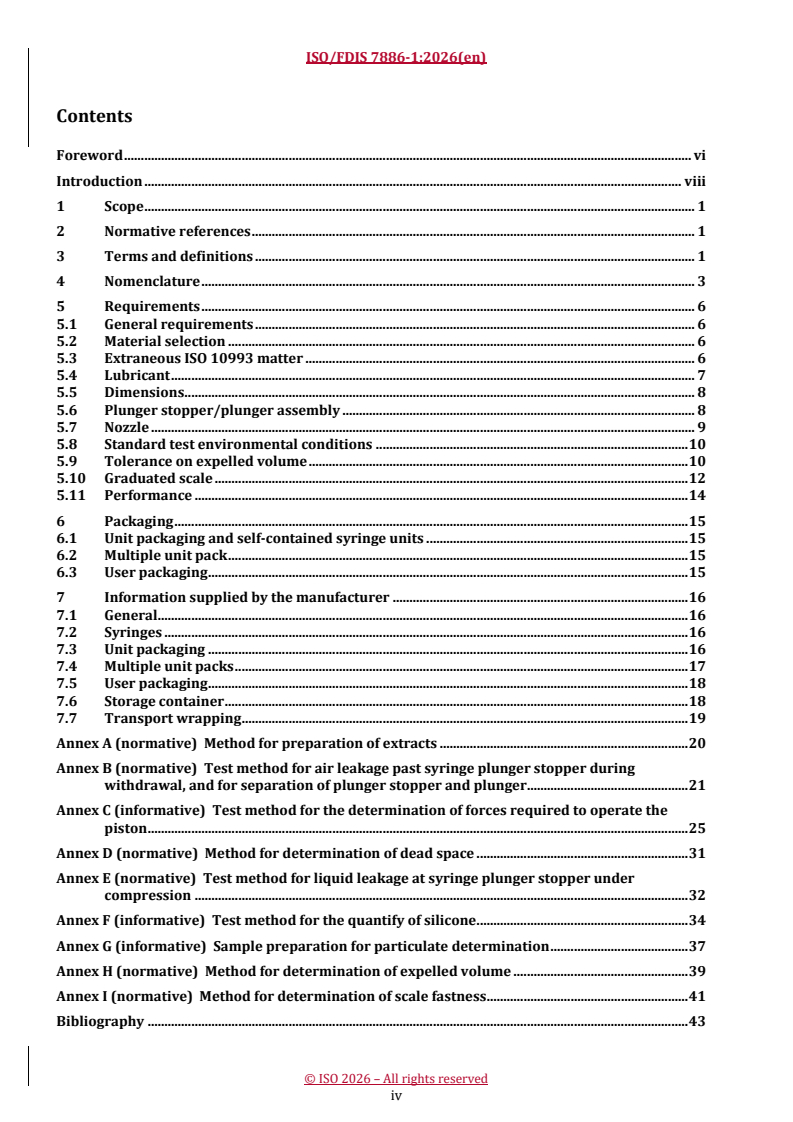
Contents Page
Foreword .v
Introduction .vii
1 Scope . 1
2 Normative references . 1
3 Terms and definitions . 1
4 Nomenclature . 3
5 Requirements . 5
5.1 General requirements .5
5.2 Material selection .5
5.3 Extraneous matter .5
5.3.1 General .5
5.3.2 Limits for acidity or alkalinity .5
5.3.3 Limits for extractable metals .6
5.3.4 Pyrogenicity .6
5.3.5 Biocompatibility .6
5.3.6 Limits for particulate matters .6
5.4 Lubricant .6
5.5 Dimensions .7
5.5.1 Barrel .7
5.5.2 Barrel flanges .7
5.6 Plunger stopper/plunger assembly .7
5.7 Nozzle .8
5.7.1 Conical fitting .8
5.7.2 Position of nozzle on end of barrel .8
5.7.3 Nozzle lumen . .8
5.8 Standard test environmental conditions .8
5.9 Tolerance on expelled volume .8
5.10 Graduated scale . .10
5.10.1 Scale .10
5.10.2 Numbering of scales .11
5.10.3 Overall length of scale to nominal capacity line .11
5.10.4 Variation of scale .11
5.10.5 Fastness of scale.11
5.11 Performance . 12
5.11.1 Dead space . 12
5.11.2 Freedom from air and liquid leakage past plunger stopper . 12
5.11.3 Force to operate the piston . 12
5.11.4 Fit of plunger stopper/plunger in barrel . 12
5.11.5 Sterility assurance . 12
5.11.6 Expelled volume . 12
6 Packaging.12
6.1 Unit packaging and self-contained syringe units . 12
6.1.1 Unit packaging . 12
6.1.2 Self-contained syringe units or rigid unit packaging . 13
6.2 Multiple unit pack . 13
6.3 User packaging . 13
7 Information supplied by the manufacturer .13
7.1 General . 13
7.2 Syringes . 13
7.2.1 General . 13
7.2.2 Additional marking for self-contained syringe units or rigid unit packaging .14
7.3 Unit packaging .14
iii
7.4 Multiple unit packs .14
7.4.1 General .14
7.4.2 Multiple unit packs with self-contained syringes . . 15
7.5 User packaging . 15
7.6 Storage container . 15
7.7 Transport wrapping . .16
Annex A (normative) Method for preparation of extracts . 17
Annex B (normative) Test method for air leakage past syringe plunger stopper during
withdrawal, and for separation of plunger stopper and plunger .18
Annex C (informative) Test method for the determination of forces required to operate the
piston .21
Annex D (normative) Method for determination of dead space .24
Annex E (normative) Test method for liquid leakage at syringe plunger stopper under
compression .25
Annex F (informative) Test method for the quantify of silicone .27
Annex G (informative) Sample preparation for particulate determination .30
Annex H (normative) Method for determination of expelled volume .32
Annex I (normative) Method for determination of scale fastness .33
Bibliography .35
iv
Foreword
ISO (the International Organization for Standardization) is a worldwide federation of national standards
bodies (ISO member bodies). The work of preparing International Standards is normally carried out through
ISO technical committees. Each member body interested in a subject for which a technical committee
has been established has the right to be represented on that committee. International organizations,
governmental and non-governmental, in liaison with ISO, also take part in the work. ISO collaborates closely
with the International Electrotechnical Commission (IEC) on all matters of electrotechnical standardization.
The procedures used to develop this document and those intended for its further maintenance are described
in the ISO/IEC Directives, Part 1. In particular, the different approval criteria needed for the different types
of ISO documents should be noted. This document was drafted in accordance with the editorial rules of the
ISO/IEC Directives, Part 2 (see www.iso.org/directives).
ISO draws attention to the possibility that the implementation of this document may involve the use of (a)
patent(s). ISO takes no position concerning the evidence, validity or applicability of any claimed patent
rights in respect thereof. As of the date of publication of this document, ISO had not received notice of (a)
patent(s) which may be required to implement this document. However, implementers are cautioned that
this may not represent the latest information, which may be obtained from the patent database available at
www.iso.org/patents. ISO shall not be held responsible for identifying any or all such patent rights.
Any trade name used in this document is information given for the convenience of users and does not
constitute an endorsement.
For an explanation of the voluntary nature of standards, the meaning of ISO specific terms and expressions
related to conformity assessment, as well as information about ISO’s adherence to the World Trade
Organization (WTO) principles in the Technical Barriers to Trade (TBT), see www.iso.org/iso/foreword.html.
This document was prepared by Technical Committee ISO/TC 84, Devices for administration of medicinal
products and catheters, in collaboration with the European Committee for Standardization (CEN) Technical
Committee CEN/TC 205, Non-active medical devices, in accordance with the Agreement on technical
cooperation between ISO and CEN (Vienna Agreement).
This third edition cancels and replaces the second edition (ISO 7886-1:2017), which has been technically
revised.
The main changes are as follows:
― Restructured requirements: all requirements are consolidated into a single Clause 5, with new formal
subclauses added for material selection, pyrogenicity, biocompatibility, particulate matter, sterility
assurance, scale fastness, and expelled volume.
― New particulate matter limits: explicit sub-visible particle limits are established (≤3 000 particles
≥10 µm; ≤300 particles ≥25 µm per syringe), supported by a new Annex G for sample preparation.
― Revised volume tolerance structure: a third tolerance tier is added for volumes less than 20 % of nominal
capacity (±10 % of expelled volume), and the terminology shifts from “graduated capacity” to “expelled
volume”, with a new normative gravimetric test method (Annex H).
― Tiered dead space categories for small syringes: for syringes <5 ml, three dead space tiers are introduced ‒
RDS (≤0,070 ml), LDS (≤0,025 ml), and ULDS (≤0,015 ml) ‒ replacing the single maximum value in the
2017 edition, with required labeling of LDS/ULDS on packaging.
― Defined inspection conditions: specific illuminance and viewing distance requirements are now
specified for both marking legibility (<100 lx, 30 to 70 cm) and extraneous matter inspection (≥500 lx,
30 to 70 cm).
−6
― New sterility assurance and scale fastness requirements: a formal SAL of 10 with shelf-life and shipping
validation is now required, and a new normative Annex I defines a tape adhesion and solvent resistance
test for scale markings.
v
― Rigid unit packaging added: a new packaging category, rigid unit packaging [rigid sleeve with end cap(s)]
is introduced with corresponding labelling requirements throughout Clause 7.
― Updated normative references: IEC 62366-1 (usability engineering) is elevated to normative status,
ISO 3696 is added to specify water purity grade 3 for test reagents, and ISO 15223-1.
A list of all parts in the ISO 7886 series can be found on the ISO website.
Any feedback or questions on this document should be directed to the user’s national standards body. A
complete listing of these bodies can be found at www.iso.org/members.html.
vi
Introduction
The ISO 7886 series covers hypodermic syringes primarily intended for human use and provides
performance and testing requirements. It permits broader variation in design so as not to limit innovation
and methods of packaging. Its appearance and layout are consistent with other related standards which are
designed to be more performance-based compared to design-prescriptive.
General requirements as design guidelines for manufacturers are introduced in this document. Several
limits for requirements which are historic based but confirmed in practice for many years have been kept.
Materials to be used for the construction and lubrication of sterile syringes for single use are not specified as
their selection will depend to some extent upon the design, process of manufacture and sterilization method
employed by individual manufacturers. The materials of the syringe should be compatible with injection
fluids. If this is not the case, the attention of the user should be drawn to the exception by labelling on unit
packaging. It is not practicable to specify a universally acceptable test method for incompatibility, as the
only conclusive test is that an individual specific injection fluid is compatible with a specific syringe.
Manufacturers of pharmaceuticals use solvents in injectable preparations. Such solvents should be tested by
the manufacturer of the injectable preparation for any possible incompatibility with the materials frequently
used in syringe construction. If an incompatibility is identified, the injection fluid should be suitably labelled.
The impossibility of testing any one injection fluid with all available syringes is recognized and it is strongly
recommended that regulatory authorities and relevant trade associations recognize the problem and take
appropriate measures to assist manufacturers of injectable preparations.
Syringes should be manufactured and sterilized in accordance with recognized national or international
codes of good manufacturing practice for medical devices.
The sampling plans for inspection selected for the ISO 7886 series are intended to verify the design at a high
confidence level. The sampling plans for inspection do not replace the more general manufacturing quality
systems requirements that appear in quality management systems, e.g. ISO 9001 or ISO 13485.
Manufacturers are expected to follow a risk-based approach and employ usability engineering during the
design, development and manufacture of syringes.
Guidance on transition periods for implementing the requirements of the ISO 7886 series is given in
ISO/TR 19244.
vii
FINAL DRAFT International Standard ISO/FDIS 7886-1:2026(en)
Sterile hypodermic syringes for single use —
Part 1:
Syringes for manual use
1 Scope
This document specifies requirements and test methods for verifying the design of empty sterile single-
use hypodermic syringes, with or without needle, made of plastic or other materials and intended for the
withdrawal and injection of fluids after filling by the end-users. Sterile syringes specified in this document
are intended for use immediately after filling and are not intended to contain the medicament for extended
periods of time.
This document does not provide requirements for lot release. The syringes are primarily for use in humans.
It excludes syringes for use with insulin (see ISO 8537), single-use syringes made of glass, syringes for use
with power-driven syringe pumps, syringes pre-filled by the manufacturer, and syringes intended to be
stored after filling (e.g. in a kit for filling by a pharmacist).
Hypodermic syringes without a needle specified in this document are intended for use with hypodermic
needles specified in ISO 7864.
2 Normative references
The following documents are referred to in the text in such a way that some or all of their content constitutes
requirements of this document. For dated references, only the edition cited applies. For undated references,
the latest edition of the referenced document (including any amendments) applies.
ISO 3696, Water for analytical laboratory use — Specification and test methods
ISO 10993-1, Biological evaluation of medical devices — Part 1: Requirements and general principles for the
evaluation of biological safety within a risk management process
ISO 23908, Sharps injury protection — Sharps protection mechanisms for single-use needles, introducers for
catheters and needles used for blood testing, monitoring, sampling and medical substance administration —
Requirements and test methods
IEC 62366-1, Medical devices — Part 1: Application of usability engineering to medical devices
ISO 80369-7, Small-bore connectors for liquids and gases in healthcare applications — Part 7: Connectors for
intravascular or hypodermic applications
3 Terms and definitions
For the purposes of this document, the following terms and definitions apply.
ISO and IEC maintain terminology databases for use in standardization at the following addresses:
— ISO Online browsing platform: available at https:// www .iso .org/ obp
— IEC Electropedia: available at https:// www .electropedia .org/
3.1
barrel flanges
flanges that protrude from the barrel (also referred to as finger grips) to provide the user an ergonomic
means of gripping the syringe during injection
3.2
dead space
volume of liquid left in the syringe when the plunger stopper (3.12) is fully depressed during normal use
3.3
fiducial line
leading edge on the plunger stopper (3.12) that is in contact with and perpendicular to the syringe barrel and
aligns with the zero marking on the syringe barrel when the piston (3.10) is fully inserted
3.4
graduated capacity
volume markings printed on the syringe barrel and the maximum amount of liquid the syringe can accurately
measure and hold
3.5
multiple unit pack
multiple syringes packaged with a single seal that maintains the sterility of the product
3.6
needle cap
needle shield
sheath intended to physically protect the needle prior to use
3.7
nominal capacity
capacity of the syringe as designated by the manufacturer
EXAMPLE 1 ml, 5 ml, 50 ml
3.8
nozzle cap
sheath intended to physically protect the nozzle prior to use
3.9
nozzle lumen
internal space or cavity within the syringe nozzle through which the fluid passes, extending from the internal
end of the syringe barrel where the nozzle begins and continuing through to the tip of the nozzle
3.10
piston
assembled component of plunger (3.11) and plunger stopper (3.12)
3.11
plunger
device component which advances the plunger stopper (3.12) to deliver the medicinal product
3.12
plunger stopper
component connected to the leading end of the plunger (3.11) and that seals the open end of the syringe
barrel
3.13
rigid unit packaging
rigid sleeve with end cap(s), which maintains the sterility of the contents until the package is opened
3.14
self-contained syringe
syringe with protective end caps [i.e. plunger cap, and nozzle cap (3.8) or needle cap (3.6)] intended to
maintain the sterility of the interior of the syringe
3.15
total graduated capacity
capacity of the syringe at the graduation line furthest from the zero graduation line
Note 1 to entry: The total graduated capacity may be equal to, or greater than, the nominal capacity.
3.16
unit packaging
packaging which has direct contact with the device and maintains the sterility of the product
3.17
user packaging
packaging designed to contain one or more unit packages or self-contained syringe (3.14) units
Note 1 to entry: Self-contained syringe units can be packed in multiple unit packs (3.5).
4 Nomenclature
The nomenclature for the components of hypodermic syringes for single use is shown in Figure 1.
Key
1 needle cap or needle shield (if used)
2 nozzle cap
3 nozzle lumen
4 nozzle
5 barrel
6 plunger stopper (3-piece only)
7 seals
8 plunger
9 push-button
10 plunger cap
11 barrel flanges (finger grips)
12 fiducial line
13 nominal capacity
14 graduation lines
15 zero line
16 needle tube
17 hub
18 piston
NOTE The figure is intended to be illustrative of the components of a syringe. The plunger stopper/plunger
assembly can be of integral construction and can incorporate more than one seal.
Figure 1 — Schematic representation of hypodermic syringes for single use
5 Requirements
5.1 General requirements
The general requirements are considered to be design inputs for manufacturers.
Syringes shall be free from defects affecting appearance, safety and performance for their intended use.
Syringes with integrated or add-on sharps protection shall also conform with ISO 23908.
The syringe’s barrel flanges shall be of adequate size, shape and strength for the intended purpose. The
design specifications for the barrel flanges shall be determined through risk analysis and confirmed through
the application of usability engineering in accordance with IEC 62366-1.
5.2 Material selection
The materials shall satisfy the requirement for freedom from regarding acceptable levels of pyrogens and
toxins appropriate to the intended use of the product.
Materials used in the construction of the wall of the syringe barrel shall have sufficient clarity to enable the
user to read dosages with normal or corrected to normal vision and environmental lighting conditions of
< 100 lx, and from a reading distance of between 30 cm and 70 cm.
NOTE 1 The legibility of markings inspection is supposed to ensure that users of needle-based injection systems
(NIS) are able to read the markings under real life conditions (e.g. limited light intensity).
NOTE 2 The lighting levels chosen for this subclause were the lowest levels listed in ISO/CIE 8995-1 and depict
ambient lighting levels that are likely to be seen in private homes or in the entrance halls, rest rooms or corridors of
public spaces (e.g. hotels or hospitals). This level is chosen as representative of what patients – users of these syringes
- can be expected to encounter as they look to read markings on these devices. Other lighting levels can be appropriate
based on the intended use of the syringe.
The document does not specify materials to be used for the construction and lubrication of sterile syringes
with or without needles for single use, because their selection will depend, to some extent, upon the
manufacturers specific syringe design, process of manufacture and sterilization method.
5.3 Extraneous matter
5.3.1 General
The surfaces of the syringe that come in contact with injection fluids during normal use shall be free from
particles and extraneous matter when inspected without magnification, with normal or corrected to normal
vision under an illuminance of minimum 500 lx, and from a reading distance of between 30 cm and 70 cm.
NOTE 1 Conformity with this requirement is determined through inspection by an individual with normal vision
(or corrected-to-normal vision), without magnification.
NOTE 2 The lighting levels chosen for this subclause were the lighting levels listed in ISO/CIE 8995-1 expected to be
seen in inspection areas in the chemical, plastics or rubber industry.
5.3.2 Limits for acidity or alkalinity
Exposure of distilled water to the finished syringe product shall not change its pH value by more than one
unit.
The requirement shall be demonstrated by preparing the solutions specified in Annex A. The results shall
show that the pH value of the syringe assessment fluid is within one pH unit of the pH value of the control
fluid.
The pH value of both solutions can be determined with a laboratory potentiometric pH meter using a general
purpose electrode.
5.3.3 Limits for extractable metals
Exposure of distilled water to the finished syringe product shall not change its content of metals by more
than a combined total of 5 mg/kg of lead, tin, zinc and iron; the cadmium content shall be less than 0,1 mg/
kg.
This requirement shall be demonstrated by preparing the solutions specified in Annex A and testing
them using a recognized micro-analytical method, for example, by an atomic absorption method or by an
inductively coupled plasma mass spectrometry method (ICP).
This test shall be performed whenever there is any change in construction material.
5.3.4 Pyrogenicity
Pyrogenicity mediated by endotoxin can be measured by an endotoxin-specific LAL (Limulus Amebocyte
Lysate) test, referring to the specific test given in AAMI/ST72 as suggested by ISO 10993-11:2017, Annex G.
Other references to this test can be found in USP <85> and/or EU pharmacopeia.
Extraction method and testing are specified in regional and national pharmacopoeias:
— for extraction method, see USP <161>;
— for testing, see Ph.Eur., 2.6.14, method c), USP <85> and JP 4.01.
5.3.5 Biocompatibility
Biocompatibility shall be evaluated in accordance with ISO 10993-1. Other relevant parts of the ISO 10993
series can be applied when appropriate to the intended clinical use and contact characteristics of the syringe.
5.3.6 Limits for particulate matters
Sterilized syringes shall be manufactured by processes that minimize the risk of particulate contamination
of the intended content.
The particle-related specifications given in pharmacopoeias (e.g. Ph.Eur., USP, JP) do not apply to empty
containers but, to show a certain cleanliness level, specifications have been set.
For sub-visible particles, the following applies:
— particles ≥10 µm: 3 000 max. per syringe;
— particles ≥25 µm: 300 max. per syringe.
NOTE These limits have been derived from the USP <788> (small volume parenterals) limit values for filled
containers with a nominal volume of less than 100 ml. The limits, which is 50 % of the USP <788>, have been chosen
based on historical proven capability using the light obscuration method as given in Annex G.
5.4 Lubricant
For lubricants applied to interior surface of the syringe, the quantity of lubricant applied shall not exceed
0,25 mg/cm of the interior surface area of the syringe in contact with the injection fluid.
The amount and distribution of lubricant applied should be optimized to minimize lubricant visibility.
NOTE 1 An acceptable lubricant is silicone complying with a national or the European pharmacopoeia and
ISO 10993-1.
For lubricants incorporated in the polymer formulation, the quantity of lubricant shall not exceed 0,6 %
(weight fraction) of the mass of the component, but attention is drawn to the fact that some national
regulations can specify a lower maximum concentration.
NOTE 2 If a lubricant is incorporated in the polymer formulation, visible particles can become apparent when the
lubricant blooms to the surface of the syringe barrel and the plunger stopper scrapes it off.
NOTE 3 Example of acceptable lubricants incorporated in the polymer formulation are fatty acid amides of erucic
and/or oleic acids conforming with ISO 10993-1.
NOTE 4 See Annex F for a test method for the quantity of silicone oil.
5.5 Dimensions
5.5.1 Barrel
Maximum capacity shall be determined by risk assessment with consideration of, for example, removal of
air bubbles or risk of overdose.
5.5.2 Barrel flanges
The open end of the barrel shall be provided with barrel flanges. Barrel flanges shall be of adequate size,
shape and strength for the intended purpose and shall enable the syringe to be held securely during use.
5.6 Plunger stopper/plunger assembly
When tested in accordance with Annex B, the plunger stopper shall not become detached from the plunger.
The plunger shall be of a length adequate to allow the plunger stopper to traverse the full length of the
barrel. By risk assessment, the manufacturer shall set and verify a specification for an increased force for
removal of the piston completely from the barrel.
The projection of the plunger and the configuration of the push-button should be such as to allow the
plunger to be operated without difficulty. When the fiducial line of the plunger stopper coincides with the
zero graduation line, the minimum length of the plunger from the surface of the barrel flanges nearer to the
push-button, as shown in Figure 2, shall be at least 8 mm.
Key
1 minimum 8 mm
Figure 2 — Minimum length between barrel flanges and plunger push-button
The syringe design, such as barrel flanges, shall be such that the syringe will not roll more than 180° when it
is placed on a flat surface at an angle of 10° to the horizontal. The barrel flanges shall be free from flash and
sharp edges.
Finger grip configurations that do not conform to these requirements are recommended to be assessed for
risk according to ISO 14971 and for usability according to IEC 62366-1.
5.7 Nozzle
5.7.1 Conical fitting
The male conical fitting of the syringe nozzle shall be in accordance with ISO 80369-7.
If the syringe has a locking fitting, it shall be in accordance with ISO 80369-7.
5.7.2 Position of nozzle on end of barrel
5.7.2.1 On syringes of nominal capacity of less than 5 ml, the syringe nozzle shall be situated centrally, i.e.
it shall be coaxial with the barrel.
5.7.2.2 On syringes of nominal capacity of 5 ml and greater, the syringe nozzle shall be situated either
centrally or eccentrically.
5.7.2.3 If the syringe nozzle is eccentric, its axis shall be vertically below the axis of the barrel when the
syringe is lying on a flat surface with the scale uppermost. The distance between the axis of the nozzle and
the nearest point on the internal surface of the bore of the barrel shall be not greater than 4,5 mm.
5.7.3 Nozzle lumen
The nozzle lumen shall have a diameter of not less than 1,2 mm.
5.8 Standard test environmental conditions
Unless otherwise specified, measurements shall be performed under the following atmospheric conditions:
— temperature between 18 °C and 28 °C;
— relative humidity between 25 % RH and 75 % RH.
Testing shall be performed after samples have been stored under these conditions for at least 4 h.
5.9 Tolerance on expelled volume
The tolerances on the expelled volume at each graduation shall be as given in Table 1.
Table 1 — Capacity tolerance, dead space, scale dimensions and test forces
Nominal Tolerance on expelled volume at any graduation Maximum Minimum Scale Increment Forces and pressures for
capacity of dead space overall length interval between leakage testing
syringe of scale to graduation (see Annex E)
nominal ca- lines to be
V
Less than 20 % Less than half Equal to or greater Side Axial pressure
pacity mark numbered
nominal and more than than half nominal force (gauge)
capacity or equal to 20 % capacity
(±5 %) (±5 %)
nominal capacity
ml ml mm ml ml N kPa
±10 % of ex- ±(1,5 % of V + 2 % ±5 % of
V < 2 0,07 25 0,05 0,1 0,25 300
pelled volume of expelled volume) expelled volume
±10 % of ex- ±(1,5 % of V + 2 % ±5 % of
2 ≤ V < 5 0,07 27 0,2 1 1,0 300
pelled volume of expelled volume) expelled volume
±10 % of ex- ±(1,5 % of V + 1 % ±4 % of
5 ≤ V < 10 0,075 36 0,5 1 2,0 300
pelled volume of expelled volume) expelled volume
±10 % of ex- ±(1,5 % of V + 1 % ±4 % of
10 ≤ V < 20 0,10 44 1,0 5 2,0 300
pelled volume of expelled volume) expelled volume
±(1,5 % of V + 1 % ±4 % of
20 ≤ V < 30 0,15 52 2,0 10 3,0 200
of expelled volume) expelled volume
±(1,5 % of V + 1 % ±4 % of
30 ≤ V < 50 0,17 67 2,0 10 3,0 200
of expelled volume) expelled volume
±(1,5 % of V + 1 % ±4 % of
V ≥ 50 0,20 75 5,0 10 3,0 200
of expelled volume) expelled volume
NOTE 1 Expelled volume means all the liquid ejected with the seal brought to the physical limit that was designed to be coincident with the zero mark of the scale.
NOTE 2 Only for syringes with nominal capacity of Volume (V) less than 5 ml is expressed as RDS = Regular Dead Space, LDS = Low Dead Space and ULDS = Ultra Low Dead Space
as designated in Table 2.
EXAMPLE 1 For a 3 ml syringe, when filled to the 1 ml graduation (less than 1/2 capacity), the required tolerance would be ±(1,5 % × 3 ml + 2 % × 1 ml) = 0,065 ml
EXAMPLE 2 For a 3 ml syringe, when filled to the 2 ml graduation (greater than 1/2 capacity), the required tolerance would be ±(5 % × 2 ml) = 0,100 ml.
EXAMPLE 3 For a 1 ml syringe, when filled to the 0,1 ml graduation (less than 20 % nominal capacity), the required tolerance would be ±10 % = 0,01 ml
Table 2 — Dead space definition for nominal syringes capacity V < 5
Maximum dead space
ml
Regular dead space Low dead space Ultra low dead space
(RDS) (LDS) (ULDS)
0,070 0,025 0,015
5.10 Graduated scale
5.10.1 Scale
5.10.1.1 The syringe shall have either only one scale or more than one identical scale, which shall be
graduated and numbered at least at the intervals given in Table 1. The unit of volume shall be marked on the
barrel.
NOTE The scale interval can be less (finer) than the scale interval given in Table 1.
5.10.1.2 The total graduated capacity may be equal to, or greater than, the nominal capacity. If the scale
is extended beyond the nominal capacity, the extended portion shall be differentiated from the rest of the
scale.
Examples of means of differentiation are the following:
a) encircling the scale number of the nominal capacity line;
b) using smaller scale numbers for the extra graduation lines;
c) using shorter graduation lines for the extra graduation lines;
d) using a broken line for the optional vertical line of the extra scale length.
5.10.1.3 Graduation lines shall be of uniform thickness. They shall lie in planes at right angles to the axis of
the barrel.
5.10.1.4 Graduation lines shall be evenly spaced along the longitudinal axis between the zero graduation
line and the line for the total graduated capacity.
5.10.1.5 When the syringe is held vertically, the ends of all graduation lines of similar length shall be
vertically beneath each other.
The lengths of the short graduation lines on each scale are recommended to be approximately half the length
of the long lines. If different graduation line configurations are used, this can be submitted to usability
evaluation according to IEC
...
Text for ISO/FDIS 7886-1:2026(en)
ISO/TC 84
Date: 2026-06-02
Secretariat: DS
Date: 2026-10-01
Sterile hypodermic syringes for single use — —
Part 1:
Syringes for manual use
Seringues hypodermiques stériles, non réutilisables —
Partie 1: Seringues pour utilisation manuelle
TTTTTThhhhhhiiiiiis drs drs drs drs drs draaaaaafffffftttttt i i i i i is s s s s s susususususubbbbbbmmmmmmiiiiiitttttttttttteeeeeed d d d d d ttttttoooooo aaaaaa ppppppaaaaaarrrrrraaaaaallellellellellellel l l l l l vvvvvvooooootttttteeeeee i i i i i innnnnn IIIIIISSSSSSOOOOOO,,,,,, CCCCCCEEEEEEN.N.N.N.N.N.
© FDIS stage
All rights reserved. Unless otherwise specified,
This ISO publication is protected by copyright and is owned by ISO and/or its licensors.
The content of this ISO publication is provided under licence, not sold. Use is subject to the applicable licence terms issued
by ISO, an ISO member body, or an authorized third-party distributor.
Except as required in the context of its for implementation or expressly permitted by a separate licence, no part of this
ISO publication may be reproduced or utilized otherwise, distributed, modified, used, or made available in any form or
by any means, – electronic or mechanical, including photocopying, scanning, recording, or posting on internal or external
digital platforms.
Any use beyond the internet or an intranet, without prior written permission. Permission can be requested from either
ISO at the address below or ISO’s member body in the countryscope of the requestergranted rights is prohibited and may
result in legal action.
ISO copyright office
CP 401 • Ch. de Blandonnet 8
CH-1214 Vernier, Geneva
Phone: + 41 22 749 01 11
Email: copyright@iso.org
Website: www.iso.org
Published in Switzerland
iii
Contents
Foreword . vi
Introduction . viii
1 Scope . 1
2 Normative references . 1
3 Terms and definitions . 1
4 Nomenclature . 3
5 Requirements . 6
5.1 General requirements . 6
5.2 Material selection . 6
5.3 Extraneous ISO 10993 matter . 6
5.4 Lubricant . 7
5.5 Dimensions . 8
5.6 Plunger stopper/plunger assembly . 8
5.7 Nozzle . 9
5.8 Standard test environmental conditions . 10
5.9 Tolerance on expelled volume . 10
5.10 Graduated scale . 12
5.11 Performance . 14
6 Packaging . 15
6.1 Unit packaging and self-contained syringe units . 15
6.2 Multiple unit pack . 15
6.3 User packaging . 15
7 Information supplied by the manufacturer . 16
7.1 General . 16
7.2 Syringes . 16
7.3 Unit packaging . 16
7.4 Multiple unit packs . 17
7.5 User packaging . 18
7.6 Storage container . 18
7.7 Transport wrapping . 19
Annex A (normative) Method for preparation of extracts . 20
Annex B (normative) Test method for air leakage past syringe plunger stopper during
withdrawal, and for separation of plunger stopper and plunger . 21
Annex C (informative) Test method for the determination of forces required to operate the
piston . 25
Annex D (normative) Method for determination of dead space . 31
Annex E (normative) Test method for liquid leakage at syringe plunger stopper under
compression . 32
Annex F (informative) Test method for the quantify of silicone . 34
Annex G (informative) Sample preparation for particulate determination . 37
Annex H (normative) Method for determination of expelled volume . 39
Annex I (normative) Method for determination of scale fastness . 41
Bibliography . 43
iv
v
Foreword
ISO (the International Organization for Standardization) is a worldwide federation of national standards
bodies (ISO member bodies). The work of preparing International Standards is normally carried out through
ISO technical committees. Each member body interested in a subject for which a technical committee has been
established has the right to be represented on that committee. International organizations, governmental and
non-governmental, in liaison with ISO, also take part in the work. ISO collaborates closely with the
International Electrotechnical Commission (IEC) on all matters of electrotechnical standardization.
The procedures used to develop this document and those intended for its further maintenance are described
in the ISO/IEC Directives, Part 1. In particular, the different approval criteria needed for the different types of
ISO documents should be noted. This document was drafted in accordance with the editorial rules of the
ISO/IEC Directives, Part 2 (see www.iso.org/directives).
ISO draws attention to the possibility that the implementation of this document may involve the use of (a)
patent(s). ISO takes no position concerning the evidence, validity or applicability of any claimed patent rights
in respect thereof. As of the date of publication of this document, ISO [had/had not] received notice of (a)
patent(s) which may be required to implement this document. However, implementers are cautioned that this
may not represent the latest information, which may be obtained from the patent database available at
www.iso.org/patents. ISO shall not be held responsible for identifying any or all such patent rights.
Any trade name used in this document is information given for the convenience of users and does not
constitute an endorsement.
For an explanation of the voluntary nature of standards, the meaning of ISO specific terms and expressions
related to conformity assessment, as well as information about ISO'sISO’s adherence to the World Trade
Organization (WTO) principles in the Technical Barriers to Trade (TBT), see www.iso.org/iso/foreword.html.
This document was prepared by Technical committeeCommittee ISO/TC 84, Devices for administration of
medicinal products and catheters, in collaboration with the European Committee for Standardization (CEN)
Technical Committee CEN/TC 205, Non-active medical devices, in accordance with the Agreement on technical
cooperation between ISO and CEN (Vienna Agreement).
This third edition cancels and replaces the second edition (ISO 7886--1:2017), which has been technically
revised.
The main changes to the previous edition are the followingas follows:
— Restructured requirements: Allall requirements are consolidated into a single Clause 5Section 5,, with new
formal subclauses added for material selection, pyrogenicity, biocompatibility, particulate matter, sterility
assurance, scale fastness, and expelled volume.
— New particulate matter limits: Explicitexplicit sub-visible particle limits are established (≤3 ,000 particles
≥10 µm; ≤300 particles ≥25 µm per syringe), supported by a new Annex Gnormative Annex G for sample
preparation.
— Revised volume tolerance structure: Aa third tolerance tier is added for volumes less than 20 % of nominal
capacity (±10 % of expelled volume), and the terminology shifts from "“graduated capacity"” to "“expelled
volume,"”, with a new normative gravimetric test method (Annex H(Annex H).).
— Tiered dead space categories for small syringes: Forfor syringes <5 ml, three dead space tiers are
introduced — ‒ RDS (≤0.,070 ml), LDS (≤0.,025 ml), and ULDS (≤0.,015 ml) —‒ replacing the single
maximum value in the 2017 edition, with required labeling of LDS/ULDS on packaging.
vi
— Defined inspection conditions: Specificspecific illuminance and viewing distance requirements are now
specified for both marking legibility (<100 lx, 30– to 70 cm) and extraneous matter inspection (≥500 lx,
30– to 70 cm).
−6
— New sterility assurance and scale fastness requirements: Aa formal SAL of 10⁻⁶ with shelf-life and
shipping validation is now required, and a new normative Annex IAnnex I defines a tape adhesion and
solvent resistance test for scale markings.
— Rigid unit packaging added: Aa new packaging category, rigid unit packaging ([rigid sleeve with end
cap(s)))] is introduced with corresponding labelinglabelling requirements throughout Clause 7Section 7.
— Updated normative references: IEC 62366-1 (usability engineering) is elevated to normative status,
ISO 3696 is added to specify water purity grade 3 for test reagents, and ISO 15223-1.
A list of all parts in the ISO 7886 series can be found on the ISO website.
Any feedback or questions on this document should be directed to the user’s national standards body. A
complete listing of these bodies can be found at www.iso.org/members.html.
vii
Introduction
The ISO 7886 series covers hypodermic syringes primarily intended for human use and provides performance
and testing requirements. It permits broader variation in design so as not to limit innovation and methods of
packaging. Its appearance and layout are consistent with other related standards which are designed to be
more performance-based compared to design-prescriptive.
General requirements as design guidelines for manufacturers are introduced in this document. Several limits
for requirements which are historic based but confirmed in practice for many years have been kept.
Materials to be used for the construction and lubrication of sterile syringes for single use are not specified as
their selection will depend to some extent upon the design, process of manufacture and sterilization method
employed by individual manufacturers. The materials of the syringe should be compatible with injection
fluids. If this is not the case, the attention of the user should be drawn to the exception by labelling on unit
packaging. It is not practicable to specify a universally acceptable test method for incompatibility, as the only
conclusive test is that an individual specific injection fluid is compatible with a specific syringe.
Manufacturers of pharmaceuticals use solvents in injectable preparations. Such solvents should be tested by
the manufacturer of the injectable preparation for any possible incompatibility with the materials frequently
used in syringe construction. If an incompatibility is identified, the injection fluid should be suitably labelled.
The impossibility of testing any one injection fluid with all available syringes is recognized and it is strongly
recommended that regulatory authorities and relevant trade associations should recognize the problem and
take appropriate measures to assist manufacturers of injectable preparations.
Syringes should be manufactured and sterilized in accordance with recognized national or international codes
of good manufacturing practice for medical devices.
The sampling plans for inspection selected for the ISO 7886 series are intended to verify the design at a high
confidence level. The sampling plans for inspection do not replace the more general manufacturing quality
systems requirements that appear in quality management systems, e.g. ISO 9001 or ISO 13485.
Manufacturers are expected to follow a risk-based approach and employ usability engineering during the
design, development and manufacture of syringes.
Guidance on transition periods for implementing the requirements of the ISO 7886 (all parts)series is given
in ISO/TR 19244.
viii
DRAFT International Standard ISO/DIS 7886-1:2025(en)
Sterile hypodermic syringes for single use —
Part 1:
Syringes for manual use
1 Scope
This document specifies requirements and test methods for verifying the design of empty sterile single-use
hypodermic syringes, with or without needle, made of plastic or other materials and intended for the
withdrawal and injection of fluids after filling by the end-users. Sterile syringes specified in this document are
intended for use immediately after filling and are not intended to contain the medicament for extended
periods of time.
This document does not provide requirements for lot release. The syringes are primarily for use in humans.
It excludes syringes for use with insulin (see ISO 8537), single-use syringes made of glass, syringes for use
with power-driven syringe pumps, syringes pre-filled by the manufacturer, and syringes intended to be stored
after filling (e.g. in a kit for filling by a pharmacist).
Hypodermic syringes without a needle specified in this document are intended for use with hypodermic
needles specified in ISO 7864.
2 Normative references
The following documents are referred to in the text in such a way that some or all of their content constitutes
requirements of this document. For dated references, only the edition cited applies. For undated references,
the latest edition of the referenced document (including any amendments) applies.
ISO 3696, Water for analytical laboratory use — Specification and test methods
ISO 10993-1, Biological evaluation of medical devices — Part 1: Requirements and general principles for the
evaluation of biological safety within a risk management process
ISO 23908, Sharps injury protection — Sharps protection mechanisms for single-use needles, introducers for
catheters and needles used for blood testing, monitoring, sampling and medical substance administration —
Requirements and test methods
IEC 62366--1, Medical devices — Part 1: Application of usability engineering to medical devices
ISO 80369--7, Small-bore connectors for liquids and gases in healthcare applications — Part 7: Connectors for
intravascular or hypodermic applications
3 Terms and definitions
For the purposes of this document, the following terms and definitions apply.
ISO and IEC maintain terminology databases for use in standardization at the following addresses:
— — ISO Online browsing platform: available at https://www.iso.org/obp
— — IEC Electropedia: available at https://www.electropedia.org/
—
3.1 3.1
barrel flanges
flanges that protrude from the barrel (also referred to as finger grips) to provide the user an ergonomic means
of gripping the syringe during injection
3.2 3.2
dead space
volume of liquid left in the syringe when the plunger stopper (3.12(3.12)) is fully depressed during normal
use.
3.3 3.3
fiducial line
leading edge on the plunger stopper (3.12(3.12)) that is in contact with and perpendicular to the syringe barrel
and aligns with the zero marking on the syringe barrel when the piston (3.10(3.10)) is fully inserted
3.4 3.4
graduated capacity
volume markings printed on the syringe barrel and the maximum amount of liquid the syringe can accurately
measure and hold
3.5 3.5
multiple unit pack
multiple syringes packaged with a single seal that maintains the sterility of the product
3.6 3.6
needle cap
needle shield
sheath intended to physically protect the needle prior to use
3.7 3.7
nominal capacity
capacity of the syringe as designated by the manufacturer
EXAMPLE 1 ml, 5 ml, 50 ml
3.8 3.8
nozzle cap
sheath intended to physically protect the nozzle prior to use
3.9 3.9
nozzle lumen
internal space or cavity within the syringe nozzle through which the fluid passes, extending from the internal
end of the syringe barrel where the nozzle begins and continuing through to the tip of the nozzle
3.10 3.10
piston
assembled component of plunger (3.11(3.11)) and plunger stopper (3.12(3.12))
3.11 3.11
plunger
device component which advances the plunger stopper (3.12(3.12)) to deliver the medicinal product
© ISO #### 2026 – All rights reserved
3.12 3.12
plunger stopper
component connected to the leading end of the plunger (3.11(3.11)) and that seals the open end of the syringe
barrel
3.13 3.13
rigid unit packaging
rigid sleeve with end cap(s), which maintains the sterility of the contents until the package is opened
3.14 3.14
self-contained syringe
syringe with protective end caps [i.e. plunger cap, and nozzle cap (3.8(3.8)) or needle cap (3.6(3.6)])] intended
to maintain the sterility of the interior of the syringe
3.15 3.15
total graduated capacity
capacity of the syringe at the graduation line furthest from the zero graduation line
Note 1 to entry: The total graduated capacity may be equal to, or greater than, the nominal capacity.
3.16 3.16
unit packaging
packaging which has direct contact with the device and maintains the sterility of the product
3.17 3.17
user packaging
packaging designed to contain one or more unit packages or self-contained syringe (3.14(3.14)) units
Note 1 to entry: Self-contained syringe units can be packed in multiple unit packs (3.5(3.5).).
4 Nomenclature
The nomenclature for the components of hypodermic syringes for single use is shown in Figure 1Figure 1.
© ISO #### 2026 – All rights reserved
Key
1 needle cap or needle shield (if used)
2 nozzle cap
3 nozzle lumen
4 nozzle
5 barrel
6 plunger stopper (3-piece only)
7 seals
8 plunger
9 push-button
10 plunger cap
11 barrel flanges (finger grips)
12 fiducial line
13 nominal capacity
14 graduation lines
15 zero line
16 needle tube
17 hub
18 piston
NOTE The figure is intended to be illustrative of the components of a syringe. The plunger stopper/plunger assembly
can or cannot be of integral construction and can or cannot incorporate more than one seal.
Figure 1 — Schematic representation of hypodermic syringes for single use
5 Requirements
5.1 General requirements
The general requirements are considered to be design inputs for manufacturers.
Syringes shall be free from defects affecting appearance, safety and performance for their intended use.
Syringes with integrated or add-on sharps protection shall also complyconform with ISO 23908.
The syringe’s barrel flanges shall be of adequate size, shape and strength for the intended purpose. The design
specifications for the barrel flanges shall be determined through risk analysis and confirmed through the
application of usability engineering according toin accordance with IEC 62366-1.
5.2 Material selection
The materials shall satisfy the requirement for freedom from regarding acceptable levels of pyrogens and
toxins appropriate to the intended use of the product.
Materials used in the construction of the wall of the syringe barrel shall have sufficient clarity to enable the
user to read dosages with normal or corrected to normal vision and environmental lighting conditions of
< 100 lx, and from a reading distance of between 30 cm and 70 cm.
NOTE 1 The legibility of markings inspection is supposed to ensure that users of needle-based injection systems (NIS)
are able to read the markings under real life conditions (e.g. limited light intensity).
NOTE 2 The lighting levels chosen for this subclause were the lowest levels listed in ISO/CIE 8995-1 and depict
ambient lighting levels that are likely to be seen in private homes or in the entrance halls, rest rooms or corridors of
public spaces (e.g. hotels or hospitals). This level is chosen as representative of what patients – users of these syringes -
can be expected to encounter as they look to read markings on these devices. Other lighting levels can be appropriate
based on the intended use of the syringe.
The document does not specify materials to be used for the construction and lubrication of sterile syringes
with or without needles for single use, because their selection will depend, to some extent, upon the
manufacturers specific syringe design, process of manufacture and sterilization method.
5.3 Extraneous 10993 matter
5.3.1 General
The surfaces of the syringe that come in contact with injection fluids during normal use shall be free from
particles and extraneous matter when inspected without magnification, with normal or corrected to normal
vision under an illuminance of minimum 500 lx, and from a reading distance of between 30 cm and 70 cm.
NOTE 1 ComplianceConformity with this requirement will beis determined through inspection by an individual with
normal vision (or corrected-to-normal vision), without magnification.
NOTE 2 The lighting levels chosen for this subclause were the lighting levels listed in ISO/CIE 8995-1 expected to be
seen in inspection areas in the chemical, plastics or rubber industry.
5.3.2 Limits for acidity or alkalinity
Exposure of distilled water to the finished syringe product shall not change its pH value by more than one unit.
The requirement shall be demonstrated by preparing the solutions specified in Annex AAnnex A. . The results
shall show that the pH value of the syringe assessment fluid is within one pH unit of the pH value of the control
fluid.
© ISO #### 2026 – All rights reserved
The pH value of both solutions can be determined with a laboratory potentiometric pH meter using a general
purpose electrode.
5.3.3 Limits for extractable metals
Exposure of distilled water to the finished syringe product shall not change its content of metals by more than
a combined total of 5 mg/kg of lead, tin, zinc and iron; the cadmium content shall be less than 0,1 mg/kg.
Conformity with thisThis requirement shall be demonstrated by preparing the solutions specified in
Annex AAnnex A and testing them using a recognized micro-analytical method, for example, by an atomic
absorption method or by an inductively coupled plasma mass spectrometry method (ICP).
This test is toshall be performed whenever there is any change in construction material.
5.3.4 Pyrogenicity
Pyrogenicity mediated by endotoxin can be measured by an endotoxin-specific LAL (Limulus Amebocyte
Lysate) test, referring to the specific test given in AAMI/ST72 as suggested by ISO 10993-11:2017, Annex G.
Other references to this test can be found in USP <85> and/or EU pharmacopeia.
Extraction method and testing are specified in regional and national pharmacopoeias:
— — for extraction method, see USP <161>;
— — for testing, see Ph.Eur., 2.6.14, method c), USP <85> and JP 4.01.
5.3.5 Biocompatibility
Biocompatibility shall be evaluated in accordance with ISO 10993-1. Other relevant parts of the ISO 10993
series can be applied when appropriate to the intended clinical use and contact characteristics of the syringe.
5.3.6 5.3.6 Limits for particulate matters
Sterilized syringes shall be manufactured by processes that minimize the risk of particulate contamination of
the intended content.
The particle-related specifications given in pharmacopoeias (e.g. Ph.Eur., USP, JP) do not apply to empty
containers but, to show a certain cleanliness level, specifications have been set.
For sub-visible particles, the following applies:
— — particles ≥10 µm: 3 000 max. per syringe;
— — particles ≥25 µm: 300 max. per syringe.
NOTE These limits have been derived from the USP <788> (small volume parenterals) limit values for filled
containers with a nominal volume of less than 100 ml. The limits, which is 50 % of the USP <788>, have been chosen
based on historical proven capability using the light obscuration method as given in Annex GAnnex G.
5.4 Lubricant
For lubricants applied to interior surface of the syringe, the quantity of lubricant applied shall not exceed
0,25 mg/cm of the interior surface area of the syringe in contact with the injection fluid.
The amount and distribution of lubricant applied should be optimized to minimize lubricant visibility.
NOTE 1 An acceptable lubricant is silicone complying with a national or the European pharmacopoeia and ISO 10993--
1.
For lubricants incorporated in the polymer formulation, the quantity of lubricant shall not exceed 0,6 %
(w/wweight fraction) of the mass of the component, but attention is drawn to the fact that some national
regulations can specify a lower maximum concentration.
NOTE 2 If a lubricant is incorporated in the polymer formulation, visible particles can become apparent when the
lubricant blooms to the surface of the syringe barrel and the plunger stopper scrapes it off.
NOTE 3 Example of acceptable lubricants incorporated in the polymer formulation are fatty acid amides of erucic
and/or oleic acids conforming with ISO 10993--1.
NOTE 4 See Annex FAnnex F for a test method for the quantity of silicone oil.
5.5 Dimensions
5.5.1 Barrel
Maximum capacity shall be determined by risk assessment with consideration of, for example, removal of air
bubbles or risk of overdose.
5.5.2 Barrel flanges
The open end of the barrel shall be provided with barrel flanges. Barrel flanges shall be of adequate size, shape
and strength for the intended purpose and shall enable the syringe to be held securely during use.
5.6 Plunger stopper/plunger assembly
When tested in accordance with Annex BAnnex B,, the plunger stopper shall not become detached from the
plunger.
The plunger shall be of a length adequate to allow the plunger stopper to traverse the full length of the barrel.
By risk assessment, the manufacturer shall set and verify a specification for an increased force for removal of
the piston completely from the barrel.
The projection of the plunger and the configuration of the push-button should be such as to allow the plunger
to be operated without difficulty. When the fiducial line of the plunger stopper coincides with the zero
graduation line, the minimum length of the plunger from the surface of the barrel flanges nearer to the push-
button, as shown in Figure 2Figure 3,, shall be at least 8 mm.
© ISO #### 2026 – All rights reserved
Key
1 minimum 8 mm
Figure 2 — Minimum length between barrel flanges and plunger push-button
The syringe design, such as barrel flanges, shall be such that the syringe will not roll more than 180° when it
is placed on a flat surface at an angle of 10° to the horizontal. The barrel flanges shall be free from flash and
sharp edges.
Finger grip configurations that do not conform to these requirements are recommended to be assessed for
risk according to ISO 14971 and for usability according to IEC 62366-1.
5.7 Nozzle
5.7.1 Conical fitting
The male conical fitting of the syringe nozzle shall be in accordance with ISO 80369--7.
If the syringe has a locking fitting, it shall be in accordance with ISO 80369-7.
5.7.2 Position of nozzle on end of barrel
5.7.2.1 5.7.2.1 On syringes of nominal capacity of less than 5 ml, the syringe nozzle shall be
situated centrally, i.e. it shall be coaxial with the barrel.
5.7.2.2 5.7.2.2 On syringes of nominal capacity of 5 ml and greater, the syringe nozzle shall be
situated either centrally or eccentrically.
5.7.2.3 5.7.2.3 If the syringe nozzle is eccentric, its axis shall be vertically below the axis of the
barrel when the syringe is lying on a flat surface with the scale uppermost. The distance between the axis of
the nozzle and the nearest point on the internal surface of the bore of the barrel shall be not greater than
4,5 mm.
5.7.3 Nozzle lumen
The nozzle lumen shall have a diameter of not less than 1,2 mm.
5.8 Standard test environmental conditions
Unless otherwise specified, measurements shall be performed under the following atmospheric conditions:
— — temperature between 18 °C and 28 °C;
— — relative humidity between 25 % RH and 75 % RH.
Testing shall be performed after samples have been stored under these conditions for at least 4 h.
5.9 Tolerance on expelled volume
The tolerances on the expelled volume at each graduation shall be as given in Table 1Table 1.
© ISO #### 2026 – All rights reserved
Table 1 — Capacity tolerance, dead space, scale dimensions and test forces
Nominal Tolerance on expelled volume at any graduation Maximum Minimum Scale Increment Forces and pressures for
capacity of dead space overall length interval between leakage testing
syringe of scale to graduation
(see Annex EAnnex E))
ml ml
nominal lines to be
V
Less than 20 % Less than half and Equal to or greater Side Axial pressure
capacity mark numbered
ml
nominal more than or equal than half nominal force (gauge)
mm ml
capacity to 20 % nominal capacity
(±5 %) (±5 %)
capacity
N kPa
ml ml mm ml ml N kPa
±10 % of ±(1,5 % of V + 2 % ±5 % of
V < 2 0,07 25 0,05 0,1 0,25 300
expelled volume of expelled volume) expelled volume
±10 % of ±(1,5 % of V + 2 % ±5 % of
2 ≤ V < 5 0,07 27 0,2 1 1,0 300
expelled volume of expelled volume) expelled volume
±10 % of ±(1,5 % of V + 1 % ±4 % of
5 ≤ V < 10 0,075 36 0,5 1 2,0 300
expelled volume of expelled volume) expelled volume
±10 % of ±(1,5 % of V + 1 % ±4 % of
10 ≤ V < 20 0,10 44 1,0 5 2,0 300
expelled volume of expelled volume) expelled volume
±(1,5 % of V + 1 % ±4 % of
20 ≤ V < 30 0,15 52 2,0 10 3,0 200
of expelled volume) expelled volume
±(1,5 % of V + 1 % ±4 % of
30 ≤ V < 50 0,17 67 2,0 10 3,0 200
of expelled volume) expelled volume
±(1,5 % of V + 1 % ±4 % of
V ≥ 50 0,20 75 5,0 10 3,0 200
of expelled volume) expelled volume
NOTE 1 Expelled volume means all the liquid ejected with the seal brought to the physical limit that was designed to be coincident with the zero mark of the scale.
NOTE 2 Only for syringes with nominal capacity of Volume (V) less than 5 ml is expressed as RDS= = Regular Dead Space, LDS= = Low Dead Space and ULDS= = Ultra Low Dead Space as designated in
Table 2Table 2.
EXAMPLE 1 For a 3 ml syringe, when filled to the 1 ml graduation (less than 1/2 capacity), the required tolerance would be ±(1,5 % × 3 ml + 2 % × 1 ml) = 0,065 ml
EXAMPLE 2 For a 3 ml syringe, when filled to the 2 ml graduation (greater than 1/2 capacity), the required tolerance would be ±(5 % × 2 ml) = 0,100 ml.
EXAMPLE 3 For a 1 ml syringe, when filled to the 0,1 ml graduation (less than 20 % nominal capacity), the required tolerance would be ±10 % = 0,01 ml
Table 2 — Dead space definition for nominal syringes capacity V< < 5
Maximum dead space
(ml)
Regular Dead Spacedead space Low Dead Spacedead space Ultra Low Dead Spacelow
dead space
(RDS) (LDS)
(ULDS)
0,070 0,025 0,015
5.10 Graduated scale
5.10.1 Scale
5.10.1.1 5.10.1.1 The syringe shall have either only one scale or more than one identical scale,
which shall be graduated and numbered at least at the intervals given in Table 1Table 1. The unit of volume
shall be marked on the barrel.
NOTE The scale interval can be less (finer) than the scale interval given in Table 1Table 1.
5.10.1.2 5.10.1.2 The total graduated capacity may be equal to, or greater than, the nominal
capacity. If the scale is extended beyond the nominal capacity, the extended portion shall be differentiated
from the rest of the scale.
Examples of means of differentiation are the following:
a) a) encircling the scale number of the nominal capacity line;
b) b) using smaller scale numbers for the extra graduation lines;
c) c) using shorter graduation lines for the extra graduation lines;
d) d) using a broken line for the optional vertical line of the extra scale length.
5.10.1.3 5.10.1.3 Graduation lines shall be of uniform thickness. They shall lie in planes at right
angles to the axis of the barrel.
5.10.1.4 5.10.1.4 Graduation lines shall be evenly spaced along the longitudinal axis between the
zero graduation line and the line for the total graduated capacity.
5.10.1.5 5.10.1.5 When the syringe is held vertically, the ends of all graduation lines of similar
length shall be vertically beneath each other.
The lengths of the short graduation lines on each scale are recommended to be approximately half the length
of the long lines. If different graduation line configurations are used, this can be submitted to usability
evaluation according to IEC 62366-1.
Examples of scales and the numbering of graduation lines are shown in Figure 3Figure 3.
© ISO #### 2026 – All rights reserved
NOTE 1 The vertical line of the scale can be omitted.
NOTE 2 The figure is not to scale.
Figure 3 — Examples of scale graduations
5.10.2 Numbering of scales
5.10.2.1 5.10.2.1 Graduation lines shall be numbered at least at the volume increments given in
Table 1Table 1. In addition, the line denoting the nominal capacity or the lines denoting the nominal capacity
and the total graduated capacity, if these differ, shall be numbered.
Examples of scale numbering are shown in Figure 3Figure 3.
5.10.2.2 5.10.2.2 When the syringe is held vertically with the conical tip uppermost and with the
scale to the front, the numbers shall appear vertical on the scale and be approximately centred on the
graduation lines to which they relate. The numbers shall be close to, but shall not touch, the ends of the
graduation lines to which they relate.
5.10.3 Overall length of scale to nominal capacity line
The overall length of the scale shall be as given in Table 1Table 1.
5.10.4 Variation of scale
If necessary by a specific application, the scale may vary and this requirement does not preclude the provision
of additional graduation marks within the scale or as extensions to the scale. Any variation of the scale or
graduation is recommended to be assessed for risk according to ISO 14971 and for usability according to
IEC 62366-1.
5.10.5 Fastness of scale
When tested in accordance with Annex IAnnex I,, markings shall be legible, and numbers, lines and wording
shall still be visible and understandable.
5.11 Performance
5.11.1 Dead space
Dead space shall be minimized to reduce waste and transmission of infectious agents.
When tested in accordance with Annex DAnnex D,, the maximum volume of liquid contained in the barrel and
the nozzle when the plunger stopper is fully inserted shall be as given in Table 1Table 1.
5.11.2 Freedom from air and liquid leakage past plunger stopper
When tested in accordance with Annex EAnnex E,, there shall be no leakage of water past the plunger stopper
or seal(s). Small droplets between the seals are not considered failure.
The plunger stopper seal shall be designed to ensure no leakage of air past the seal. The manometer reading
shall not fall by more than 1 kPa, ensuring the design minimizes pressure loss while maintaining the required
functionality.
5.11.3 Force to operate the piston
It is recommended to measure the force to operate the piston. A suggested test method and performance
criteria for the forces requirement to move the plunger stopper is given in Annex CAnnex C.
5.11.4 Fit of plunger stopper/plunger in barrel
When the syringe is filled with water to the nominal capacity and held vertically with first one end and then
the other end uppermost, the piston shall not move by reason of its own mass and the water contained.
5.11.5 Sterility assurance
The syringe in its unit packaging shall have been subjected to a validated sterilization process resulting in a
−6
Sterility Assurance Levelsterility assurance level (SAL) of 10 . The packaging shall ensure the content sterility
until end of shelf life through shelf-life studies including a shipping validation.
5.11.6 Expelled volume
Expelled volume shall be determined in accordance with Annex HAnnex H.
© ISO #### 2026 – All rights reserved
6 Packaging
6.1 Unit packaging and self-contained syringe units
6.1.1 Unit packaging
The syringe, together with the needle if supplied, shall be sealed individually in a unit packaging.
The needle may be packaged in its own packaging inside the unit packaging.
The materials and design of the unit packaging should have no detrimental effects on the contents and shall
ensure the following:
a) a) maintenance of sterility of the contents under dry, clean and adequately ventilated storage
conditions;
b) b) minimum risk of contamination of the contents during opening and removal from the
packaging;
c) c) adequate protection of the contents during normal handling, transit and storage;
d) d) that once opened, the packaging cannot be easily resealed, and it shall be obvious that the
packaging has been opened.
6.1.2 Self-contained syringe units or rigid unit packaging
The syringe shall be fitted with needle cap/nozzle cap, and plunger cap.
The materials and design of the syringe unit shall ensure the following:
a) a) maintenance of sterility of the interior of the syringe unit (e.g. the outside surface of the needle,
the protruding part of the plunger and its push-button and the fluid path of the syringe, and needle, if
fitted) under dry, clean and adequately ventilated conditions;
b) b) minimum risk of contamination of the contents during opening of the unit;
c) c) adequate protection of the contents during normal handling, transit and storage.
The syringe or the syringe unit can be provided with a means of indicating that the unit might have been
opened previously.
6.2 Multiple unit pack
The materials and design of the multiple unit pack shall ensure the following:
a) a) minimum risk of contamination of the syringe unit during opening of the pack;
b) b) adequate protection of the syringe units during normal handling, transit and storage;
c) c) that once opened, it shall be obvious that the multiple pack has been opened.
6.3 User packaging
A number of unit packaging, syringe units, or a number of multiple unit packs shall be packed in a user
packaging.
The packaging system shall provide physical protection and integrity of the sterile barrier system during
normal handling, transit, and storage over the shelf life, i.e. until the expiration date.
The design and validation of the packaging shall take into consideration the final use of the syringe and the
storage and shipping conditions and the defined shelf life.
7 Information supplied by the manufacturer
7.1 General
The syringe shall be accompanied by the information that is sufficient for its safe use, taking account of the
training and knowledge of potential users. The information shall include the identity of the manufacturer.
7.2 Syringes
7.2.1 General
The barrels of syringes shall be marked with the following information:
a) a) appropriate graduated scale in accordance with 5.9Clauses 8 and 5.109;;
b) b) total graduated capaci
...
PROJET FINAL
Norme
internationale
ISO/TC 84
Seringues hypodermiques stériles,
Secrétariat: DS
non réutilisables —
Début de vote:
2026-10-16
Partie 1:
Seringues pour utilisation manuelle
Vote clos le:
2026-12-11
Sterile hypodermic syringes for single use —
Part 1: Syringes for manual use
LES DESTINATAIRES DU PRÉSENT PROJET SONT
INVITÉS À PRÉSENTER, AVEC LEURS OBSERVATIONS,
NOTIFICATION DES DROITS DE PROPRIÉTÉ DONT ILS
AURAIENT ÉVENTUELLEMENT CONNAISSANCE ET À
FOURNIR UNE DOCUMENTATION EXPLICATIVE.
OUTRE LE FAIT D’ÊTRE EXAMINÉS POUR
ÉTABLIR S’ILS SONT ACCEPTABLES À DES FINS
INDUSTRIELLES, TECHNOLOGIQUES ET COM-MERCIALES,
AINSI QUE DU POINT DE VUE DES UTILISATEURS, LES
PROJETS DE NORMES
TRAITEMENT PARALLÈLE ISO/CEN
INTERNATIONALES DOIVENT PARFOIS ÊTRE CONSIDÉRÉS
DU POINT DE VUE DE LEUR POSSI BILITÉ DE DEVENIR DES
NORMES POUVANT
SERVIR DE RÉFÉRENCE DANS LA RÉGLEMENTATION
NATIONALE.
Numéro de référence
PROJET FINAL
Norme
internationale
ISO/TC 84
Seringues hypodermiques stériles,
Secrétariat: DS
non réutilisables —
Début de vote:
Partie 1: 2026-10-16
Seringues pour utilisation manuelle
Vote clos le:
2026-12-11
Sterile hypodermic syringes for single use —
Part 1: Syringes for manual use
DOCUMENT PROTÉGÉ PAR COPYRIGHT
© ISO 2026
LES DESTINATAIRES DU PRÉSENT PROJET SONT
Tous droits réservés.
INVITÉS À PRÉSENTER, AVEC LEURS OBSERVATIONS,
NOTIFICATION DES DROITS DE PROPRIÉTÉ DONT ILS
La présente publication de l’ISO est protégée par le droit d’auteur et demeure la propriété de l’ISO et/ou de ses concédants de
AURAIENT ÉVENTUELLEMENT CONNAISSANCE ET À
licence.
FOURNIR UNE DOCUMENTATION EXPLICATIVE.
Le contenu de la présente publication de l’ISO est fourni sous licence, et n’est pas vendu. Son utilisation est soumise aux conditions
OUTRE LE FAIT D’ÊTRE EXAMINÉS POUR
ÉTABLIR S’ILS SONT ACCEPTABLES À DES FINS
de licence applicables définies par l’ISO, un organisme membre de l’ISO, ou un distributeur tiers agréé.
INDUSTRIELLES, TECHNOLOGIQUES ET COM-MERCIALES,
Sous réserve des besoins liés à sa mise en œuvre ou d’une autorisation expresse prévue aux termes d’une licence distincte, aucune
AINSI QUE DU POINT DE VUE DES UTILISATEURS, LES
partie de la présente publication de l’ISO ne peut être reproduite, distribuée, modifiée, utilisée ou mise à disposition sous quelque PROJETS DE NORMES
TRAITEMENT PARALLÈLE ISO/CEN
INTERNATIONALES DOIVENT PARFOIS ÊTRE CONSIDÉRÉS
forme ou par quelque moyen que ce soit – électronique ou mécanique, y compris la photocopie, la numérisation, l’enregistrement
DU POINT DE VUE DE LEUR POSSI BILITÉ DE DEVENIR DES
ou la publication sur des plateformes numériques internes ou externes.
NORMES POUVANT
SERVIR DE RÉFÉRENCE DANS LA RÉGLEMENTATION
Toute utilisation hors du champ d’application des droits accordés est interdite et peut donner lieu à des poursuites judiciaires.
NATIONALE.
ISO copyright office
Case postale 401 • CH-1214 Vernier, Genève
Tél.: +41 22 749 01 11
E-mail: copyright@iso.org
Web: www.iso.org
Publié en Suisse
Numéro de référence
ii
Sommaire Page
Avant-propos .v
Introduction .vii
1 Domaine d'application . 1
2 Références normatives . 1
3 Termes et définitions . 1
4 Nomenclature . 3
5 Exigences . 5
5.1 Exigences générales .5
5.2 Sélection des matériaux .5
5.3 Matières étrangères .5
5.3.1 Généralités .5
5.3.2 Limites d'acidité ou d'alcalinité . .5
5.3.3 Limites pour les métaux extractibles .6
5.3.4 Pyrogénicité.6
5.3.5 Biocompatibilité .6
5.3.6 Limites pour les matières particulaires .6
5.4 Lubrifiant . .7
5.5 Dimensions .7
5.5.1 Cylindre .7
5.5.2 Brides .7
5.6 Ensemble bouchon-piston/piston .7
5.7 Buse .8
5.7.1 Ajustement conique .8
5.7.2 Position de l'embout à l'extrémité du corps .8
5.7.3 Lumière de l'embout .8
5.8 Conditions normalisées d'environnement d'essai .8
5.9 Tolérance sur le volume expulsé .9
5.10 Échelle graduée .11
5.10.1 Échelle .11
5.10.2 Numérotation des échelles . 12
5.10.3 Longueur totale de l'échelle par rapport au trait de capacité nominale . 12
5.10.4 Variation de l'échelle . 12
5.10.5 Solidité de l'échelle . 12
5.11 Performances . 13
5.11.1 Espace mort . 13
5.11.2 Dégagement de l'air et fuite de liquide au-delà du bouchon-piston . 13
5.11.3 Force exercée pour actionner la tête de piston . 13
5.11.4 Montage du bouchon-piston/du piston dans le corps . 13
5.11.5 Assurance de stérilité . 13
5.11.6 Volume expulsé . 13
6 Emballage .13
6.1 Emballage primaire et unités de seringues auto-protégées . 13
6.1.1 Emballage primaire . 13
6.1.2 Unités de seringues auto-protégées ou emballage primaire rigide .14
6.2 Emballage multiple .14
6.3 Emballage utilisateur .14
7 Notice d'information du fabricant . 14
7.1 Généralités .14
7.2 Seringues . 15
7.2.1 Généralités . 15
7.2.2 Marquage supplémentaire pour les unités de seringues auto-protégées ou
l'emballage primaire rigide . 15
iii
7.3 Emballage primaire . . 15
7.4 Emballages multiples .16
7.4.1 Généralités .16
7.4.2 Emballages multiples avec seringues auto-protégées .16
7.5 Emballage utilisateur .16
7.6 Conteneur de stockage .17
7.7 Emballage de transport .17
Annexe A (normative) Méthode de préparation des extraits .18
Annexe B (normative) Méthode d'essai pour la fuite d'air au-delà du bouchon-piston de la
seringue pendant le retrait, et pour la séparation du bouchon-piston et du piston . 19
Annexe C (informative) Méthode d'essai pour la détermination des forces requises pour
actionner la tête de piston .22
Annexe D (normative) Méthode de détermination de l'espace mort .26
Annexe E (normative) Méthode d'essai de fuite de liquide au niveau du bouchon-piston de la
seringue sous compression .27
Annexe F (informative) Méthode d'essai pour la quantification du silicone .29
Annexe G (informative) Préparation d'échantillons pour la mesure des particules .32
Annexe H (normative) Méthode de détermination du volume expulsé .34
Annexe I (normative) Méthode de détermination de la solidité de l'échelle .35
Bibliographie .37
iv
Avant-propos
L'ISO (Organisation internationale de normalisation) est une fédération mondiale d'organismes nationaux
de normalisation (comités membres de l'ISO). L'élaboration des Normes internationales est en général
confiée aux comités techniques de l'ISO. Chaque comité membre intéressé par une étude a le droit de faire
partie du comité technique créé à cet effet. Les organisations internationales, gouvernementales et non
gouvernementales, en liaison avec l'ISO participent également aux travaux. L'ISO collabore étroitement avec
la Commission électrotechnique internationale (IEC) en ce qui concerne la normalisation électrotechnique.
Les procédures utilisées pour élaborer le présent document et celles destinées à sa mise à jour sont
décrites dans les Directives ISO/IEC, Partie 1. Il convient, en particulier, de prendre note des différents
critères d'approbation requis pour les différents types de documents ISO. Le présent document
a été rédigé conformément aux règles de rédaction données dans les Directives ISO/IEC, Partie 2
(voir www.iso.org/directives).
L'ISO attire l'attention sur le fait que la mise en application du présent document peut entraîner l'utilisation
d'un ou de plusieurs brevets. L'ISO ne prend pas position quant à la preuve, à la validité et à l'applicabilité
de tout droit de propriété revendiqué à cet égard. À la date de publication du présent document, l'ISO
n'avait pas reçu notification qu'un ou plusieurs brevets pouvaient être nécessaires à sa mise en application.
Toutefois, il y a lieu d'avertir les responsables de la mise en application du présent document que des
informations plus récentes sont susceptibles de figurer dans la base de données de brevets, disponible à
l'adresse www.iso.org/brevets. L'ISO ne saurait être tenue pour responsable de ne pas avoir identifié tout ou
partie de tels droits de brevet.
Les appellations commerciales éventuellement mentionnées dans le présent document sont données pour
information, par souci de commodité, à l'intention des utilisateurs et ne sauraient constituer un engagement.
Pour une explication de la nature volontaire des normes, la signification des termes et expressions
spécifiques de l'ISO liés à l'évaluation de la conformité, ou pour toute information au sujet de l'adhésion de
l'ISO aux principes de l'Organisation mondiale du commerce (OMC) concernant les obstacles techniques au
commerce (OTC), voir le lien suivant: www.iso.org/iso/fr/avant-propos.
Le présent document a été élaboré par le comité technique ISO/TC 84, Dispositifs pour administration des
produits médicaux et cathéters, en collaboration avec le comité technique CEN/TC 205, Dispositifs médicaux
non actifs, du Comité européen de normalisation (CEN), selon l’Accord de coopération technique entre l'ISO
et le CEN (Accord de Vienne).
Cette troisième édition annule et remplace la deuxième édition (ISO 7886-1:2017), qui a fait l'objet d'une
révision technique.
Les principales modifications sont les suivantes:
— exigences remaniées: toutes les exigences ont été regroupées en un seul 5, avec l'ajout de nouveaux
paragraphes formels concernant la sélection des matériaux, la pyrogénicité, la biocompatibilité, les
matières particulaires, l'assurance de stérilité, la solidité de l'échelle et le volume expulsé;
— nouvelles limites relatives aux matières particulaires: des limites explicites sont fixées pour les particules
sous-visibles (≤3 000 particules ≥ 10 µm; ≤ 300 particules ≥ 25 µm par seringue), étayées par une nouvelle
Annexe G pour la préparation des échantillons;
— structure révisée des tolérances de volume: un troisième niveau de tolérance est ajouté pour les volumes
inférieurs à 20 % de la capacité nominale (±10 % du volume expulsé), et la terminologie passe de “capacité
graduée” à “volume expulsé”, avec une nouvelle méthode d'essai gravimétrique normative (Annexe H);
— catégories d'espace mort échelonnées pour les petites seringues: pour les seringues < 5 ml, trois niveaux
d'espace mort sont introduits: RDS (≤0,070 ml), LDS (≤0,025 ml), et ULDS (≤0,015 ml), qui remplacent la
valeur maximale unique de l'édition 2017, avec l'obligation d'indiquer “LDS” ou “ULDS” sur l'emballage;
— conditions d'inspection définies: des exigences spécifiques en matière d'éclairage et de distance
d'observation sont désormais précisées tant pour la lisibilité du marquage (< < 100 lx, 30 à 70 cm) que
pour l'inspection des matières étrangères (≥500 lx, 30 à 70 cm);
v
— nouvelles exigences en matière d'assurance de stérilité et de solidité de l'échelle: un niveau d'assurance
−6
de la stérilité (SAL) formel de 10 , avec validation de la durée de conservation et de l'expédition, est
désormais requis, et une nouvelle Annexe I normative définit un essai d'adhérence au ruban adhésif et
de résistance aux solvants pour les graduations;
— ajout de l'emballage primaire rigide: une nouvelle catégorie d'emballage, l'emballage primaire rigide
[manchon rigide avec un ou plusieurs bouchons d'extrémité], est introduite, accompagnée des exigences
d'étiquetage correspondantes dans l'ensemble de l'7.
— mises à jour des références normatives: l'IEC 62366-1 (ingénierie de l'utilisabilité) acquiert un statut
normatif; l'ISO 3696 est ajoutée afin de spécifier le degré de pureté de l'eau n°3 pour les réactifs d'essai;
et l'ISO 15223-1.
Une liste de toutes les parties de la série ISO 7886 se trouve sur le site web de l'ISO.
Il convient que l'utilisateur adresse tout retour d'information ou toute question concernant le présent
document à l'organisme national de normalisation de son pays. Une liste exhaustive desdits organismes se
trouve à l'adresse www.iso.org/fr/members.html.
vi
Introduction
La série ISO 7886 couvre les seringues hypodermiques principalement destinées à l'usage sur l'être humain
et fournit des exigences de performance et d'essai. Elle permet une plus grande variation de conception afin
de ne pas limiter l'innovation et les méthodes d'emballage. Son aspect et sa disposition sont cohérents avec
d'autres normes connexes qui sont conçues pour être davantage basées sur les performances par rapport à
la conception prescriptive.
Des exigences générales en tant que lignes directrices de conception pour les fabricants sont introduites
dans le présent document. Plusieurs limites d'exigences historiques, mais confirmées dans la pratique
depuis de nombreuses années, ont été maintenues.
Les matériaux devant être utilisés pour la construction et la lubrification de seringues stériles à usage
unique ne sont pas spécifiés car leur choix dépend dans une certaine mesure de la conception, du procédé de
fabrication et de la méthode de stérilisation utilisée par chaque fabricant. Il convient que les matériaux de la
seringue soient compatibles avec les fluides d'injection. Si tel n'est pas le cas, il convient d'attirer l'attention
de l'utilisateur sur l'exception par l'étiquetage sur l'emballage primaire. Il n'est pas possible de spécifier
une méthode d'essai d'incompatibilité universellement acceptée, car le seul essai concluant est qu'un fluide
d'injection spécifique individuel est compatible avec une seringue spécifique.
Les fabricants de produits pharmaceutiques utilisent des solvants dans des préparations injectables.
Il convient que ces solvants soient soumis à essai par le fabricant de la préparation injectable pour toute
incompatibilité possible avec les matériaux fréquemment utilisés dans la fabrication de seringues. Si
une incompatibilité est identifiée, il convient d'étiqueter correctement le fluide injecté. L'impossibilité de
soumettre un liquide d'injection à essai avec toutes les seringues disponibles est reconnue et il est fortement
recommandé que les autorités réglementaires et les associations professionnelles concernées reconnaissent
le problème prennent les mesures appropriées pour aider les fabricants de préparations injectables.
Il convient que les seringues soient fabriquées et stérilisées conformément aux codes nationaux ou
internationaux reconnus de bonnes pratiques de fabrication pour les dispositifs médicaux.
Les plans d'échantillonnage pour l'inspection sélectionnés pour la série ISO 7886 sont destinés à vérifier la
conception à un niveau de confiance élevé. Les plans d'échantillonnage pour l'inspection ne remplacent pas
les exigences plus générales relatives aux systèmes qualité de fabrication qui figurent dans les systèmes de
management de la qualité, par exemple l'ISO 9001 ou l'ISO 13485.
Les fabricants sont censés suivre une approche fondée sur les risques et faire appel à l'ingénierie de
l'utilisabilité pendant la conception, le développement et la fabrication des seringues.
Des recommandations relatives aux périodes de transition pour la mise en œuvre des exigences de la
série ISO 7886 sont données dans l'ISO/TR 19244.
vii
PROJET FINAL Norme internationale ISO/FDIS 7886-1:2026(fr)
Seringues hypodermiques stériles, non réutilisables —
Partie 1:
Seringues pour utilisation manuelle
1 Domaine d'application
Le présent document spécifie les exigences et les méthodes d'essai permettant de vérifier la conception de
seringues hypodermiques stériles vides, à usage unique, avec ou sans aiguille, en matière plastique ou autres
matériaux et destinées au retrait et à l'injection de fluides après remplissage par les utilisateurs finaux. Les
seringues stériles spécifiées dans le présent document sont destinées à être utilisées immédiatement après
le remplissage et ne sont pas destinées à contenir le médicament pendant de longues périodes.
Le présent document ne fournit pas d'exigences relatives à la libération des lots. Les seringues sont
principalement destinées à être utilisées sur les êtres humains.
Il exclut les seringues destinées à être utilisées avec de l'insuline (voir ISO 8537), les seringues à usage
unique en verre, les seringues destinées à être utilisées avec des pompes à seringue à moteur, les seringues
préremplies par le fabricant et les seringues destinées à être stockées après remplissage (par exemple, dans
un kit de remplissage par un pharmacien).
Les seringues hypodermiques sans aiguille spécifiées dans le présent document sont destinées à être
utilisées avec les aiguilles hypodermiques spécifiées dans l'ISO 7864.
2 Références normatives
Les documents suivants sont cités dans le texte de sorte qu'ils constituent, pour tout ou partie de leur
contenu, des exigences du présent document. Pour les références datées, seule l'édition citée s'applique. Pour
les références non datées, la dernière édition du document de référence s'applique (y compris les éventuels
amendements).
ISO 3696, Eau pour laboratoire à usage analytique — Spécification et méthodes d'essai
ISO 10993-1, Évaluation biologique des dispositifs médicaux — Partie 1: Exigences et principes généraux pour
l’évaluation de la sécurité biologique au sein d’un processus de gestion des risques
ISO 23908, Protection contre les blessures par perforants — Mécanismes de protection des aiguilles à
usage unique, des introducteurs pour cathéters et des aiguilles utilisées pour les prélèvements, le contrôle et
l’échantillonnage sanguins et l’administration de substances médicales — Exigences et méthodes d’essai
IEC 62366-1, Dispositifs médicaux — Partie 1: Application de l'ingénierie de l'aptitude à l'utilisation aux
dispositifs médicaux
ISO 80369-7, Raccords de petite taille pour liquides et gaz utilisés dans le domaine de la santé — Partie 7:
Connecteurs pour les applications intravasculaires ou hypodermiques
3 Termes et définitions
Pour les besoins du présent document, les termes et définitions suivants s'appliquent.
L'ISO et l'IEC tiennent à jour des bases de données terminologiques destinées à être utilisées en normalisation,
consultables aux adresses suivantes:
— ISO Online browsing platform: disponible à l'adresse https:// www .iso .org/ obp
— IEC Electropedia: disponible à l'adresse https:// www .electropedia .org/
3.1
brides
brides qui font saillie du corps (également appelées poignées de doigt) pour fournir à l'utilisateur un moyen
ergonomique de préhension de la seringue pendant l'injection
3.2
espace mort
volume de liquide laissé dans la seringue lorsque le bouchon-piston (3.12) est complètement enfoncé pendant
l'utilisation normale
3.3
trait de référence
bord d'attaque du bouchon-piston (3.12) qui est en contact et perpendiculaire au corps de la seringue et qui
s'aligne avec le marquage zéro sur le corps de la seringue lorsque la tête de piston (3.10) est entièrement
insérée
3.4
capacité graduée
marquages du volume imprimés sur le corps de la seringue et quantité maximale de liquide que la seringue
peut mesurer et maintenir avec précision
3.5
emballage multiple
plusieurs seringues emballées avec un seul joint qui maintient la stérilité du produit
3.6
protecteur de l'aiguille
protection de l'aiguille
gaine destinée à protéger physiquement l'aiguille avant utilisation
3.7
capacité nominale
capacité de la seringue telle que désignée par le fabricant
EXEMPLE 1 ml, 5 ml, 50 ml
3.8
protecteur de l'embout
gaine destinée à protéger physiquement l'embout avant utilisation
3.9
lumière de l'embout
espace ou cavité interne à l'intérieur de l'embout de la seringue à travers lequel passe le fluide, s'étendant
de l'extrémité interne du corps de seringue où commence l'embout et se prolongeant jusqu'à l'extrémité de
l'embout
3.10
tête de piston
composant assemblé du piston (3.11) et du bouchon-piston (3.12)
3.11
piston
composant du dispositif qui fait progresser le bouchon-piston (3.12) pour délivrer le produit médical
3.12
bouchon-piston
composant relié à l'extrémité principale du piston (3.11) et qui scelle l'extrémité ouverte du corps de la
seringue
3.13
emballage primaire rigide
manchon rigide avec bouchon(s) d'extrémité, qui maintient la stérilité du contenu jusqu'à l'ouverture de
l'emballage
3.14
seringue auto-protégée
seringue avec bouchons d'extrémité protecteurs [c'est-à-dire protecteur de bouchon-piston et protecteur de
l'embout (3.8) ou protecteur de l'aiguille (3.6)] destinés à maintenir la stérilité de l'intérieur de la seringue
3.15
capacité graduée totale
capacité de la seringue au niveau du trait de graduation le plus éloigné du trait de graduation zéro
Note 1 à l'article: La capacité graduée totale peut être égale ou supérieure à la capacité nominale.
3.16
emballage primaire
emballage qui a un contact direct avec le dispositif et qui maintient la stérilité du produit
3.17
emballage secondaire
emballage conçu pour contenir un ou plusieurs emballages primaires ou unités de seringues auto-protégées
(3.14)
Note 1 à l'article: Les unités de seringues auto-protégées peuvent être emballées dans des emballages multiples (3.5).
4 Nomenclature
La nomenclature des composants des seringues hypodermiques à usage unique est présentée à la Figure 1.
Légende
1 protecteur ou protection de l'aiguille (le cas échéant)
2 protecteur de l'embout
3 lumière de l'embout
4 embout
5 corps
6 bouchon-piston (3 pièces seulement)
7 joints
8 piston
9 bouton-poussoir
10 bouchon-piston
11 brides (saisins de préhension)
12 trait de référence
13 capacité nominale
14 traits de graduation
15 trait zéro
16 tube d'aiguille
17 moyeu
18 tête de piston
NOTE La figure est destinée à illustrer les composants d'une seringue. L'assemblage bouchon-piston/piston peut
être de construction intégrale et peut comporter plus d'un joint.
Figure 1 — Représentation schématique des seringues hypodermiques à usage unique
5 Exigences
5.1 Exigences générales
Les exigences générales sont considérées comme des intrants de conception pour les fabricants.
Les seringues doivent être exemptes de défauts affectant l'aspect, la sécurité et les performances pour leur
utilisation prévue. Les seringues dotées d'une protection intégrée ou complémentaire doivent également
être conformes à l'ISO 23908.
Les brides de la seringue doivent être de taille, de forme et de résistance adaptées à l'usage prévu. Les
spécifications de conception des brides doivent être déterminées par une analyse des risques et confirmées
par l'application de l'ingénierie de l'utilisabilité conformément à l'IEC 62366-1.
5.2 Sélection des matériaux
Les matériaux doivent satisfaire à l'exigence en ce qui concerne l'absence de niveaux acceptables de
pyrogènes et de substances toxiques appropriés à l'utilisation prévue du produit.
Les matériaux utilisés dans la construction de la paroi du corps de la seringue doivent être suffisamment
clairs pour permettre à l'utilisateur de lire des dosages normaux ou corrigés à des conditions normales
de vision et d'éclairage de l'environnement de < 100 lx, et à une distance de lecture comprise entre 30 cm
et 70 cm.
NOTE 1 L'inspection de lisibilité des marquages est supposée garantir que les utilisateurs des systèmes d'injection
à aiguille (NIS) sont en mesure de lire les marquages dans des conditions réelles (par exemple, intensité lumineuse
limitée).
NOTE 2 Les niveaux d'éclairage choisis pour le présent paragraphe sont les niveaux les plus bas énumérés dans
l'ISO/CIE 8995-1 et décrivent les niveaux d'éclairage ambiant susceptibles d'être observés dans les maisons privées
ou dans les entrées, les salles de repos ou les couloirs des espaces publics (par exemple hôtels ou hôpitaux). Ce niveau
est choisi comme représentatif de ce que les patients - utilisateurs de ces seringues - peuvent être censés rencontrer
lorsqu'ils cherchent à lire des marquages sur ces dispositifs. D'autres niveaux d'éclairage peuvent être appropriés en
fonction de l'utilisation prévue de la seringue.
Le document ne spécifie pas les matériaux à utiliser pour la construction et la lubrification des seringues
stériles avec ou sans aiguilles à usage unique, car leur choix dépendra, dans une certaine mesure, de la
conception, du procédé de fabrication et de la méthode de stérilisation spécifiques du fabricant.
5.3 Matières étrangères
5.3.1 Généralités
Les surfaces de la seringue qui entrent en contact avec les fluides injectés pendant l'utilisation normale
doivent être exemptes de particules et de matières étrangères lorsqu'elles sont inspectées sans
grossissement, avec une vue normale ou corrigée sous un éclairage de minimum 500 lx, et à une distance de
lecture comprise entre 30 cm et 70 cm.
NOTE 1 La conformité à cette exigence est déterminée par l'inspection d'une personne ayant une vision normale
(ou une vision corrigée), sans grossissement.
NOTE 2 Les niveaux d'éclairage choisis pour le présent paragraphe correspondaient aux niveaux d'éclairage
énumérés dans l'ISO/CIE 8995-1 attendus dans les zones d'inspection de l'industrie chimique, plastique ou du
caoutchouc.
5.3.2 Limites d'acidité ou d'alcalinité
L'exposition de l'eau distillée au produit fini de la seringue ne doit pas modifier sa valeur de pH de plus d'une
unité.
La conformité à cette exigence doit être démontrée en préparant les solutions spécifiées dans l'Annexe A.
Les résultats doivent démontrer que la valeur de pH du fluide d'évaluation de la seringue est comprise dans
une unité de pH de la valeur de pH du fluide témoin.
La valeur du pH des deux solutions peut être déterminée à l'aide d'un pH-mètre potentiométrique de
laboratoire à l'aide d'une électrode à usage général.
5.3.3 Limites pour les métaux extractibles
L'exposition de l'eau distillée au produit fini de la seringue ne doit pas modifier sa teneur en métaux de plus
d'un total combiné de 5 mg/kg de plomb, d'étain, de zinc et de fer; la teneur en cadmium doit être inférieure
à 0,1 mg/kg.
Cette exigence doit être démontrée en préparant les solutions spécifiées à l'Annexe A et en les testant à l'aide
d'une méthode microanalytique reconnue, par exemple par une méthode d'absorption atomique ou par une
méthode de spectrométrie de masse à plasma à couplage inductif (ICP).
Cet essai doit être effectué chaque fois qu'il y a changement de matériau de construction.
5.3.4 Pyrogénicité
La pyrogénicité médiée par l'endotoxine peut être mesurée par un essai LAL (Limulus Amebocyte Lysate)
spécifique aux endotoxines, faisant référence à l'essai spécifique donné dans l'AMI/ST72, tel que suggéré par
l'ISO 10993-11:2017, Annexe G.
D'autres références à cet essai sont disponibles dans l'USP <85> et/ou la pharmacopée de l'UE.
La méthode d'extraction et les essais sont spécifiés dans les pharmacopées régionales et nationales:
— pour la méthode d'extraction, voir USP <161>;
— pour les essais, voir Ph.Eur., 2.6.14, méthode c), USP <85> et JP 4.01
5.3.5 Biocompatibilité
La biocompatibilité doit être évaluée conformément à l'ISO 10993-1. D'autres parties pertinentes de la série
ISO 10993 peuvent être appliquées lorsque cela est approprié, en fonction de l'utilisation clinique prévue et
des caractéristiques de contact de la seringue.
5.3.6 Limites pour les matières particulaires
Les seringues stérilisées doivent être fabriquées au moyen de procédés qui réduisent au minimum le risque
de contamination particulaire du contenu prévu.
Les spécifications relatives aux particules données dans les pharmacopées (par exemple Ph.Eur., USP, JP) ne
s'appliquent pas aux conteneurs vides, mais pour montrer un certain niveau de propreté, des spécifications
ont été définies.
Pour les particules sous-visibles, les dispositions suivantes s'appliquent:
— particules ≥ 10 μm: 3 000max. par seringue;
— particules ≥ 25 μm: 300 max. par seringue.
NOTE Ces limites sont dérivées des valeurs limites de l'USP <788> (préparations parentérales de petit volume)
pour les contenants remplis ayant un volume nominal inférieur à 100 ml. Les limites, qui représentent 50 % de la USP
<788>, ont été choisies sur la base de la capacité prouvée historiquement à l'aide de la méthode d'obscurcissement de
la lumière donnée à l'Annexe G.
5.4 Lubrifiant
Pour les lubrifiants appliqués à la surface intérieure de la seringue, la quantité de lubrifiant appliquée ne
doit pas dépasser 0,2 mg/cm de la surface intérieure de la seringue en contact avec le liquide injecté.
Il convient d'optimiser la quantité et la distribution de lubrifiant appliqué afin de réduire au minimum la
visibilité du lubrifiant.
NOTE 1 Un lubrifiant acceptable est le silicone conforme à une pharmacopée nationale ou européenne et à
l'ISO 10993-1.
Pour les lubrifiants incorporés dans la formulation du polymère, la quantité de lubrifiant ne doit pas dépasser
0,6 % (fraction de poids) de la masse du composant, mais l'attention est attirée sur le fait que certaines
réglementations nationales peuvent spécifier une concentration maximale inférieure.
NOTE 2 Si un lubrifiant est incorporé dans la formulation du polymère, des particules visibles peuvent apparaître
lorsque le lubrifiant s'épanouit à la surface du corps de la seringue et que le bouchon-piston le racle.
NOTE 3 Par exemple, les lubrifiants acceptables incorporés dans la formulation du polymère sont les acides gras
amides d'acides éruciques et/ou oléiques conformes à l'ISO 10993-1.
NOTE 4 Voir l'Annexe F pour une méthode d'essai de la quantité d'huile de silicone.
5.5 Dimensions
5.5.1 Cylindre
La capacité maximale doit être déterminée par une évaluation du risque tenant compte, par exemple, de
l'élimination des bulles d'air ou du risque de surdose.
5.5.2 Brides
L'extrémité ouverte du corps doit être équipée de brides. Les brides doivent avoir une taille, une forme et
une résistance adaptées à l'usage prévu et doivent permettre de maintenir la seringue solidement pendant
son utilisation.
5.6 Ensemble bouchon-piston/piston
Lors de l'essai effectué conformément à l'Annexe B, le bouchon-piston ne doit pas se détacher du piston.
Le piston doit être d'une longueur suffisante pour permettre au bouchon-piston de traverser toute la
longueur du corps. Par évaluation des risques, le fabricant doit régler et vérifier une spécification d'une force
accrue pour le retrait complet de la tête de piston du corps.
Il convient que la projection du piston et la configuration du bouton-poussoir soient telles qu'elles permettent
au piston d'être actionné sans difficulté. Lorsque le trait de référence du bouchon-piston coïncide avec le
trait de graduation zéro, la longueur minimale du piston depuis la surface des brides les plus proches du
bouton-poussoir, comme indiqué à la Figure 2, doit être d'au moins 8 mm.
Légende
1 minimum 8 mm
Figure 2 — Longueur minimale entre les brides et le bouton-poussoir du piston
La conception de la seringue, comme les brides, doit être telle que la seringue ne puisse pas rouler plus de
180° lorsqu'elle est placée sur une surface plane à un angle de 10° par rapport à l'horizontale. Les brides
doivent être exemptes d'éclair et d'arêtes vives.
Il est recommandé d'évaluer les configurations de prise des doigts qui ne sont pas conformes à ces exigences
pour le risque conformément à l'ISO 14971 et pour l'utilisabilité conformément à l'IEC 62366-1.
5.7 Buse
5.7.1 Ajustement conique
L'ajustement conique mâle de l'embout de la seringue doit être conforme à l'ISO 80369-7.
Si la seringue est équipée d'un dispositif de verrouillage, il doit être conforme à l'ISO 80369-7.
5.7.2 Position de l'embout à l'extrémité du corps
5.7.2.1 Sur les seringues d'une capacité nominale inférieure à 5 ml, l'embout de la seringue doit être placé
au centre, c'est-à-dire qu'il doit être coaxial par rapport au corps.
5.7.2.2 Sur les seringues d'une capacité nominale supérieure ou égale à 5 ml, l'embout de la seringue doit
être placé de manière centrale ou excentrique.
5.7.2.3 Si l'embout de la seringue est excentrique, son axe doit être vertical au-dessous de l'axe du corps
lorsque la seringue est placée sur une surface plane avec l'échelle la plus haute. La distance entre l'axe de
l'embout et le point le plus proche de la surface interne de l'alésage du corps ne doit pas être supérieure à
4,5 mm.
5.7.3 Lumière de l'embout
La lumière de l'embout doit avoir un diamètre d'au moins 1,2 mm.
5.8 Conditions normalisées d'environnement d'essai
Sauf spécification contraire, les mesures doivent être effectuées dans les conditions atmosphériques
suivantes:
— température entre 18 °C et 28 °C;
— humidité relative comprise entre 25 % HR et 75 % HR.
Les essais doivent être réalisés après que les échantillons ont été stockés dans ces conditions pendant au
moins 4 h.
5.9 Tolérance sur le volume expulsé
Les tolérances sur le volume expulsé à chaque graduation doivent être conformes à celles indiquées dans le
Tableau 1.
...