

ISO 20816-1:2026
(Main)Mechanical vibration — Measurement and evaluation of machine vibration — Part 1: General guidelines
- Abstract
This document establishes general principles for the measurement and evaluation of vibration using measurements made on rotating or non-rotating parts of complete machines. It is applicable to vibration measurements on non-rotating parts and to both absolute and relative radial shaft vibration with regard to the monitoring of radial clearances, but does not apply to axial shaft vibration, unless otherwise stated. The evaluation criteria, which are presented in terms of both vibration magnitude and change in vibration, relate to both operational monitoring and acceptance tests. They have been provided primarily with regard to securing reliable, safe, long-term operation of the machine while minimizing any adverse effects on associated equipment. This document also gives guidance on setting operating limits. NOTE 1 The evaluation criteria for different machine types are included in other parts of the ISO 10816 series and the ISO 20816 series. NOTE 2 The term “shaft vibration” is used throughout the ISO 10816 series and the ISO 20816 series because, in most cases, vibration measurements are made on machine shafts. However, the ISO 10816 series and the ISO 20816 series are also applicable to measurements made on other rotating elements of the machine if such elements are found or known to be more suitable, provided that the guidelines set in this document are met. The evaluation criteria are only applicable to the vibration produced by the machine itself and not the vibration transmitted to it from outside. This document does not apply to torsional vibration. NOTE 3 For information regarding the evaluation of torsional vibration, see e.g. ISO 3046-5, ISO 22266-1 or VDI 2039.
- Status
- Published
- Publication Date
- 27-Oct-2026
- Technical Committee
- ISO/TC 108/SC 2 - Measurement and evaluation of mechanical vibration and shock as applied to machines, vehicles and structures
- Drafting Committee
- ISO/TC 108/SC 2/WG 1 - Rotordynamics and vibration of machines
- Current Stage
- 6060 - International Standard published
- Start Date
- 28-Oct-2026
- Completion Date
- 28-Oct-2026

ISO 20816-1:2026 is an International Standard from ISO for measuring and evaluating machine vibration. It gives general guidelines for vibration measurements on rotating and non-rotating parts of complete machines, and it is aimed at operational monitoring, acceptance testing, and setting operating limits.
The document is written for engineers, maintenance teams, manufacturers, and customers who need a common way to judge machine vibration and decide when action is needed.
What does ISO 20816-1:2026 specify?
ISO 20816-1:2026 sets out general principles for vibration measurement and evaluation on complete machines. It applies to measurements on non-rotating parts and to both absolute and relative radial shaft vibration for monitoring radial clearances.
The scope is focused on vibration produced by the machine itself. ISO 20816-1:2026 does not apply to axial shaft vibration unless otherwise stated, and it does not apply to torsional vibration. It also does not cover vibration transmitted to the machine from outside.
The document is organized around measurement methods, instrumentation, and evaluation criteria:
| Part of the document | What it covers |
|---|---|
| Clause 1 | Scope and limits of application |
| Clause 2 | Normative references |
| Clause 3 | Terms and definitions |
| Clause 4 | Measurement methods, positions, operating conditions, and support structure effects |
| Clause 5 | Instrumentation requirements |
| Clause 6 | Evaluation criteria, operating limits, and additional factors |
| Annex A | Measurement quantities and their relationships |
| Annex B | Methods for detecting rolling bearing problems |
| Annex C | Guidance for zone boundaries on non-rotating parts |
| Annex D | Vector analysis of change in vibration |
| Annex E | Methodology for selecting a suitable vibration measurement approach |
What are the key requirements of ISO 20816-1:2026?
ISO 20816-1:2026 requires the vibration assessment to match the machine type, measurement location, and operating condition. The main practical point is that the same machine can need different measurement methods and different interpretation depending on whether the concern is bearing load, clearance, or support structure response.
Measurement method and quantity
Clause 4 distinguishes vibration on non-rotating parts from shaft vibration measurements. For non-rotating parts, the document favors r.m.s. velocity; for shaft vibration, it favors peak-to-peak displacement. In practice, this means the measurement system and reporting unit must be chosen deliberately, because the same machine can produce different numeric results depending on the quantity used.
Clause 4 also requires broad-band measurements that cover the relevant frequency range for the machine. That matters because rolling bearings, gearboxes, and other high-frequency sources may need a wider range than machines with fluid-film bearings.
Measurement locations and directions
ISO 20816-1:2026 says measurements on non-rotating parts should be taken at bearings, bearing housings, pedestals, or other structural parts that reflect the vibration of the machine. For severity assessment, measurements are generally taken in three mutually perpendicular directions, while operational monitoring is often satisfied by radial directions and sometimes axial measurement at thrust-bearing locations.
For rotating shafts, the document recommends probes at or near each bearing, mounted radially and usually in orthogonal pairs. This matters in practice because the probe position and angle affect whether the reading represents the largest vibration in that plane, and because bracket resonance or shaft runout can distort the result.
Shaft absolute and relative vibration
Clause 4 and Clause 6 distinguish shaft relative vibration from shaft absolute vibration. If the support structure motion is small, either can be used for some purposes; if structure motion is significant, the greater value is used. This distinction matters when the goal is either clearance monitoring or bearing load assessment, because the selected vibration measure changes the engineering decision.
Support structure and acceptance testing
ISO 20816-1:2026 requires acceptance criteria to be agreed between customer and manufacturer. For in-situ testing, the machine is tested on its installed support structure. For test-facility testing, the support arrangement must avoid resonance with running speed or significant harmonics.
This is important because the foundation or test bed can change the measured vibration. The document also recognizes that some machines are classified as rigid or flexible according to their support structure behavior, and that this classification affects interpretation.
Evaluation criteria and operating limits
Clause 6 uses two evaluation criteria. Criterion I assesses vibration magnitude at rated speed under steady operation. Criterion II assesses change in vibration relative to a reference condition. In practice, Criterion I is used to judge the current state of the machine, while Criterion II is used to spot a meaningful trend or step change before damage occurs.
The document also defines operating limits in the form of ALARMs and TRIPs. An ALARM warns that vibration has reached a level where investigation may be needed. A TRIP sets a level beyond which continued operation may cause damage. This helps users set monitoring and shutdown logic in a way that matches machine design and risk.
External vibration and other sources
ISO 20816-1:2026 limits its evaluation to vibration generated by the machine itself. If measured vibration is high, the document advises checking whether environmental vibration is contributing. That matters in site work because nearby equipment or the installation environment can make a healthy machine look worse than it is.
What terms does ISO 20816-1:2026 define?
- Shaft absolute vibration - vibration of rotating parts measured with respect to the absolute coordinate.
- Shaft relative vibration - vibration of rotating parts measured with respect to the transducer support.
- Pedestal vibration - vibration measured on the pedestal bearing, which is a non-rotating part.
- Seismic vibration - vibration measured on a non-rotating part.
- Dynamic stiffness of bearing - the stiffness of the bearing part including damping and mass effects.
- Dynamic stiffness of pedestal - the stiffness of the bearing support structure including damping and mass effects.
- Operational monitoring - measurements made during normal operation of a machine.
Who uses ISO 20816-1:2026?
ISO 20816-1:2026 is used by machine manufacturers, test houses, maintenance engineers, vibration analysts, quality managers, and customers who buy or operate rotating machinery. It is especially relevant for turbines, compressors, generators, fans, pumps, reciprocating engines, and other machines where vibration affects clearance, load, and long-term reliability.
It is used to plan measurements, choose the right sensor type, define acceptance tests, set operating limits, and investigate changes in machine condition. It also supports condition monitoring programs where vibration trends are used to decide when maintenance is needed.
What changed in ISO 20816-1:2026 from the previous edition?
ISO 20816-1:2026 replaces ISO 20816-1:2016 and is technically revised. The changes stated for this edition are:
- the introduction was shortened;
- Clause 1 wording was aligned with ISO directives;
- Clause 2 references were updated;
- terms were added in Clause 3 and definitions in 4.3.1 were removed;
- Figures 5 and 6 were updated;
- Clauses 4.8 and 4.9 were added from ISO/TR 19201;
- content of B.4 was deleted and merged with B.5;
- Figure C.1 was added;
- C.2 was removed;
- Annex E was added from ISO/TR 19201;
- wording was aligned with ISO 20816-3;
- the bibliography was updated;
- the document was editorially revised.
Which standards are used with ISO 20816-1:2026?
- ISO 2041 - provides the vocabulary used for mechanical vibration, shock, and condition monitoring.
- ISO 2954 - gives requirements for instruments used to measure vibration severity on non-rotating parts.
- ISO 5348 - specifies mechanical mounting of accelerometers, which supports correct measurements on machine structures.
- ISO 10817-1 - gives requirements for rotating shaft vibration measuring systems and relative and absolute sensing of radial vibration.
What does the ISO 20816-1:2026 document contain?
ISO 20816-1:2026 contains measurement guidance, evaluation rules, and annexes that support practical vibration work on machines. Clause 4 shows how to measure on non-rotating parts and on shafts, including preferred positions, directions, operating conditions, and support-structure effects. Clause 5 ties the method to instrument requirements and sensor mounting.
The document also includes figures that show preferred measurement positions on pedestal bearings, bearing housings, machines, reciprocating engines, vertical machine sets, and rotating shafts. Clause 6 includes the general evaluation zones, ALARM and TRIP concepts, and the logic for judging both absolute vibration level and change in vibration.
Annex A provides formula-based relationships between displacement, velocity, and acceleration, and explains shaft orbit quantities. Annex B summarizes approaches for rolling bearing fault detection, including raw data analysis, frequency analysis, and other methods. Annex C gives typical zone-boundary guidance for non-rotating parts, Annex D explains vector change analysis, and Annex E gives a method for selecting the most appropriate vibration measurement approach based on machine dynamics.
Relations
- Effective Date
- 29-Jun-2024
Get Certified
Connect with accredited certification bodies for this standard

BSMI (Bureau of Standards, Metrology and Inspection)
Taiwan's standards and inspection authority.
Sponsored listings
Frequently Asked Questions
ISO 20816-1:2026 is a standard published by the International Organization for Standardization (ISO). Its full title is "Mechanical vibration — Measurement and evaluation of machine vibration — Part 1: General guidelines". This standard covers: This document establishes general principles for the measurement and evaluation of vibration using measurements made on rotating or non-rotating parts of complete machines. It is applicable to vibration measurements on non-rotating parts and to both absolute and relative radial shaft vibration with regard to the monitoring of radial clearances, but does not apply to axial shaft vibration, unless otherwise stated. The evaluation criteria, which are presented in terms of both vibration magnitude and change in vibration, relate to both operational monitoring and acceptance tests. They have been provided primarily with regard to securing reliable, safe, long-term operation of the machine while minimizing any adverse effects on associated equipment. This document also gives guidance on setting operating limits. NOTE 1 The evaluation criteria for different machine types are included in other parts of the ISO 10816 series and the ISO 20816 series. NOTE 2 The term “shaft vibration” is used throughout the ISO 10816 series and the ISO 20816 series because, in most cases, vibration measurements are made on machine shafts. However, the ISO 10816 series and the ISO 20816 series are also applicable to measurements made on other rotating elements of the machine if such elements are found or known to be more suitable, provided that the guidelines set in this document are met. The evaluation criteria are only applicable to the vibration produced by the machine itself and not the vibration transmitted to it from outside. This document does not apply to torsional vibration. NOTE 3 For information regarding the evaluation of torsional vibration, see e.g. ISO 3046-5, ISO 22266-1 or VDI 2039.
This document establishes general principles for the measurement and evaluation of vibration using measurements made on rotating or non-rotating parts of complete machines. It is applicable to vibration measurements on non-rotating parts and to both absolute and relative radial shaft vibration with regard to the monitoring of radial clearances, but does not apply to axial shaft vibration, unless otherwise stated. The evaluation criteria, which are presented in terms of both vibration magnitude and change in vibration, relate to both operational monitoring and acceptance tests. They have been provided primarily with regard to securing reliable, safe, long-term operation of the machine while minimizing any adverse effects on associated equipment. This document also gives guidance on setting operating limits. NOTE 1 The evaluation criteria for different machine types are included in other parts of the ISO 10816 series and the ISO 20816 series. NOTE 2 The term “shaft vibration” is used throughout the ISO 10816 series and the ISO 20816 series because, in most cases, vibration measurements are made on machine shafts. However, the ISO 10816 series and the ISO 20816 series are also applicable to measurements made on other rotating elements of the machine if such elements are found or known to be more suitable, provided that the guidelines set in this document are met. The evaluation criteria are only applicable to the vibration produced by the machine itself and not the vibration transmitted to it from outside. This document does not apply to torsional vibration. NOTE 3 For information regarding the evaluation of torsional vibration, see e.g. ISO 3046-5, ISO 22266-1 or VDI 2039.
ISO 20816-1:2026 is classified under the following ICS (International Classification for Standards) categories: 17.160 - Vibrations, shock and vibration measurements. The ICS classification helps identify the subject area and facilitates finding related standards.
ISO 20816-1:2026 has the following relationships with other standards: It is inter standard links to ISO 20816-1:2016. Understanding these relationships helps ensure you are using the most current and applicable version of the standard.
ISO 20816-1:2026 is available in PDF format for immediate download after purchase. The document can be added to your cart and obtained through the secure checkout process. Digital delivery ensures instant access to the complete standard document.
Standards Content (Sample)
International
Standard
ISO 20816-1
Second edition
Mechanical vibration —
2026-10
Measurement and evaluation of
machine vibration —
Part 1:
General guidelines
Vibrations mécaniques — Mesurage et évaluation des vibrations
de machines —
Partie 1: Lignes directrices générales
Reference number
© ISO 2026
All rights reserved.
This ISO publication is protected by copyright and is owned by ISO and/or its licensors.
The content of this ISO publication is provided under licence, not sold. Use is subject to the applicable licence terms issued by ISO,
an ISO member body, or an authorized third-party distributor.
Except as required for implementation or expressly permitted by a separate licence, no part of this ISO publication may be
reproduced, distributed, modified, used, or made available in any form or by any means – electronic or mechanical, including
photocopying, scanning, recording, or posting on internal or external digital platforms.
Any use beyond the scope of the granted rights is prohibited and may result in legal action.
ISO copyright office
CP 401 • CH-1214 Vernier, Geneva
Phone: +41 22 749 01 11
Email: copyright@iso.org
Website: www.iso.org
Published in Switzerland
ii
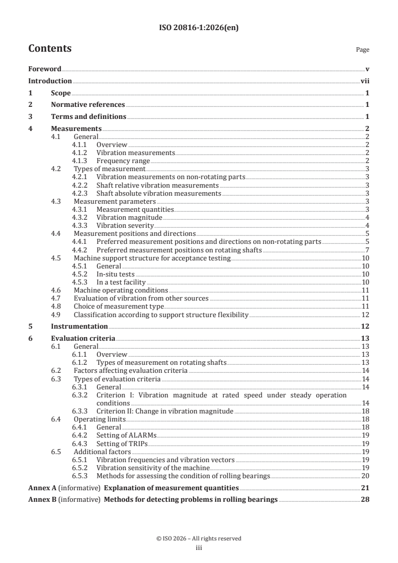
Contents Page
Foreword .v
Introduction .vii
1 Scope . 1
2 Normative references . 1
3 Terms and definitions . 1
4 Measurements . 2
4.1 General .2
4.1.1 Overview .2
4.1.2 Vibration measurements . .2
4.1.3 Frequency range .2
4.2 Types of measurement.3
4.2.1 Vibration measurements on non-rotating parts .3
4.2.2 Shaft relative vibration measurements .3
4.2.3 Shaft absolute vibration measurements .3
4.3 Measurement parameters .3
4.3.1 Measurement quantities . . .3
4.3.2 Vibration magnitude .4
4.3.3 Vibration severity .4
4.4 Measurement positions and directions .5
4.4.1 Preferred measurement positions and directions on non-rotating parts .5
4.4.2 Preferred measurement positions on rotating shafts .7
4.5 Machine support structure for acceptance testing .10
4.5.1 General .10
4.5.2 In-situ tests .10
4.5.3 In a test facility .10
4.6 Machine operating conditions .11
4.7 Evaluation of vibration from other sources .11
4.8 Choice of measurement type .11
4.9 Classification according to support structure flexibility . 12
5 Instrumentation .12
6 Evaluation criteria .13
6.1 General . 13
6.1.1 Overview . 13
6.1.2 Types of measurement on rotating shafts . 13
6.2 Factors affecting evaluation criteria .14
6.3 Types of evaluation criteria .14
6.3.1 General .14
6.3.2 Criterion I: Vibration magnitude at rated speed under steady operation
conditions .14
6.3.3 Criterion II: Change in vibration magnitude .18
6.4 Operating limits .18
6.4.1 General .18
6.4.2 Setting of ALARMs .19
6.4.3 Setting of TRIPs .19
6.5 Additional factors .19
6.5.1 Vibration frequencies and vibration vectors .19
6.5.2 Vibration sensitivity of the machine.19
6.5.3 Methods for assessing the condition of rolling bearings . 20
Annex A (informative) Explanation of measurement quantities .21
Annex B (informative) Methods for detecting problems in rolling bearings .28
iii
Annex C (informative) Guidelines for setting zone boundaries for vibration measured on non-
rotating parts .30
Annex D (informative) Vector analysis of change in vibration .32
Annex E (informative) Methodology for selecting vibration measurements appropriate to the
machine .34
Bibliography .40
iv
Foreword
ISO (the International Organization for Standardization) is a worldwide federation of national standards
bodies (ISO member bodies). The work of preparing International Standards is normally carried out through
ISO technical committees. Each member body interested in a subject for which a technical committee
has been established has the right to be represented on that committee. International organizations,
governmental and non-governmental, in liaison with ISO, also take part in the work. ISO collaborates closely
with the International Electrotechnical Commission (IEC) on all matters of electrotechnical standardization.
The procedures used to develop this document and those intended for its further maintenance are described
in the ISO/IEC Directives, Part 1. In particular the different approval criteria needed for the different types
of ISO documents should be noted. This document was drafted in accordance with the editorial rules of the
ISO/IEC Directives, Part 2 (see www.iso.org/directives).
Attention is drawn to the possibility that some of the elements of this document may be the subject of patent
rights. ISO shall not be held responsible for identifying any or all such patent rights. Details of any patent
rights identified during the development of the document will be in the Introduction and/or on the ISO list of
patent declarations received (see www.iso.org/patents).
Any trade name used in this document is information given for the convenience of users and does not
constitute an endorsement.
For an explanation on the meaning of ISO specific terms and expressions related to conformity assessment,
as well as information about ISO's adherence to the World Trade Organization (WTO) principles in the
Technical Barriers to Trade (TBT) see the following URL: www.iso.org/iso/foreword.html.
This document was prepared by Technical Committee ISO/TC 108, Mechanical vibration, shock and condition
monitoring, Subcommittee SC 2, Measurement and evaluation of mechanical vibration and shock as applied to
machines, vehicles and structures.
This second edition of ISO 20816-1 cancels and replaces the first edition (ISO 20816-1:2016), which has been
technically revised.
The main changes are as follows:
— Introduction was shortened;
— wording in Clause 1 was aligned with ISO directives;
— references in Clause 2 were updated;
— terms in Clause 3 were added and definitions in 4.3.1 removed;
— Figure 5 and Figure 6 were updated;
— 4.8 and 4.9 were added with content from ISO/TR 19201;
— content of B.4 was deleted and merged with B.5;
— Figure C.1 was added;
— C.2 was removed;
— Annex E was added with content from ISO/TR 19201;
— wording in the document was aligned with ISO 20816-3;
— Bibliography was updated;
— document editorially revised;
A list of all parts in the ISO 10816 series and the ISO 20816 series can be found on the ISO website.
v
Any feedback or questions on this document should be directed to the user’s national standards body. A
complete listing of these bodies can be found at www.iso.org/members.html.
vi
Introduction
This document establishes general guidelines for the measurement and evaluation of mechanical machine
vibration, as measured on rotating and on non-rotating parts of complete machines (e.g. shafts or bearing
housings).
Recommendations for measurements and evaluation criteria pertaining to specific machine types are
provided in additional parts of the ISO 20816 series as they become available as a replacement of parts of
the ISO 10816 series.
For some machines, measurements made on non-rotating parts are sufficient to adequately characterize
their running conditions with respect to trouble-free operation. There are also machine types (e.g.
steam turbines, gas turbines and turbo compressors) which can have several modes of vibration in their
operating speed range, for which measurements on the structure (e.g. bearing housings) do not always fully
characterize the running condition of the machine, although such measurements are useful. Such machines
generally contain flexible rotor shaft systems and changes in the vibration condition can be detected
more effectively by measurements on the rotating elements. Machines having stiff and/or heavy housings
in comparison to the rotor mass and/or stiffness are typical of those classes of machines for which shaft
vibration measurements are often more appropriate.
Vibration measurements are used for purposes, ranging from routine operational monitoring and acceptance
tests to advanced experimental testing as well as diagnostic and analytical investigations. These various
measurement objectives lead to many differences in the methods of interpretation and evaluation used. To
limit the number of these differences, this document is designed to provide guidelines primarily for use in
operational monitoring and acceptance tests.
Three primary vibration quantities (displacement, velocity and acceleration) are defined and their
advantages and disadvantages are given.
vii
International Standard ISO 20816-1:2026(en)
Mechanical vibration — Measurement and evaluation of
machine vibration —
Part 1:
General guidelines
1 Scope
This document establishes general principles for the measurement and evaluation of vibration using
measurements made on rotating or non-rotating parts of complete machines. It is applicable to vibration
measurements on non-rotating parts and to both absolute and relative radial shaft vibration with regard
to the monitoring of radial clearances, but does not apply to axial shaft vibration, unless otherwise stated.
The evaluation criteria, which are presented in terms of both vibration magnitude and change in vibration,
relate to both operational monitoring and acceptance tests. They have been provided primarily with regard
to securing reliable, safe, long-term operation of the machine while minimizing any adverse effects on
associated equipment. This document also gives guidance on setting operating limits.
NOTE 1 The evaluation criteria for different machine types are included in other parts of the ISO 10816 series and
the ISO 20816 series.
NOTE 2 The term “shaft vibration” is used throughout the ISO 10816 series and the ISO 20816 series because, in
most cases, vibration measurements are made on machine shafts. However, the ISO 10816 series and the ISO 20816
series are also applicable to measurements made on other rotating elements of the machine if such elements are found
or known to be more suitable, provided that the guidelines set in this document are met.
The evaluation criteria are only applicable to the vibration produced by the machine itself and not the
vibration transmitted to it from outside.
This document does not apply to torsional vibration.
NOTE 3 For information regarding the evaluation of torsional vibration, see e.g. ISO 3046-5, ISO 22266-1 or
VDI 2039.
2 Normative references
The following documents are referred to in the text in such a way that some or all of their content constitutes
requirements of this document. For dated references, only the edition cited applies. For undated references,
the latest edition of the referenced document (including any amendments) applies.
ISO 2041, Mechanical vibration, shock and condition monitoring — Vocabulary
ISO 2954, Mechanical vibration of rotating and reciprocating machinery — Requirements for instruments for
measuring vibration severity
ISO 5348, Mechanical vibration and shock — Mechanical mounting of accelerometers
ISO 10817-1, Rotating shaft vibration measuring systems — Part 1: Relative and absolute sensing of radial
vibration
3 Terms and definitions
For the purposes of this document, the terms and definitions given in ISO 2041 and the following apply.
ISO and IEC maintain terminoly databases for use in standardization at the following addresses:
— IEC Electropedia: available at https:// www .electropedia .org/
— ISO Online browsing platform: available at https:// www .iso .org/ obp
3.1
shaft absolute vibration
absolute shaft vibration
vibration of rotating parts measured with respect to the absolute coordinate
3.2
shaft relative vibration
relative shaft vibration
vibration of rotating parts measured with respect to the transducer support
3.3
pedestal vibration
vibration measured on the pedestal bearing (a non-rotating part)
3.4
seismic vibration
vibration measured on a non- rotating part
3.5
dynamic stiffness of bearing
stiffness of the bearing part including damping and mass effects
3.6
dynamic stiffness of pedestal
stiffness of the bearing support structure including damping and mass effects
3.7
operational monitoring
measurements made during normal operation of a machine
4 Measurements
4.1 General
4.1.1 Overview
Clause 4 describes the measurements, procedures and operating conditions recommended for assessing
machine vibration. The guidelines given enable the evaluation of vibration in accordance with the general
criteria and principles given in Clause 6.
The ISO 10816 series and the ISO 20816 series enable the use of different measurement quantities and
methods provided that they are well-defined and their advantages and disadvantages are set out so that the
interpretation of the measurements is well-understood.
4.1.2 Vibration measurements
It is common practice to measure machine vibration on non-rotating parts or to measure shaft relative
vibration, or both. The measurement type to be used for the protection system is usually based on the
experience of the machine manufacturer.
4.1.3 Frequency range
Vibration measurement shall be broad-band such that the frequency spectrum of the machine is adequately
covered.
The frequency range depends on the machine type being considered (e.g. the frequency range necessary to
assess the integrity of rolling bearings should include frequencies higher than those used on machines with
fluid-film bearings).
For guidelines for instrumentation frequency ranges for specific machine classes see appropriate parts of
the ISO 10816 series and the ISO 20816 series.
NOTE 1 In the past, broad-band measurements in the range from 10 Hz to 1 000 Hz were the intended metric for
full-load acceptance tests. This does not always meet the requirements of a condition monitoring scheme and can be
modified for the purposes of vibration monitoring and diagnostics.
NOTE 2 For vibration condition monitoring and diagnostics of machines see ISO 13373 series.
For certain machine types (e.g. gearboxes and rolling bearings) it can be appropriate to use a different
frequency range for acceptance testing.
4.2 Types of measurement
4.2.1 Vibration measurements on non-rotating parts
Vibration measurements on non-rotating parts are usually taken using a sensor which measures the absolute
velocity or acceleration of the structural parts on which it is mounted (e.g. the bearing housing).
4.2.2 Shaft relative vibration measurements
Shaft relative vibration measurements are usually taken using a non-contacting probe which senses the
displacement between the shaft and the structural part on which it is mounted (e.g. the bearing housing).
NOTE Displacement probes (e.g. non-contacting eddy current sensors) measure the displacement of the rotor or
shaft. The AC portion of the signal is directly proportional to the shaft relative vibration.
4.2.3 Shaft absolute vibration measurements
Shaft absolute vibration measurements are taken using either
a) a shaft-riding probe on which a vibration sensor is mounted so that it measures shaft absolute vibration
directly, or
b) a non-contacting displacement probe which measures shaft relative vibration in combination with a
seismic vibration sensor which measures the housing vibration. Both transducers shall be mounted
close together such that they undergo the same vibration in the direction of measurement. Their
conditioned outputs are summed to provide a measurement of the shaft absolute vibration. To avoid
incorrect results, the same time reference shall be used for the outputs from both the seismic and non-
contacting displacement probes (i.e. synchronous sampling). If this cannot be achieved, the magnitude
of the resulting error shall be assessed.
4.3 Measurement parameters
4.3.1 Measurement quantities
For the purposes of this document, these measurement quantities can be used:
a) displacement measured in µm;
b) velocity measured in mm/s;
c) acceleration measured in m/s .
The use, application and limitations of these quantities are discussed in Clause 6.
There is no simple relationship between broad-band acceleration, velocity and displacement; nor is there
between peak (0–p), peak-to-peak (p–p), root-mean-square (r.m.s.) and average magnitudes of vibration.
The reasons for this are briefly discussed in A.1, which also defines some precise relationships between the
quantities when the harmonic content of the vibration waveform is known.
To avoid confusion and to enable correct interpretation, the measurement quantity and its unit shall
be clearly identified (e.g. peak-to-peak displacement in µm, r.m.s. velocity in mm/s or peak-to-peak shaft
absolute displacement in µm).
NOTE Vibration is a vector quantity and therefore, when comparing two different vibration measurements, it can
be necessary to consider the phase angle between them (see Annex D).
The preferred measurement quantity for the measurement of vibration of non-rotating parts is r.m.s.
velocity while the preferred measurement quantity for the measurement of shaft vibration is peak-to-peak
displacement.
It shall be clearly indicated in measurements taken whether shaft displacement magnitudes are relative or
absolute.
Relative and absolute displacements are further defined by several different displacement quantities, each
of which is in widespread use. These include:
maximum shaft displacement in the plane of measurement, measured from its time integrated
s
max
mean position, see Formula (A.12);
peak-to-peak shaf t displacement in the direction of measurement def ined as
s
(p–p)
s = max {s , s }; and
(p–p) A,(p–p) B,(p–p)
s maximum shaft peak-to-peak displacement in the plane of measurement.
(p–p),max
Any of these displacement quantities may be used for the measurement of shaft vibration. The relationships
between these quantities are shown in Figure A.3.
4.3.2 Vibration magnitude
The result of measurements made with an instrument which complies with the requirements of Clause 5 is
the vibration magnitude at a specific measurement position and direction.
It is common practice, when evaluating the broad-band vibration of rotating machines, to consider the
r.m.s. magnitude of velocity since it can be related to the vibration energy. However, other quantities (e.g.
displacement or acceleration and peak magnitudes instead of r.m.s. magnitudes) can be preferred. In this
case, alternative evaluation criteria, which are not necessarily simply related to r.m.s. magnitudes, are
required.
For shaft vibration measurement, it is common practice to consider peak-to-peak magnitudes.
4.3.3 Vibration severity
Usually, measurements are made at various measurement positions and in one, two or three measurement
directions, leading to a set of different vibration magnitudes. The maximum broad-band magnitude
measured under the agreed machine support structure and operating conditions is defined as the vibration
severity (see also ISO 2041).
For most machine types, one value of vibration severity characterizes the vibratory state of that machine.
However, for some machines, this approach is inadequate and the vibration severity shall then be assessed
independently for measurement positions at several locations.
4.4 Measurement positions and directions
4.4.1 Preferred measurement positions and directions on non-rotating parts
Measurements on non-rotating parts shall be taken on the bearings, the bearing support structure, the
bearing housing or other structural parts which significantly respond to the dynamic forces transmitted
from the rotating elements at the bearing locations and characterize the overall vibration of the machine.
Typical measurement positions are shown in Figure 1 to Figure 5.
To determine the vibrational severity at each measurement position, it is necessary to take measurements
in three mutually perpendicular directions. The full complement of measurements represented in Figure 1
to Figure 5 is generally only required for acceptance tests.
The requirements for operational monitoring are usually met by performing one or both measurements
in the radial direction (usually taken in the horizontal/transverse and/or vertical directions). These can
be supplemented by a vibration measurement in the axial direction. The severity of an axial measurement
is only evaluated at locations representative of thrust bearings where direct axial dynamic forces are
transmitted.
A single radial vibration sensor may be used on a bearing housing or pedestal in place of the more typical
pair of orthogonal sensors if it is known to provide adequate information about the machine’s vibration
magnitude. The positioning of the sensor shall be such that it provides a reasonable approximation of the
maximum magnitude in that plane.
When a single triaxial accelerometer is used, only those axes which are in line with the measurement
positions defined in this document shall be compared with the guidelines given in other parts of the
ISO 20816 series. In particular, a triaxial measurement taken at the top of the bearing is likely to over-
estimate axial and transverse vibration magnitudes. The magnitudes remain useful for trending purposes
as part of a condition monitoring programme.
When a vibration sensor is attached using a bracket, it shall be confirmed that no resonances of the bracket
are affecting the measurement.
Detailed recommendations for specific machine types are provided in the additional parts of the
ISO 10816 series and the ISO 20816 series.
Figure 1 — Preferred measurement positions and directions for pedestal bearings
Figure 2 — Preferred measurement positions and directions for bearing housings
Figure 3 — Preferred measurement positions and directions for machines
Figure 4 — Preferred measurement positions and directions for reciprocating engines close to the
bearing locations
Figure 5 — Preferred measurement positions and directions for vertical machine sets
4.4.2 Preferred measurement positions on rotating shafts
4.4.2.1 General
For the measurements on rotating shafts, the displacement probes shall be mounted at positions such that
the radial movement of the shaft at positions of importance can be assessed. It is recommended that, for both
relative and absolute measurements, two probes shall be located at, or adjacent to each machine bearing
(see Figure 6). They shall be radially mounted in the same plane perpendicular to the shaft axis or as close
as is practicable, with their axes within ±5° of a radial line. A pair of probes shall be mounted 90° ± 5° apart
from each other on the same bearing half and the positions chosen shall be, if possible, the same at each
bearing (see Figure 7).
A single displacement probe may be used at each measurement plane instead of the more typical pair of
orthogonal probes if that is known to provide adequate information regarding shaft vibration.
The positioning of the probe shall be such that it provides a reasonable approximation of the maximum
magnitude in that plane.
It is recommended that special measurements are made to determine the total non-vibration runout, caused
by shaft surface metallurgical non-homogeneities, local residual magnetism and shaft mechanical runout.
For anisotropic rotors (e.g. two-pole generators) the effect of gravity can cause a false runout signal.
Key
1 signal conditioning units
2 non-contacting displacement probes
3 shaft
4 bearing housings
5 bearings
a
To signal processing.
Figure 6 — Preferred measurement positions on rotating shafts
Key
1 signal conditioning units
2 shaft
3 non-contacting displacement probes
a
To signal processing.
Figure 7 — Preferred measurements positions on rotating shafts
4.4.2.2 Measurement positions for shaft relative vibration
Non-contacting displacement probes used to make shaft relative vibration measurements are usually
mounted in tapped holes in the bearing housing or in rigid brackets adjacent to the bearing housing or
bearing shell. Where the probes are mounted in the bearing, they shall be located so as not to interfere
with the lubrication pressure wedge. However, special arrangements for mounting probes in other axial
measurement positions may be made, but different vibration criteria for assessment shall then be used. For
bracket-mounted probes, the bracket shall not have natural frequencies which adversely affect the capability
of the probe to measure the shaft relative vibration.
The surface of the shaft at the measurement position, considering the total axial float of the shaft under all
thermal conditions, shall be smooth and free from any geometric discontinuities (e.g. keyways, lubrication
passages and threads), metallurgical non-homogeneities and local residual magnetism which can cause false
signals. Under certain circumstances, an electroplated or metallized shaft surface is acceptable, but note
that the calibration can be affected. It is recommended that the total combined electrical and mechanical
runout, as measured by the displacement probe, does not exceed 25 % of the acceptable displacement
specified in 6.3.2.2 or 6 μm, whichever is greater. For measurements made on machines already in service,
where provision was not originally made for shaft vibration measurements, it is sometimes necessary to use
other runout criteria.
4.4.2.3 Measurement positions for shaft absolute vibration using combined vibration sensors and
non-contacting displacement probes
If a combination of vibration sensors and non-contacting displacement probes is used, the shaft absolute
vibration is obtained by
a) integrating the signal from the vibration sensor to convert the acceleration or velocity output to
displacement, and
b) summing the raw time domain displacement outputs from both sensors.
To avoid obtaining incorrect results, the same time reference shall be used for the outputs from both the
seismic and non-contacting displacement probes (i.e. synchronous sampling).
The mounting and other requirements for non-contacting displacement probes are specified in 4.4.2.2. In
addition, the vibration sensor shall be rigidly mounted to the machine structure (e.g. the bearing housing)
close to the non-contacting displacement probe so that both transducers undergo the same vibration of the
support structure in the direction of measurement. The sensitive axes of the probe and vibration sensor shall
be parallel, so that their summed, conditioned signals result in an accurate measure of the shaft absolute
vibration (see Figure 8).
Accelerometers for vibration measurements on non-rotating parts shall be mounted in accordance with
ISO 5348.
NOTE In the past, shaft absolute vibration measurements have also been performed using a shaft-riding
mechanism with a vibration sensor.
Key
1 signal conditioning units
2 shaft
3 non-contacting displacement probes
4 vibration sensors
a
To signal processing.
Figure 8 — Mounting of non-contacting displacement probes and seismic probes for the
measurement of shaft absolute vibration
4.5 Machine support structure for acceptance testing
4.5.1 General
The acceptance criteria shall be agreed between the customer and the machine manufacturer.
4.5.2 In-situ tests
When acceptance testing is carried out in-situ, the support structure supplied for the machine shall be used.
In this case, the test shall be carried out when all the major components of the machine and structure have
been installed.
Comparisons of vibration for machines of the same type but installed on different foundations or sub-
foundations may only be made if the foundations concerned have similar dynamic characteristics.
4.5.3 In a test facility
There are machines for which, because of economic or other reasons, acceptance testing is carried out
on a test bed which can have different support structure characteristics from those on site. The support
structure can significantly affect the measured vibration and every effort shall be made to confirm that the
natural frequencies of the complete test arrangement do not coincide with the rotational frequencies of the
machine or with any of its significant harmonics.
The test arrangement usually meets these requirements if the vibration magnitude measured in the
horizontal and vertical directions at the machine feet, or at the base frame near the bearing support
structure or stator feet, does not exceed 50 % of the vibration magnitude measured in the same measurement
direction at that bearing. Additionally, the test arrangement shall not cause a substantial change in any of
the natural frequencies.
If a significant support structural resonance is present during acceptance testing and it cannot be eliminated,
the vibration acceptance test shall be carried out on the fully installed machine in-situ.
For some classes of machine (e.g. small electrical machines), acceptance tests can be carried out when they
are supported by a resilient system (see e.g. IEC 60034-14). In this case, all the rigid-body mode frequencies
of the machine on its support structure shall be <50 % of the lowest significant excitation frequency of the
machine. Appropriate support conditions can be achieved by mounting the machine on a resilient support
baseplate or by free suspension on a soft spring.
4.6 Machine operating conditions
Vibration measurements shall be made after achieving the agreed normal operating conditions (e.g. rated
speed, load, temperature pressure, etc.). Vibration measurements that are taken under other machine
operating conditions are not applicable for evaluation in accordance with Clause 6.
4.7 Evaluation of vibration from other sources
If the measured vibration magnitude exceeds the recommended Zone B/C boundary, it can be necessary
to take measurements of environmental vibration with the machine shut down to confirm that this is not
contributing significantly to the measured vibration magnitude. Where possible, steps shall be taken to
reduce the magnitude of environmental vibration if it is >1/3 of the Zone B/C boundary.
4.8 Choice of measurement type
In this document, guidelines are provided for measurement on both rotating and non-rotating parts. The
choice of which measurement type to use depends upon the characteristics of the machine and the faults
which need to be detected.
The advantages or disadvantages of vibration measurements on rotating or non-rotating parts shall be
considered based upon:
a) Machine speed and highest frequency of interest:
Measurements taken on non-rotating parts are more sensitive to higher frequencies than measurements
taken on rotating parts;
b) Bearing type:
Rolling bearings have very small clearances and transmit shaft vibration effectively into their housings.
Therefore, measurements taken on non-rotating parts are usually sufficient to enable effective vibration
monitoring and machine assessment. Journal bearings provide high damping and larger clearances so
shaft vibration is often a useful additional parameter to measure;
c) Machine type:
Machines with internal clearances comparable to the vibration magnitude can require the measurement
of shaft relative vibration for protection purposes (see Annex C). Monitoring of components that
generate multiples of rotational speed (e.g. vanes, gear teeth [including gear pumps], blades, rotor bars)
benefit from the higher frequency range available with measurements taken on non-rotating parts;
d) Ratio of shaft mass to pedestal mass:
Light shafts in heavy pedestals transmit little vibration into the bearing housing, so shaft relative
vibration measurements provide a better indication of machine behaviour;
e) Shaft flexibility:
Shaft relative vibration measurements provide a more sensitive indication of vibration severity in
machines with flexible shafts;
f) Support structure flexibility:
Flexible support structures lead to a higher vibration response of non-rotating parts;
g) Experience:
Where a large body of experience exists relating to one particular measurement type, it is useful to
continue to use it in similar situations.
For more detailed information on the choice of the appropriate measurement method see Annex E and
ISO 13373-1. Considerations relating to ease of access, longevity of sensors and cost of installation are also
relevant to the final decision (see ISO 17359).
4.9 Classification according to support structure flexibility
Two classes are used to denote the support structure flexibility in specified directions:
a) rigid;
b) flexible.
These support structure conditions are determined by the relationship between the machine and foundation
flexibilities. If the lowest natural frequency of the system exceeds the excitation frequency by >25 % then
the machine may be considered rigid.
The excitation frequency is usually related to rotational speed, but significant other excitations (e.g. vane
passing or gear mesh) can be important. Machines on anti-vibration mounts shall be classified as flexible.
It is possible for machines to be rigid in one direction and flexible in another (e.g. pedestal bearings tend to
vibrate much more in the transverse direction than in the vertical direction).
If the class of the machine support structure cannot be readily determined from drawings and calculation, it
can be determined by testing, see also Annex E.
5 Instrumentation
The instrumentation used shall be designed to operate satisfactorily in the environment for which it is
to be used (e.g. with respect to temperature and humidity). Specifications for instruments for measuring
vibration on non-rotating parts shall be in accordance with the requirements of ISO 2954. Instruments for
measuring vibration on rotating parts shall be in accordance with the requirements of ISO 10817-1.
For measurement on non-rotating parts, the vibration sensor shall be correctly mounted. It may not, as far
as reasonably practicable, affect the vibration response characteristics of the machine. The requirements for
mounting accelerometers on the machine described in ISO 5348 shall be followed. These are also applicable,
in principle, to the mounting of velocity transducers.
Instrumentation can provide multiple methods to deliver a measurement value. The acceptance criteria
in this document are based on r.m.s. velocity in mm/s for measurements on non-rotating parts and peak-
to-peak displacement in µm for measurements on rotating parts. The acceptance criteria shall be scaled
suitably to match the units in common use at the site, using the same assumptions as programmed into the
distributed control systems. The assumptions are based on the
...