


IEC 60623:2026
(Main)Secondary cells and batteries containing alkaline or other non-acid electrolytes - Vented nickel-cadmium prismatic rechargeable cells and batteries for use in industrial applications
General Information
- Abstract
IEC 60623:2026 specifies marking, designation, dimensions, tests and requirements for vented nickel-cadmium prismatic secondary single cells and battery systems made of them for use in industrial applications.
This sixth edition cancels and replaces the fifth edition published in 2017. This edition constitutes a technical revision.
This edition includes the following significant technical changes with respect to the previous edition:
a) added a test for internal DC resistance;
b) added a subclause for pulse power calculation;
c) added a test for constant power measurement;
d) added a subclause on the determination of durability parameters.
- Status
- Published
- Publication Date
- 23-Aug-2026
- Technical Committee
- SC 21A - Secondary cells and batteries containing alkaline or other non-acid electrolytes
- Drafting Committee
- WG 1 - TC 21/SC 21A/WG 1
- Current Stage
- PPUB - Publication issued
- Start Date
- 24-Aug-2026
- Completion Date
- 26-Jun-2026
Buy Documents
REDLINE IEC 60623:2026 CMV - Secondary cells and batteries containing alkaline or other non-acid electrolytes - Vented nickel-cadmium prismatic rechargeable cells and batteries for use in industrial applications
iec60623{ed6.0}en - Secondary cells and batteries containing alkaline or other non-acid electrolytes - Vented nickel-cadmium prismatic rechargeable cells and batteries for use in industrial applications
iec60623{ed6.0}fr - Accumulateurs alcalins et autres accumulateurs a électrolyte non acide - Accumulateurs parallélépipédiques rechargeables ouverts au nickel-cadmium pour utilisation dans des applications industrielles
Overview
IEC 60623:2026 is an international standard developed by the International Electrotechnical Commission (IEC) that specifies requirements for secondary cells and batteries containing alkaline or other non-acid electrolytes. Specifically, this standard applies to vented nickel-cadmium (NiCd) prismatic rechargeable single cells and battery systems designed for industrial applications. The sixth edition of IEC 60623 reflects a comprehensive technical revision, including several key updates to ensure alignment with current industrial needs and technological advances.
This document covers essential criteria such as marking, designation, cell and battery dimensions, testing procedures, and performance requirements. It aims to deliver harmonized quality and safety benchmarks for manufacturers, integrators, and end-users employing NiCd batteries in a wide spectrum of demanding industrial environments.
Key Topics
- Scope and Definitions: Covers prismatic NiCd rechargeable cells and battery systems, providing terminology and symbols relevant to battery manufacturers and industrial users.
- Designation and Marking: Details requirements for cell and battery identification, including mandatory and optional markings indicating discharge rates, materials, tested temperatures, and special test conditions.
- Dimensions: Specifies dimensional requirements for various prismatic cell and battery constructions, supporting standardization and interchangeability.
- Testing Requirements: Sets forth test methodologies and acceptance criteria for electrical performance-including charge, discharge, endurance, internal resistance, and environmental robustness.
- Performance Requirements: Outlines requirements for rated capacity, nominal voltage, charge retention, operational lifespan, and deep discharge endurance.
- Safety Recommendations: Provides guidelines for safe operation, marking, and handling of prismatic NiCd cells in industrial applications.
- Technical Updates: The 2026 edition introduces:
- A test for internal DC resistance
- A subclause for pulse power calculation
- A test for constant power measurement
- A new subclause for determination of durability parameters
Applications
IEC 60623:2026 is highly relevant for a range of industrial battery applications, ensuring correct battery system configuration, predictable performance, and safety. Typical use cases include:
- Stationary Power Backup: Utilized in telecommunications, power plants, and critical infrastructure for uninterruptible power supply (UPS) systems.
- Railway and Mass Transit: Supports essential onboard and signaling systems that demand robust and reliable energy storage.
- Renewable Energy Integration: Used in energy storage solutions for solar and wind installations requiring consistent charge/discharge cycles.
- Industrial Equipment: Powers mobile and stationary equipment where reliability, durability, and performance under variable temperature and cycling conditions are critical.
- Emergency Systems: Provides backup for alarm systems, emergency lighting, and safety-critical operations.
Industrial end users, battery system integrators, and manufacturers benefit from the clear guidelines on marking, performance testing, and product qualification, promoting consistent product quality and operational reliability.
Related Standards
To support proper application and conformity assessment, IEC 60623:2026 references and aligns with several related standards, including:
- IEC 60050-482: International Electrotechnical Vocabulary - Part 482: Primary and secondary cells and batteries (for terminology and definitions).
- IEC 61434: Guide to designation of current in alkaline secondary cell and battery standards.
- IEC 60417: Graphical symbols for use on equipment, ensuring proper battery labeling and instructions.
- Other relevant IEC standards for battery management systems and safety compliance.
Compliance with IEC 60623:2026 ensures manufacturers and users meet global requirements for industrial rechargeable NiCd batteries, facilitating international trade, system integration, and safety assurance.
By adhering to IEC 60623:2026, organizations can enhance the reliability, safety, and interoperability of industrial battery systems, supporting a broad range of essential applications across multiple sectors.
Relations
- Effective Date
- 28-Jun-2024
Buy Documents
REDLINE IEC 60623:2026 CMV - Secondary cells and batteries containing alkaline or other non-acid electrolytes - Vented nickel-cadmium prismatic rechargeable cells and batteries for use in industrial applications
iec60623{ed6.0}en - Secondary cells and batteries containing alkaline or other non-acid electrolytes - Vented nickel-cadmium prismatic rechargeable cells and batteries for use in industrial applications
iec60623{ed6.0}fr - Accumulateurs alcalins et autres accumulateurs a électrolyte non acide - Accumulateurs parallélépipédiques rechargeables ouverts au nickel-cadmium pour utilisation dans des applications industrielles
Get Certified
Connect with accredited certification bodies for this standard

IMQ S.p.A. (Certification)
Italian electrical product certification.

SLG Prüf- und Zertifizierungs GmbH
German testing and certification body.

UL Solutions
Global safety science company with testing, inspection and certification.
Sponsored listings
Frequently Asked Questions
IEC 60623:2026 is a standard published by the International Electrotechnical Commission (IEC). Its full title is "Secondary cells and batteries containing alkaline or other non-acid electrolytes - Vented nickel-cadmium prismatic rechargeable cells and batteries for use in industrial applications". This standard covers: IEC 60623:2026 specifies marking, designation, dimensions, tests and requirements for vented nickel-cadmium prismatic secondary single cells and battery systems made of them for use in industrial applications. This sixth edition cancels and replaces the fifth edition published in 2017. This edition constitutes a technical revision. This edition includes the following significant technical changes with respect to the previous edition: a) added a test for internal DC resistance; b) added a subclause for pulse power calculation; c) added a test for constant power measurement; d) added a subclause on the determination of durability parameters.
IEC 60623:2026 specifies marking, designation, dimensions, tests and requirements for vented nickel-cadmium prismatic secondary single cells and battery systems made of them for use in industrial applications. This sixth edition cancels and replaces the fifth edition published in 2017. This edition constitutes a technical revision. This edition includes the following significant technical changes with respect to the previous edition: a) added a test for internal DC resistance; b) added a subclause for pulse power calculation; c) added a test for constant power measurement; d) added a subclause on the determination of durability parameters.
IEC 60623:2026 is classified under the following ICS (International Classification for Standards) categories: 29.220.99 - Other cells and batteries. The ICS classification helps identify the subject area and facilitates finding related standards.
IEC 60623:2026 has the following relationships with other standards: It is inter standard links to IEC 60623:2017. Understanding these relationships helps ensure you are using the most current and applicable version of the standard.
IEC 60623:2026 is available in PDF format for immediate download after purchase. The document can be added to your cart and obtained through the secure checkout process. Digital delivery ensures instant access to the complete standard document.
Standards Content (Sample)
IEC 60623 ®
Edition 6.0 2026-08
INTERNATIONAL
STANDARD
COMMENTED VERSION
Secondary cells and batteries containing alkaline or other non-acid electrolytes -
Vented nickel-cadmium prismatic rechargeable single cells and batteries for use
in industrial applications
ICS 29.220.99 ISBN 978-2-8327-1471-3
All rights reserved. Unless otherwise specified, no part of this publication may be reproduced or utilized in any form or
by any means, electronic or mechanical, including photocopying and microfilm, without permission in writing from either
IEC or IEC's member National Committee in the country of the requester. If you have any questions about IEC copyright
or have an enquiry about obtaining additional rights to this publication, please contact the address below or your local
IEC member National Committee for further information.
IEC Secretariat Tel.: +41 22 919 02 11
3, rue de Varembé info@iec.ch
CH-1211 Geneva 20 www.iec.ch
Switzerland
About the IEC
The International Electrotechnical Commission (IEC) is the leading global organization that prepares and publishes
International Standards for all electrical, electronic and related technologies.
About IEC publications
The technical content of IEC publications is kept under constant review by the IEC. Please make sure that you have the
latest edition, a corrigendum or an amendment might have been published.
IEC publications search - IEC Products & Services Portal - products.iec.ch
webstore.iec.ch/advsearchform Discover our powerful search engine and read freely all the
The advanced search enables to find IEC publications by a publications previews, graphical symbols and the glossary.
variety of criteria (reference number, text, technical With a subscription you will always have access to up to date
committee, …). It also gives information on projects, content tailored to your needs.
replaced and withdrawn publications.
Electropedia - www.electropedia.org
IEC Just Published - webstore.iec.ch/justpublished The world's leading online dictionary on electrotechnology,
Stay up to date on all new IEC publications. Just Published containing more than 22 500 terminological entries in English
details all new publications released. Available online and and French, with equivalent terms in 25 additional languages.
once a month by email. Also known as the International Electrotechnical Vocabulary
(IEV) online.
IEC Customer Service Centre - webstore.iec.ch/csc
If you wish to give us your feedback on this publication or
need further assistance, please contact the Customer
Service Centre: sales@iec.ch.
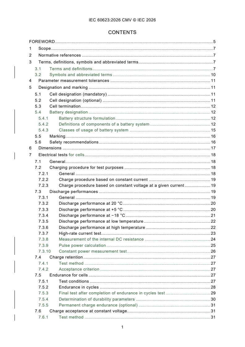
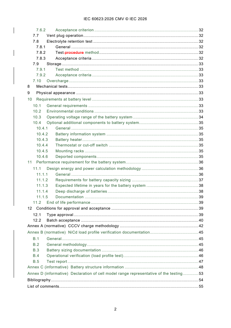
CONTENTS
FOREWORD . 5
1 Scope . 7
2 Normative references . 7
3 Terms, definitions, symbols and abbreviated terms . 7
3.1 Terms and definitions. 7
3.2 Symbols and abbreviated terms . 10
4 Parameter measurement tolerances . 11
5 Designation and marking . 11
5.1 Cell designation (mandatory) . 11
5.2 Cell designation (optional) . 11
5.3 Cell termination . 12
5.4 Battery designation . 12
5.4.1 Battery structure formulation . 12
5.4.2 Definitions of components of a battery system . 12
5.4.3 Classes of usage of battery system . 15
5.5 Marking . 16
5.6 Safety recommendations . 16
6 Dimensions . 17
7 Electrical tests for cells . 18
7.1 General . 18
7.2 Charging procedure for test purposes . 18
7.2.1 General . 18
7.2.2 Charge procedure based on constant current . 19
7.2.3 Charge procedure based on constant voltage at a given current . 19
7.3 Discharge performances . 19
7.3.1 General . 19
7.3.2 Discharge performance at 20 °C . 20
7.3.3 Discharge performance at +5 °C . 20
7.3.4 Discharge performance at −18 °C . 21
7.3.5 Discharge performance at low temperature . 22
7.3.6 Discharge performance at high temperature . 22
7.3.7 High-rate current test . 23
7.3.8 Measurement of the internal DC resistance . 24
7.3.9 Pulse power calculation . 25
7.3.10 Constant power measurement test . 26
7.4 Charge retention . 27
7.4.1 Test method . 27
7.4.2 Acceptance criterion . 27
7.5 Endurance for cells . 27
7.5.1 Test conditions . 27
7.5.2 Endurance in cycles . 28
7.5.3 Final test after completion of endurance in cycles test . 29
7.5.4 Determination of durability parameters . 30
7.5.5 Permanent charge endurance (optional) . 31
7.6 Charge acceptance at constant voltage. 31
7.6.1 Test method . 31
7.6.2 Acceptance criterion . 32
7.7 Vent plug operation . 32
7.8 Electrolyte retention test . 32
7.8.1 General . 32
7.8.2 Test procedure method . 32
7.8.3 Acceptance criteria . 32
7.9 Storage . 33
7.9.1 Test method . 33
7.9.2 Acceptance criteria . 33
7.10 Overcharge . 33
8 Mechanical tests . 33
9 Physical appearance . 33
10 Requirements at battery level . 33
10.1 General requirements . 33
10.2 Environmental conditions . 33
10.3 Operating voltage range of the battery system . 34
10.4 Optional additional components to battery system. 35
10.4.1 General . 35
10.4.2 Battery information system . 35
10.4.3 Battery heater . 35
10.4.4 Thermostat or cut-off switch . 35
10.4.5 Mounting racks . 35
10.4.6 Deported components . 35
11 Performance requirement for the battery system . 36
11.1 Design energy and power calculation methodology . 36
11.1.1 General . 36
11.1.2 Requirements for battery capacity sizing . 37
11.1.3 Expected lifetime in years for the battery system . 38
11.1.4 Deep discharge of batteries . 38
11.1.5 Documentation . 39
11.2 End of life performance . 39
12 Conditions for approval and acceptance . 39
12.1 Type approval . 39
12.2 Batch acceptance . 40
Annex A (normative) CCCV charge methodology . 42
Annex B (normative) NiCd load profile verification documentation . 45
B.1 General . 45
B.2 General methodology . 45
B.3 Battery sizing documentation . 46
B.4 Operational verification (load profile test) . 46
B.5 Test report . 47
Annex C (informative) Battery structure information . 48
Annex D (informative) Declaration of cell model range representative of the testing . 53
Bibliography . 54
List of comments. 55
Figure 1 – Definition of cell(s), monobloc battery, crate, tray, and box - Example of
mobile application . 13
Figure 2 – Definition of cell(s), crate/block/module, battery, cabinet - Example of
stationary application for telecom . 14
Figure 3 – Definition of cell(s), crate/block/module, battery, rack - Example of
stationary application . 15
Figure 4 – Example of a vented prismatic cell in steel container with two terminals and
four lugs . 17
Figure 5 – Pulse discharge graph: voltage behaviour under a current pulse . 26
Figure 6 – Example of a NiCd cell discharge curve at various constant discharge
currents based on percentage of capacity . 34
Figure A.1 – Overview of charging characteristic of NiCd . 44
Figure C.1 – Cells connected in series . 49
Figure C.2 – Two cells connected in parallel . 49
Figure C.3 – Three cells connected in series, with two series strings connected in
parallel . 49
Figure C.4 – Two cells connected in parallel, with four parallel strings connected in
series . 50
Figure C.5 – Two cells connected in parallel, with four parallel strings connected in
series, and with three parallel and series connected strings connected in parallel . 50
Figure C.6 – Two cells connected in parallel, with four parallel strings connected in
series, and with three parallel and series connected strings connected in parallel . 51
Figure C.7 – Three cells connected in series, with two series strings connected in
parallel, and with three series and parallel connected strings connected in parallel . 51
Figure C.8 – Four monoblocs connected in series, with each monobloc comprising
five cells . 51
Figure C.9 – Three cells connected in series, with two series strings connected in
parallel, and with three series and parallel connected strings connected in parallel . 52
Table 1 – Example of dimensions for vented nickel-cadmium prismatic cells in steel
containers . 17
Table 2 – Example of dimensions for vented nickel-cadmium prismatic cells in plastic
containers . 18
Table 3 – Measurement tolerances in millimetres (valid for widths and lengths) . 18
Table 4 – Maximum Preferred values for rapid charge current R . 19
Table 5 – Discharge performance at 20 °C . 20
Table 6 – Discharge performance at +5 °C . 21
Table 7 – Discharge performance at −18 °C . 21
Table 8 – Discharge performance at low temperature . 22
Table 9 – Discharge performance at high temperature . 23
Table 10 – High currents values . 24
Table 11 – Discharge current and pulse current applied during the measurement of the
internal DC resistance . 25
Table 12 – Endurance in cycles . 28
Table 13 – Constant voltage charging conditions . 31
Table 14 – Charge time . 32
Table 15 – Parameters and responsibility for battery capacity sizing . 38
Table 16 – Sequence of tests for type approval . 40
Table 17 – Recommended test sequence for batch acceptance . 41
Table A.1 – Ni-Cd batteries charging characteristics . 43
Table C.1 – Battery structure information - Examples . 48
INTERNATIONAL ELECTROTECHNICAL COMMISSION
____________
Secondary cells and batteries containing alkaline or other non-acid
electrolytes - Vented nickel-cadmium prismatic rechargeable single cells
and batteries 1 for use in industrial applications
FOREWORD
1) The International Electrotechnical Commission (IEC) is a worldwide organization for standardization comprising
all national electrotechnical committees (IEC National Committees). The object of IEC is to promote international
co-operation on all questions concerning standardization in the electrical and electronic fields. To this end and
in addition to other activities, IEC publishes International Standards, Technical Specifications, Technical Reports,
Publicly Available Specifications (PAS) and Guides (hereafter referred to as "IEC Publication(s)"). Their
preparation is entrusted to technical committees; any IEC National Committee interested in the subject dealt with
may participate in this preparatory work. International, governmental and non-governmental organizations liaising
with the IEC also participate in this preparation. IEC collaborates closely with the International Organization for
Standardization (ISO) in accordance with conditions determined by agreement between the two organizations.
2) The formal decisions or agreements of IEC on technical matters express, as nearly as possible, an international
consensus of opinion on the relevant subjects since each technical committee has representation from all
interested IEC National Committees.
3) IEC Publications have the form of recommendations for international use and are accepted by IEC National
Committees in that sense. While all reasonable efforts are made to ensure that the technical content of IEC
Publications is accurate, IEC cannot be held responsible for the way in which they are used or for any
misinterpretation by any end user.
4) In order to promote international uniformity, IEC National Committees undertake to apply IEC Publications
transparently to the maximum extent possible in their national and regional publications. Any divergence between
any IEC Publication and the corresponding national or regional publication shall be clearly indicated in the latter.
5) IEC itself does not provide any attestation of conformity. Independent certification bodies provide conformity
assessment services and, in some areas, access to IEC marks of conformity. IEC is not responsible for any
services carried out by independent certification bodies.
6) All users should ensure that they have the latest edition of this publication.
7) No liability shall attach to IEC or its directors, employees, servants or agents including individual experts and
members of its technical committees and IEC National Committees for any personal injury, property damage or
other damage of any nature whatsoever, whether direct or indirect, or for costs (including legal fees) and
expenses arising out of the publication, use of, or reliance upon, this IEC Publication or any other IEC
Publications.
8) Attention is drawn to the Normative references cited in this publication. Use of the referenced publications is
indispensable for the correct application of this publication.
9) IEC draws attention to the possibility that the implementation of this document may involve the use of (a)
patent(s). IEC takes no position concerning the evidence, validity or applicability of any claimed patent rights in
respect thereof. As of the date of publication of this document, IEC had not received notice of (a) patent(s), which
may be required to implement this document. However, implementers are cautioned that this may not represent
the latest information, which may be obtained from the patent database available at https://patents.iec.ch. IEC
shall not be held responsible for identifying any or all such patent rights.
This commented version (CMV) of the official standard IEC 60623:2026 edition 6.0 allows the
user to identify the changes made to the previous IEC 60623:2017 edition 5.0. Furthermore,
comments from IEC subcommittee 21A experts are provided to explain the reasons of the most
relevant changes, or to clarify any part of the content.
A vertical bar appears in the margin wherever a change has been made. Additions are in green
text, deletions are in strikethrough red text. Experts' comments are identified by a blue-
background number. Mouse over a number to display a pop-up note with the comment.
This publication contains the CMV and the official standard. The full list of comments is available
at the end of the CMV.
IEC 60623 has been prepared by subcommittee 21A: Secondary cells and batteries containing
alkaline or other non-acid electrolytes, of IEC technical committee 21: Secondary cells and
batteries. It is an International Standard.
This sixth edition cancels and replaces the fifth edition published in 2017. This edition
constitutes a technical revision.
This edition includes the following significant technical changes with respect to the previous
edition:
a) added a test for internal DC resistance;
b) added a subclause for pulse power calculation;
c) added a test for constant power measurement;
d) added a subclause on the determination of durability parameters.
The text of this International Standard is based on the following documents:
Draft Report on voting
21A/935/CDV 21A/959/RVC
Full information on the voting for its approval can be found in the report on voting indicated in
the above table.
The language used for the development of this International Standard is English.
This document was drafted in accordance with ISO/IEC Directives, Part 2, and developed in
accordance with ISO/IEC Directives, Part 1 and ISO/IEC Directives, IEC Supplement, available
at http://www.iec.ch/members_experts/refdocs. The main document types developed by IEC
are described in greater detail at http://www.iec.ch/publications.
The committee has decided that the contents of this document will remain unchanged until the
stability date indicated on the IEC website under http://webstore.iec.ch in the data related to
the specific document. At this date, the document will be
– reconfirmed,
– withdrawn, or
– revised.
1 Scope
This document specifies marking, designation, dimensions, tests and requirements for vented
nickel-cadmium prismatic secondary single cells and battery systems made of them for use in
industrial applications. 1
NOTE In this context, "prismatic" refers to cells having rectangular sides and base.
When there exists an IEC standard specifying test conditions and requirements for cells used
in special applications and which is in conflict with this document, the former takes precedence.
2 Normative references
The following documents are referred to in the text in such a way that some or all of their content
constitutes requirements of this document. For dated references, only the edition cited applies.
For undated references, the latest edition of the referenced document (including any
amendments) applies.
IEC 60050-482:2004, International Electrotechnical Vocabulary (IEV) - Part 482: Primary and
secondary cells and batteries
IEC 60050-482:2004/AMD2:2020, International Electrotechnical Vocabulary (IEV) - Part 482:
Primary and secondary cells and batteries
IEC 61434, Secondary cells and batteries containing alkaline or other non-acid electrolytes -
Guide to designation of current in alkaline secondary cell and battery standards
IEC 60417, Graphical symbols for use on equipment, available at http://www.graphical-
symbols.info/equipment
3 Terms, definitions, symbols and abbreviated terms
3.1 Terms and definitions
For the purposes of this document, the terms and definitions given in IEC 60050-482:2004 and
the following apply.
ISO and IEC maintain terminology databases for use in standardization at the following
addresses:
– IEC Electropedia: available at https://www.electropedia.org/
– ISO Online browsing platform: available at https://www.iso.org/obp
3.1.1
vented cell
secondary cell having a cover provided with an opening through which products of electrolysis
and evaporation are allowed to escape freely from the cell to the atmosphere
Note 1 to entry: The opening may can be fitted with a venting system.
Note 2 to entry: The vented cell is the smallest unit manufactured in series, and the primary vehicle for electrical
characterization.
3.1.2
monobloc battery
battery with multiple separate but electrically connected cell compartments each of which is
designed to house an assembly of electrodes, electrolyte, terminals or interconnections and
possible separators
Note 1 to entry: The cells in a monobloc battery can be connected in series or in parallel.
Note 2 to entry: See 5.4.2.
[SOURCE: IEC 60050-482:2004 [1], 482-02-17, modified – Note 2 to entry has been added.]
3.1.3
crate
container with frame walls for holding several cells or batteries 2
Note 1 to entry: See 5.4.2.
[SOURCE: IEC 60050-482:2004 [1], 482-05-10, modified – The word "battery" has been
removed from the term, and Note 1 to entry has been added.]
3.1.4
tray
container with a base and walls for holding several cells or batteries 3
Note 1 to entry: See 5.4.2.
[SOURCE: IEC 60050-482:2004 [1], 482-02-35, modified – The word "battery" has been
removed from the tterm, and Note 1 to entry has been added.]
3.1.5
ageing factor
quantitative factor expressing the degradation in the ability of the battery, due to usage, to
deliver electrical energy under specified operating conditions such as, but not limited to,
operating ambient temperature, cycling considering depth of discharge (DOD), and
maintenance practices (applied according to manufacturer's instructions)
3.1.6
battery module
module
group of cells connected together either in a series or parallel, or both configuration, without
protective devices
Note 1 to entry: NiCd battery module does not include any hardware (e.g. fuse or electronic board). 4
Note 2 to entry: Protective devices (e.g. temperature sensor) are part of the battery system.
3.1.7
battery system
battery
system that can include battery tray(s), battery crate(s), monobloc(s), battery module(s),
electronic components/equipment and associated electromechanical connections
Note 1 to entry: Any component necessary to obtain the safety and durability of the battery system is included (e.g.
battery thermal management system, BTMS)
Note 2 to entry: See 5.4.2 and 10.1.
Note 3 to entry: The battery system manufacturer can be the end user or the equipment manufacturer, in case they
install for example heating/cooling systems, ventilation common to the global equipment but necessary for the
battery.
Note 4 to entry: The battery system performances are derived from cell electrical characterization.
3.1.8
battery information system
electronic system collecting and analyzing battery data to provide additional information, i.e.
information not necessary for battery operation
Note 1 to entry: Additional information, for example, can be parameters necessary for condition-based maintenance.
3.1.9
end user
organization which operates the battery system
Note 1 to entry: The end user is normally an organization which operates the device equipped with the battery
system, unless the responsibility is delegated to a main contractor or consultant.
3.1.10
system integrator
organization which has the technical responsibility of the complete battery system and charging
system
Note 1 to entry: The system integrator can be the end user or the equipment manufacturer, or none of them.
3.1.11
manufacturer
organization which has the technical responsibility for its scope of supply
Note 1 to entry: The manufacturer can be the equipment manufacturer or the system integrator of a battery system,
a cell manufacturer, etc. If necessary to explicitly distinguish, "equipment manufacturer", "battery system
manufacturer" or "cell manufacturer" is expressed.
3.1.12
cumulated requested service
CRS
total amount of service requested by the buyer or the end user, expressed in duration (months
or years) or delivered energy in kWh, under for example representative ambient and operating
conditions as expressed 5
Note 1 to entry: Refer to Clause 10 and Clause 11.
3.1.13
nominal voltage
suitable approximate value of the voltage used to designate or identify a cell or a battery
Note 1 to entry: The nominal voltage of a vented nickel-cadmium rechargeable single cell is 1,2 V.
Note 2 to entry: The nominal voltage of a battery of n series connected cells is equal to n times the nominal voltage
of a single cell.
[SOURCE: IEC 60050-482:2004 [1], 482-03-31, modified – Replacement of the words "a battery
or an electrochemical system" by "or a battery" and addition of Notes 1 and 2 to entry.]
3.1.14
discharge voltage
closed circuit voltage
DEPRECATED: on load voltage
voltage between the terminals of a cell or battery when being discharged
[SOURCE: IEC 60050-482:2004 [1], 482-03-28, modified – The admitted and deprecated terms
have been removed.]
3.1.15
rated capacity
capacity value of a cell or battery determined under specified conditions and declared by the
manufacturer
Note 1 to entry: The rated capacity is the quantity of electricity C Ah (ampere-hours) declared by the manufacturer
which a single cell can deliver during a 5 h period when charging, storing and discharging under the conditions
specified in 7.3.2.
[SOURCE: IEC 60050-482:2004 [1], 482-03-15, modified – Addition of the words "cell or" in the
definition, and of Note 1 to entry.]
3.1.16
state of charge
SOC
remaining capacity to be discharged, normally expressed as a percentage of the cell rated
capacity according to 7.3.2.2
3.1.17
state of charge at end of life
SOC at end of life
remaining capacity to be discharged at end of life, normally expressed as 70 % of the cell rated
capacity 6 (3 h 30 min discharge with 7.3.2.2 conditions)
3.1.18
CCCV charge
CCCV
method of charge consisting in a charge at constant current followed by a charge at constant
voltage
3.2 Symbols and abbreviated terms
BOL beginning of life
BTMS battery thermal management system
CCCV constant current constant voltage
CRS cumulated requested service
DOD depth of discharge
EOL end of life
NiCd nickel-cadmium
P
constant power for cycling evolution
c
RTE round-trip efficiency
SOC state of charge
REP applications with frequent and repetitive charge and discharge cycles
OND applications with sporadic on-demand energy delivery
MOB mobile equipment
STA stationary equipment
4 Parameter measurement tolerances
The overall accuracy of controlled or measured values, relative to the specified or actual values,
shall be within the following tolerances:
a) ±1 % for voltage;
b) ±1 % for current;
c) ±2 °C for temperature;
d) ±0,1 % for time;
e) ±1 % for capacity.
These tolerances comprise the combined accuracy of the measuring instruments, the
measurement techniques used, and all other sources of error in the test procedure.
The details of the instrumentation used shall be provided in any report of results.
5 Designation and marking
5.1 Cell designation (mandatory)
Vented nickel-cadmium prismatic secondary single cells shall be designated by the letter "K"
followed by a letter "L", "M", "H" or "X" which signifies
– low rate of discharge (L),
– medium rate of discharge (M),
– high rate of discharge (H), and
– very high rate of discharge (X).
NOTE 1 These types of cells are typically but not exclusively used for the following discharge rates:
a) L up to 0,5 I A;
t
b) M up to 3,5 I A;
t
c) H up to 7,0 I A;
t
d) X up to and above 7,0 I A.
t
NOTE 2 These currents are expressed as multiples of I A, where 𝐼𝐼 A =𝐶𝐶 Ah/1 h (see IEC 61434:1996 [2]).
t 5
t
NOTE 3 In case the cells have internal separations but a common electrolyte, they are still considered as a single
cell. 7
This group of two letters shall be followed by a group of figures indicative of the rated capacity
of the cell in ampere-hours. Cells that have been tested at 20 °C and 5 °C but not at −18 °C
shall carry an additional marking of T5.
EXAMPLE KH 185 or KH 185 T5
Cells tested with CCCV charges shall carry the marking of CCCV followed by the current used:
for example, KH 185 P CCCV R1.
5.2 Cell designation (optional)
The additional marking shall can be added to the mandatory marking. When the marking would
exceed the available space on the cell, this information may be omitted on the cell but shall be
provided in the documentation corresponding to the cell and in the type test report, or in a
shared IT system accessible to the end user based on information on the cell label (e.g. data
matrix).
As an option, cells in cases of plastic material shall can be designated by the letter "P" after
the figures (for example: KH 185 P), or in case of steel material with a letter "S".
If there is no mention concerning the marking for temperature, the cells shall have been tested
at −18 °C, 5 °C and 20 °C. Cells tested at other temperatures shall carry an additional marking
of "T" followed by tested temperatures. In case the cell is characterized with both low and high
temperature, they shall be indicated in increasing order with a solidus separating them: for
example: KH 185 P T-35/+45.
Cells tested at rapid charge shall carry the marking "R" and the value of the tested rapid charge
current, expressed in multiple of I A: for example, KH 185 P R1.
t
High grade cycling cells shall carry an additional marking "C" followed by the number of cycles:
for example, KH 185 P C1500.
Cells having been tested with multiple types of tests shall carry the marking for the various tests
performed: for example, KH 185 P T-35/+45 CCCV R1 C1500.
5.3 Cell termination
This document does not specify cell termination.
5.4 Battery designation
5.4.1 Battery structure formulation
In case of batteries where there are cells in series with crates or modules with a different
number of the same capacity cells, the detailed information is not necessary in the designation;
it is a constructive information already provided in the drawing.
Cells designation according to 5.1 or 5.2 followed by the battery structure formulation describes
a) the number of cells in the minimum constitutive(s) entity(ies), and on the right side of the
number, it describes their connection mode in series (S) or in parallel (P) - see Annex C,
and
b) in the event that the minimum constitutive entities are connected in series or in parallel, the
number of minimum constitutive entities, and on the right side of the number, it describes
their connection mode in series (S) or in parallel (P) - see Annex C including some examples.
The battery designation shall include the breakdown structure of the battery. The descriptive
path followed to formulate the battery is from the smallest entity to the largest one.
EXAMPLE 1 "KM130(80S)" designates a prismatic vented nickel-cadmium battery. Its rated capacity is 130 Ah with
80 cells. It is designed for a medium discharge rate.
EXAMPLE 2 "KH100((2P)84S)" designates a prismatic vented nickel-cadmium battery system. Its rated capacity is
100 Ah. It is designed for a high discharge rate.
5.4.2 Definitions of components of a battery system
In order to clarify the definitions, 5.4.2 presents practical examples.
See Figure 1 (images are examples) for the case of mobile applications.
Figure 1 – Definition of cell(s), monobloc battery, crate, tray, and box - Example of
mobile application
It is possible that some batteries do not include all the components showed in Figure 1, for
example single cells can be installed in a tray without crates. Some battery technologies can
include further components (e.g. module) if necessary.
For the case of stationary applications, see Figure 2 and Figure 3 as examples, also illustrating
the structure described in Annex C.
Figure 2 – Definition of cell(s), crate/block/module, battery, cabinet - Example of
stationary application for telecom
In the example of Figure 2, the air conditioning system is common to cool the electronics and
the cells in the crates. The battery system includes the part of the air conditioning equipment
or enclosure that is necessary for the battery cells. Allocation shall be made by the equipment
manufacturer in the case of battery requiring air conditioning, based on calculations of cooling
power for each part. The same principle is applied for the cabinet.
Figure 3 – Definition of cell(s), crate/block/module, battery, rack - Example of stationary
application
Figure 3 describes sub-components of a battery system, the enclosure not being included in
this example, when the designed enclosure does have an impact on natural ventilation and
therefore safety, see Clause 10. The battery system manufacturer will include this sub-
component together with other components that can impact safety and durability among other
battery system characteristics, for example due to ventilation.
5.4.3 Classes of usage of battery system
Industrial nickel-cadmium batteries are used in a large variety of applications and their main
services shall be identified 8 and categorized in classes in order to only compare the properties
of batteries providing similar services.
The following classes are defined in this document:
– applications with frequent repetitive charge and discharge cycles in mobile equipment (REP-
MOB);
– applications with frequent repetitive charge and discharge cycles in stationary equipment
(REP-STA);
– applications with sporadic on-demand energy delivery in mobile equipment (OND-MOB);
– applications with sporadic on-demand energy delivery in stationary equipment (OND-STA).
Each of these service classes requires an application-oriented adaptation of their design when
their application is either mobile or stationary, due to very different mechanical architectures.
This result in significant differences in their bill of material.
In case the battery system can do both REP and OND, the main mode of battery operation shall
be chosen. 9
Mobile equipment is defined in this document as being equipment which can move or be moved
while in operation, for example forklift trucks, golf carts and similar lightweight vehicles,
automated guided vehicles, railway vehicles, marine vessels.
Stationary equipment is defined in this document as being all fixed equipment or equipment
that cannot be easily moved.
For REP batteries, the notion of energy round-trip efficiency is meaningful, while not in the case
of OND batteries.
5.5 Marking
Each cell or monobloc shall carry durable markings giving the following minimum information:
– type of cell (designation as specified in 5.1 and 5.2; in addition, it is permissible for a
manufacturer to use his own type designation);
– name or identification of manufacturer or supplier;
– positive terminal: either a red washer or an indented or raised symbol (according to IEC
60417-5005:2002-10).
5.6 Safety recommendations
The cell manufacturer shall provide recommendations for the safe handling of the cell. See also
IEC TR 61438:1996 [3].
NiCd batteries generate gases during normal operation (e.g. during float or boost charging).
Sufficient ventilation is necessary in the battery system enclosure to avoid excessive
accumulation of gases. The air inlet and outlet openings shall be arranged in such a way that
sufficient air flow is possible. Natural ventilation is possible, or forced air circulation, as per
battery system manufacturer design. 10
The location of the openings on the enclosure depends on battery system location on the
equipment and it shall be defined by end user and/or system integrator considering the location
of the battery system.
Refer to IEC 62485-2:2010 [4] for the dimensions of the openings and other requirements. Also
local regulations can apply. Cell/ battery manufacturer shall provide calculations upon request.
...
IEC 60623 ®
Edition 6.0 2026-08
INTERNATIONAL
STANDARD
Secondary cells and batteries containing alkaline or other non-acid electrolytes -
Vented nickel-cadmium prismatic rechargeable cells and batteries for use in
industrial applications
ICS 29.220.99 ISBN 978-2-8327-1412-6
All rights reserved. Unless otherwise specified, no part of this publication may be reproduced or utilized in any form or
by any means, electronic or mechanical, including photocopying and microfilm, without permission in writing from either
IEC or IEC's member National Committee in the country of the requester. If you have any questions about IEC copyright
or have an enquiry about obtaining additional rights to this publication, please contact the address below or your local
IEC member National Committee for further information.
IEC Secretariat Tel.: +41 22 919 02 11
3, rue de Varembé info@iec.ch
CH-1211 Geneva 20 www.iec.ch
Switzerland
About the IEC
The International Electrotechnical Commission (IEC) is the leading global organization that prepares and publishes
International Standards for all electrical, electronic and related technologies.
About IEC publications
The technical content of IEC publications is kept under constant review by the IEC. Please make sure that you have the
latest edition, a corrigendum or an amendment might have been published.
IEC publications search - IEC Products & Services Portal - products.iec.ch
webstore.iec.ch/advsearchform Discover our powerful search engine and read freely all the
The advanced search enables to find IEC publications by a
publications previews, graphical symbols and the glossary.
variety of criteria (reference number, text, technical With a subscription you will always have access to up to date
committee, …). It also gives information on projects, content tailored to your needs.
replaced and withdrawn publications.
Electropedia - www.electropedia.org
IEC Just Published - webstore.iec.ch/justpublished The world's leading online dictionary on electrotechnology,
Stay up to date on all new IEC publications. Just Published containing more than 22 500 terminological entries in English
details all new publications released. Available online and and French, with equivalent terms in 25 additional languages.
once a month by email. Also known as the International Electrotechnical Vocabulary
(IEV) online.
IEC Customer Service Centre - webstore.iec.ch/csc
If you wish to give us your feedback on this publication or
need further assistance, please contact the Customer
Service Centre: sales@iec.ch.
CONTENTS
FOREWORD . 5
1 Scope . 7
2 Normative references . 7
3 Terms, definitions, symbols and abbreviated terms . 7
3.1 Terms and definitions . 7
3.2 Symbols and abbreviated terms . 10
4 Parameter measurement tolerances . 11
5 Designation and marking . 11
5.1 Cell designation (mandatory) . 11
5.2 Cell designation (optional) . 11
5.3 Cell termination . 12
5.4 Battery designation . 12
5.4.1 Battery structure formulation . 12
5.4.2 Definitions of components of a battery system . 12
5.4.3 Classes of usage of battery system . 15
5.5 Marking . 16
5.6 Safety recommendations . 16
6 Dimensions . 16
7 Electrical tests for cells . 18
7.1 General . 18
7.2 Charging procedure for test purposes . 18
7.2.1 General. 18
7.2.2 Charge procedure based on constant current . 19
7.2.3 Charge procedure based on constant voltage at a given current . 19
7.3 Discharge performances . 19
7.3.1 General. 19
7.3.2 Discharge performance at 20 °C . 20
7.3.3 Discharge performance at +5 °C . 20
7.3.4 Discharge performance at −18 °C . 21
7.3.5 Discharge performance at low temperature . 22
7.3.6 Discharge performance at high temperature. 22
7.3.7 High-rate current test . 23
7.3.8 Measurement of the internal DC resistance. 24
7.3.9 Pulse power calculation . 25
7.3.10 Constant power measurement test . 26
7.4 Charge retention . 27
7.4.1 Test method . 27
7.4.2 Acceptance criterion . 27
7.5 Endurance for cells . 27
7.5.1 Test conditions . 27
7.5.2 Endurance in cycles . 28
7.5.3 Final test after completion of endurance in cycles test . 29
7.5.4 Determination of durability parameters . 30
7.5.5 Permanent charge endurance (optional) . 31
7.6 Charge acceptance at constant voltage . 31
7.6.1 Test method . 31
7.6.2 Acceptance criterion . 32
7.7 Vent plug operation . 32
7.8 Electrolyte retention test . 32
7.8.1 General. 32
7.8.2 Test method . 32
7.8.3 Acceptance criteria . 32
7.9 Storage . 33
7.9.1 Test method . 33
7.9.2 Acceptance criteria . 33
7.10 Overcharge . 33
8 Mechanical tests . 33
9 Physical appearance . 33
10 Requirements at battery level. 33
10.1 General requirements. 33
10.2 Environmental conditions . 33
10.3 Operating voltage range of the battery system . 34
10.4 Optional additional components to battery system . 35
10.4.1 General. 35
10.4.2 Battery information system . 35
10.4.3 Battery heater . 35
10.4.4 Thermostat or cut-off switch . 35
10.4.5 Mounting racks . 35
10.4.6 Deported components . 35
11 Performance requirement for the battery system . 36
11.1 Design energy and power calculation methodology . 36
11.1.1 General. 36
11.1.2 Requirements for battery capacity sizing . 37
11.1.3 Expected lifetime in years for the battery system . 38
11.1.4 Deep discharge of batteries . 38
11.1.5 Documentation . 39
11.2 End of life performance . 39
12 Conditions for approval and acceptance . 39
12.1 Type approval . 39
12.2 Batch acceptance . 40
Annex A (normative) CCCV charge methodology . 42
Annex B (normative) NiCd load profile verification documentation. 45
B.1 General . 45
B.2 General methodology . 45
B.3 Battery sizing documentation . 46
B.4 Operational verification (load profile test) . 46
B.5 Test report . 47
Annex C (informative) Battery structure information . 48
Annex D (informative) Declaration of cell model range representative of the testing . 53
Bibliography . 54
Figure 1 – Definition of cell(s), monobloc battery, crate, tray, and box - Example of
mobile application. 13
Figure 2 – Definition of cell(s), crate/block/module, battery, cabinet - Example of
stationary application for telecom . 14
Figure 3 – Definition of cell(s), crate/block/module, battery, rack - Example of
stationary application . 15
Figure 4 – Example of a vented prismatic cell in steel container with two terminals and
four lugs . 17
Figure 5 – Pulse discharge graph: voltage behaviour under a current pulse . 26
Figure 6 – Example of a NiCd cell discharge curve at various constant discharge
currents based on percentage of capacity . 34
Figure A.1 – Overview of charging characteristic of NiCd . 44
Figure C.1 – Cells connected in series . 49
Figure C.2 – Two cells connected in parallel. 49
Figure C.3 – Three cells connected in series, with two series strings connected in
parallel . 49
Figure C.4 – Two cells connected in parallel, with four parallel strings connected in
series . 50
Figure C.5 – Two cells connected in parallel, with four parallel strings connected in
series, and with three parallel and series connected strings connected in parallel . 50
Figure C.6 – Two cells connected in parallel, with four parallel strings connected in
series, and with three parallel and series connected strings connected in parallel . 51
Figure C.7 – Three cells connected in series, with two series strings connected in
parallel, and with three series and parallel connected strings connected in parallel . 51
Figure C.8 – Four monoblocs connected in series, with each monobloc comprising
five cells . 51
Figure C.9 – Three cells connected in series, with two series strings connected in
parallel, and with three series and parallel connected strings connected in parallel . 52
Table 1 – Example of dimensions for vented nickel-cadmium prismatic cells in steel
containers. 17
Table 2 – Example of dimensions for vented nickel-cadmium prismatic cells in plastic
containers. 18
Table 3 – Measurement tolerances in millimetres (valid for widths and lengths) . 18
Table 4 – Preferred values for rapid charge current R . 19
Table 5 – Discharge performance at 20 °C . 20
Table 6 – Discharge performance at +5 °C . 21
Table 7 – Discharge performance at −18 °C . 21
Table 8 – Discharge performance at low temperature . 22
Table 9 – Discharge performance at high temperature . 23
Table 10 – High currents values . 24
Table 11 – Discharge current and pulse current applied during the measurement of the
internal DC resistance . 25
Table 12 – Endurance in cycles . 28
Table 13 – Constant voltage charging conditions . 31
Table 14 – Charge time . 32
Table 15 – Parameters and responsibility for battery capacity sizing . 38
Table 16 – Sequence of tests for type approval . 40
Table 17 – Recommended test sequence for batch acceptance . 41
Table A.1 – Ni-Cd batteries charging characteristics . 43
Table C.1 – Battery structure information - Examples . 48
INTERNATIONAL ELECTROTECHNICAL COMMISSION
____________
Secondary cells and batteries containing alkaline or other non-acid
electrolytes - Vented nickel-cadmium prismatic rechargeable cells and
batteries for use in industrial applications
FOREWORD
1) The International Electrotechnical Commission (IEC) is a worldwide organization for standardization comprising
all national electrotechnical committees (IEC National Committees). The object of IEC is to promote international
co-operation on all questions concerning standardization in the electrical and electronic fields. To this end and
in addition to other activities, IEC publishes International Standards, Technical Specifications, Technical Reports,
Publicly Available Specifications (PAS) and Guides (hereafter referred to as "IEC Publication(s)"). Their
preparation is entrusted to technical committees; any IEC National Committee interested in the subject dealt with
may participate in this preparatory work. International, governmental and non-governmental organizations liaising
with the IEC also participate in this preparation. IEC collaborates closely with the International Organization for
Standardization (ISO) in accordance with conditions determined by agreement between the two organizations.
2) The formal decisions or agreements of IEC on technical matters express, as nearly as possible, an international
consensus of opinion on the relevant subjects since each technical committee has representation from all
interested IEC National Committees.
3) IEC Publications have the form of recommendations for international use and are accepted by IEC National
Committees in that sense. While all reasonable efforts are made to ensure that the technical content of IEC
Publications is accurate, IEC cannot be held responsible for the way in which they are used or for any
misinterpretation by any end user.
4) In order to promote international uniformity, IEC National Committees undertake to apply IEC Publications
transparently to the maximum extent possible in their national and regional publications. Any divergence between
any IEC Publication and the corresponding national or regional publication shall be clearly indicated in the latter.
5) IEC itself does not provide any attestation of conformity. Independent certification bodies provide conformity
assessment services and, in some areas, access to IEC marks of conformity. IEC is not responsible for any
services carried out by independent certification bodies.
6) All users should ensure that they have the latest edition of this publication.
7) No liability shall attach to IEC or its directors, employees, servants or agents including individual experts and
members of its technical committees and IEC National Committees for any personal injury, property damage or
other damage of any nature whatsoever, whether direct or indirect, or for costs (including legal fees) and
expenses arising out of the publication, use of, or reliance upon, this IEC Publication or any other IEC
Publications.
8) Attention is drawn to the Normative references cited in this publication. Use of the referenced publications is
indispensable for the correct application of this publication.
9) IEC draws attention to the possibility that the implementation of this document may involve the use of (a) patent(s).
IEC takes no position concerning the evidence, validity or applicability of any claimed patent rights in respect
thereof. As of the date of publication of this document, IEC had not received notice of (a) patent(s), which may
be required to implement this document. However, implementers are cautioned that this may not represent the
latest information, which may be obtained from the patent database available at https://patents.iec.ch. IEC shall
not be held responsible for identifying any or all such patent rights.
IEC 60623 has been prepared by subcommittee 21A: Secondary cells and batteries containing
alkaline or other non-acid electrolytes, of IEC technical committee 21: Secondary cells and
batteries. It is an International Standard.
This sixth edition cancels and replaces the fifth edition published in 2017. This edition
constitutes a technical revision.
This edition includes the following significant technical changes with respect to the previous
edition:
a) added a test for internal DC resistance;
b) added a subclause for pulse power calculation;
c) added a test for constant power measurement;
d) added a subclause on the determination of durability parameters.
The text of this International Standard is based on the following documents:
Draft Report on voting
21A/935/CDV 21A/959/RVC
Full information on the voting for its approval can be found in the report on voting indicated in
the above table.
The language used for the development of this International Standard is English.
This document was drafted in accordance with ISO/IEC Directives, Part 2, and developed in
accordance with ISO/IEC Directives, Part 1 and ISO/IEC Directives, IEC Supplement, available
at http://www.iec.ch/members_experts/refdocs. The main document types developed by IEC
are described in greater detail at http://www.iec.ch/publications.
The committee has decided that the contents of this document will remain unchanged until the
stability date indicated on the IEC website under http://webstore.iec.ch in the data related to
the specific document. At this date, the document will be
– reconfirmed,
– withdrawn, or
– revised.
1 Scope
This document specifies marking, designation, dimensions, tests and requirements for vented
nickel-cadmium prismatic secondary single cells and battery systems made of them for use in
industrial applications.
NOTE In this context, "prismatic" refers to cells having rectangular sides and base.
When there exists an IEC standard specifying test conditions and requirements for cells used
in special applications and which is in conflict with this document, the former takes precedence.
2 Normative references
The following documents are referred to in the text in such a way that some or all of their content
constitutes requirements of this document. For dated references, only the edition cited applies.
For undated references, the latest edition of the referenced document (including any
amendments) applies.
IEC 60050-482:2004, International Electrotechnical Vocabulary (IEV) - Part 482: Primary and
secondary cells and batteries
IEC 60050-482:2004/AMD2:2020, International Electrotechnical Vocabulary (IEV) - Part 482:
Primary and secondary cells and batteries
IEC 61434, Secondary cells and batteries containing alkaline or other non-acid electrolytes -
Guide to designation of current in alkaline secondary cell and battery standards
IEC 60417, Graphical symbols for use on equipment, available at http://www.graphical-
symbols.info/equipment
3 Terms, definitions, symbols and abbreviated terms
3.1 Terms and definitions
For the purposes of this document, the terms and definitions given in IEC 60050-482:2004 and
the following apply.
ISO and IEC maintain terminology databases for use in standardization at the following
addresses:
– IEC Electropedia: available at https://www.electropedia.org/
– ISO Online browsing platform: available at https://www.iso.org/obp
3.1.1
vented cell
secondary cell having a cover provided with an opening through which products of electrolysis
and evaporation are allowed to escape freely from the cell to the atmosphere
Note 1 to entry: The opening can be fitted with a venting system.
Note 2 to entry: The vented cell is the smallest unit manufactured in series, and the primary vehicle for electrical
characterization.
3.1.2
monobloc battery
battery with multiple separate but electrically connected cell compartments each of which is
designed to house an assembly of electrodes, electrolyte, terminals or interconnections and
possible separators
Note 1 to entry: The cells in a monobloc battery can be connected in series or in parallel.
Note 2 to entry: See 5.4.2.
[SOURCE: IEC 60050-482:2004 [1], 482-02-17, modified – Note 2 to entry has been added.]
3.1.3
crate
container with frame walls for holding several cells or batteries
Note 1 to entry: See 5.4.2.
[SOURCE: IEC 60050-482:2004 [1], 482-05-10, modified – The word "battery" has been
removed from the term, and Note 1 to entry has been added.]
3.1.4
tray
container with a base and walls for holding several cells or batteries
Note 1 to entry: See 5.4.2.
[SOURCE: IEC 60050-482:2004 [1], 482-02-35, modified – The word "battery" has been
removed from the tterm, and Note 1 to entry has been added.]
3.1.5
ageing factor
quantitative factor expressing the degradation in the ability of the battery, due to usage, to
deliver electrical energy under specified operating conditions such as, but not limited to,
operating ambient temperature, cycling considering depth of discharge (DOD), and
maintenance practices (applied according to manufacturer's instructions)
3.1.6
battery module
module
group of cells connected together either in a series or parallel, or both configuration, without
protective devices
Note 1 to entry: NiCd battery module does not include any hardware (e.g. fuse or electronic board).
Note 2 to entry: Protective devices (e.g. temperature sensor) are part of the battery system.
3.1.7
battery system
battery
system that can include battery tray(s), battery crate(s), monobloc(s), battery module(s),
electronic components/equipment and associated electromechanical connections
Note 1 to entry: Any component necessary to obtain the safety and durability of the battery system is included (e.g.
battery thermal management system, BTMS)
Note 2 to entry: See 5.4.2 and 10.1.
Note 3 to entry: The battery system manufacturer can be the end user or the equipment manufacturer, in case they
install for example heating/cooling systems, ventilation common to the global equipment but necessary for the
battery.
Note 4 to entry: The battery system performances are derived from cell electrical characterization.
3.1.8
battery information system
electronic system collecting and analyzing battery data to provide additional information, i.e.
information not necessary for battery operation
Note 1 to entry: Additional information, for example, can be parameters necessary for condition-based maintenance.
3.1.9
end user
organization which operates the battery system
Note 1 to entry: The end user is normally an organization which operates the device equipped with the battery
system, unless the responsibility is delegated to a main contractor or consultant.
3.1.10
system integrator
organization which has the technical responsibility of the complete battery system and charging
system
Note 1 to entry: The system integrator can be the end user or the equipment manufacturer, or none of them.
3.1.11
manufacturer
organization which has the technical responsibility for its scope of supply
Note 1 to entry: The manufacturer can be the equipment manufacturer or the system integrator of a battery system,
a cell manufacturer, etc. If necessary to explicitly distinguish, "equipment manufacturer", "battery system
manufacturer" or "cell manufacturer" is expressed.
3.1.12
cumulated requested service
CRS
total amount of service requested by the buyer or the end user, expressed in duration (months
or years) or delivered energy in kWh, under for example representative ambient and operating
conditions as expressed
Note 1 to entry: Refer to Clause 10 and Clause 11.
3.1.13
nominal voltage
suitable approximate value of the voltage used to designate or identify a cell or a battery
Note 1 to entry: The nominal voltage of a vented nickel-cadmium rechargeable single cell is 1,2 V.
Note 2 to entry: The nominal voltage of a battery of n series connected cells is equal to n times the nominal voltage
of a single cell.
[SOURCE: IEC 60050-482:2004 [1], 482-03-31, modified – Replacement of the words "a battery
or an electrochemical system" by "or a battery" and addition of Notes 1 and 2 to entry.]
3.1.14
discharge voltage
voltage between the terminals of a cell or battery when being discharged
[SOURCE: IEC 60050-482:2004 [1], 482-03-28, modified – The admitted and deprecated terms
have been removed.]
3.1.15
rated capacity
capacity value of a cell or battery determined under specified conditions and declared by the
manufacturer
Note 1 to entry: The rated capacity is the quantity of electricity C Ah (ampere-hours) declared by the manufacturer
which a single cell can deliver during a 5 h period when charging, storing and discharging under the conditions
specified in 7.3.2.
[SOURCE: IEC 60050-482:2004 [1], 482-03-15, modified – Addition of the words "cell or" in the
definition, and of Note 1 to entry.]
3.1.16
state of charge
SOC
remaining capacity to be discharged, normally expressed as a percentage of the cell rated
capacity according to 7.3.2.2
3.1.17
state of charge at end of life
SOC at end of life
remaining capacity to be discharged at end of life, normally expressed as 70 % of the cell rated
capacity (3 h 30 min discharge with 7.3.2.2 conditions)
3.1.18
CCCV charge
CCCV
method of charge consisting in a charge at constant current followed by a charge at constant
voltage
3.2 Symbols and abbreviated terms
BOL beginning of life
BTMS battery thermal management system
CCCV constant current constant voltage
CRS cumulated requested service
DOD depth of discharge
EOL end of life
NiCd nickel-cadmium
P
constant power for cycling evolution
c
RTE round-trip efficiency
SOC state of charge
REP applications with frequent and repetitive charge and discharge cycles
OND applications with sporadic on-demand energy delivery
MOB mobile equipment
STA stationary equipment
4 Parameter measurement tolerances
The overall accuracy of controlled or measured values, relative to the specified or actual values,
shall be within the following tolerances:
a) ±1 % for voltage;
b) ±1 % for current;
c) ±2 °C for temperature;
d) ±0,1 % for time;
e) ±1 % for capacity.
These tolerances comprise the combined accuracy of the measuring instruments, the
measurement techniques used, and all other sources of error in the test procedure.
The details of the instrumentation used shall be provided in any report of results.
5 Designation and marking
5.1 Cell designation (mandatory)
Vented nickel-cadmium prismatic secondary single cells shall be designated by the letter "K"
followed by a letter "L", "M", "H" or "X" which signifies
– low rate of discharge (L),
– medium rate of discharge (M),
– high rate of discharge (H), and
– very high rate of discharge (X).
NOTE 1 These types of cells are typically but not exclusively used for the following discharge rates:
a) L up to 0,5 I A;
t
b) M up to 3,5 I A;
t
c) H up to 7,0 I A;
t
d) X up to and above 7,0 I A.
t
NOTE 2 These currents are expressed as multiples of I A, where 𝐼𝐼 A =𝐶𝐶 Ah/1 h (see IEC 61434:1996 [2]).
t 5
t
NOTE 3 In case the cells have internal separations but a common electrolyte, they are still considered as a single
cell.
This group of two letters shall be followed by a group of figures indicative of the rated capacity
of the cell in ampere-hours. Cells that have been tested at 20 °C and 5 °C but not at −18 °C
shall carry an additional marking of T5.
EXAMPLE KH 185 or KH 185 T5
Cells tested with CCCV charges shall carry the marking of CCCV followed by the current used:
for example, KH 185 P CCCV R1.
5.2 Cell designation (optional)
The additional marking can be added to the mandatory marking. When the marking would
exceed the available space on the cell, this information may be omitted on the cell but shall be
provided in the documentation corresponding to the cell and in the type test report, or in a
shared IT system accessible to the end user based on information on the cell label (e.g. data
matrix).
As an option, cells in cases of plastic material can be designated by the letter "P" after the
figures (for example: KH 185 P), or in case of steel material with a letter "S".
If there is no mention concerning the marking for temperature, the cells shall have been tested
at −18 °C, 5 °C and 20 °C. Cells tested at other temperatures shall carry an additional marking
of "T" followed by tested temperatures. In case the cell is characterized with both low and high
temperature, they shall be indicated in increasing order with a solidus separating them: for
example: KH 185 P T-35/+45.
Cells tested at rapid charge shall carry the marking "R" and the value of the tested rapid charge
current, expressed in multiple of I A: for example, KH 185 P R1.
t
High grade cycling cells shall carry an additional marking "C" followed by the number of cycles:
for example, KH 185 P C1500.
Cells having been tested with multiple types of tests shall carry the marking for the various tests
performed: for example, KH 185 P T-35/+45 CCCV R1 C1500.
5.3 Cell termination
This document does not specify cell termination.
5.4 Battery designation
5.4.1 Battery structure formulation
In case of batteries where there are cells in series with crates or modules with a different
number of the same capacity cells, the detailed information is not necessary in the designation;
it is a constructive information already provided in the drawing.
Cells designation according to 5.1 or 5.2 followed by the battery structure formulation describes
a) the number of cells in the minimum constitutive(s) entity(ies), and on the right side of the
number, it describes their connection mode in series (S) or in parallel (P) - see Annex C,
and
b) in the event that the minimum constitutive entities are connected in series or in parallel, the
number of minimum constitutive entities, and on the right side of the number, it describes
their connection mode in series (S) or in parallel (P) - see Annex C including some examples.
The battery designation shall include the breakdown structure of the battery. The descriptive
path followed to formulate the battery is from the smallest entity to the largest one.
EXAMPLE 1 "KM130(80S)" designates a prismatic vented nickel-cadmium battery. Its rated capacity is 130 Ah with
80 cells. It is designed for a medium discharge rate.
EXAMPLE 2 "KH100((2P)84S)" designates a prismatic vented nickel-cadmium battery system. Its rated capacity is
100 Ah. It is designed for a high discharge rate.
5.4.2 Definitions of components of a battery system
In order to clarify the definitions, 5.4.2 presents practical examples.
See Figure 1 (images are examples) for the case of mobile applications.
Figure 1 – Definition of cell(s), monobloc battery, crate, tray, and box - Example of
mobile application
It is possible that some batteries do not include all the components showed in Figure 1, for
example single cells can be installed in a tray without crates. Some battery technologies can
include further components (e.g. module) if necessary.
For the case of stationary applications, see Figure 2 and Figure 3 as examples, also illustrating
the structure described in Annex C.
Figure 2 – Definition of cell(s), crate/block/module, battery, cabinet - Example of
stationary application for telecom
In the example of Figure 2, the air conditioning system is common to cool the electronics and
the cells in the crates. The battery system includes the part of the air conditioning equipment
or enclosure that is necessary for the battery cells. Allocation shall be made by the equipment
manufacturer in the case of battery requiring air conditioning, based on calculations of cooling
power for each part. The same principle is applied for the cabinet.
Figure 3 – Definition of cell(s), crate/block/module, battery, rack - Example of stationary
application
Figure 3 describes sub-components of a battery system, the enclosure not being included in
this example, when the designed enclosure does have an impact on natural ventilation and
therefore safety, see Clause 10. The battery system manufacturer will include this sub-
component together with other components that can impact safety and durability among other
battery system characteristics, for example due to ventilation.
5.4.3 Classes of usage of battery system
Industrial nickel-cadmium batteries are used in a large variety of applications and their main
services shall be identified and categorized in classes in order to only compare the properties
of batteries providing similar services.
The following classes are defined in this document:
– applications with frequent repetitive charge and discharge cycles in mobile equipment (REP-
MOB);
– applications with frequent repetitive charge and discharge cycles in stationary equipment
(REP-STA);
– applications with sporadic on-demand energy delivery in mobile equipment (OND-MOB);
– applications with sporadic on-demand energy delivery in stationary equipment (OND-STA).
Each of these service classes requires an application-oriented adaptation of their design when
their application is either mobile or stationary, due to very different mechanical architectures.
This result in significant differences in their bill of material.
In case the battery system can do both REP and OND, the main mode of battery operation shall
be chosen.
Mobile equipment is defined in this document as being equipment which can move or be moved
while in operation, for example forklift trucks, golf carts and similar lightweight vehicles,
automated guided vehicles, railway vehicles, marine vessels.
Stationary equipment is defined in this document as being all fixed equipment or equipment
that cannot be easily moved.
For REP batteries, the notion of energy round-trip efficiency is meaningful, while not in the case
of OND batteries.
5.5 Marking
Each cell or monobloc shall carry durable markings giving the following minimum information:
– type of cell (designation as specified in 5.1 and 5.2; in addition, it is permissible for a
manufacturer to use his own type designation);
– name or identification of manufacturer or supplier;
– positive terminal: either a red washer or an indented or raised symbol (according to IEC
60417).
5.6 Safety recommendations
The cell manufacturer shall provide recommendations for the safe handling of the cell. See also
IEC TR 61438:1996 [3].
NiCd batteries generate gases during normal operation (e.g. during float or boost charging).
Sufficient ventilation is necessary in the battery system enclosure to avoid excessive
accumulation of gases. The air inlet and outlet openings shall be arranged in such a way that
sufficient air flow is possible. Natural ventilation is possible, or forced air circulation, as per
battery system manufacturer design.
The location of the openings on the enclosure depends on battery system location on the
equipment and it shall be defined by end user and/or system integrator considering the location
of the battery system.
Refer to IEC 62485-2:2010 [4] for the dimensions of the openings and other requirements. Also
local regulations can apply. Cell/ battery manufacturer shall provide calculations upon request.
6 Dimensions
Dimensions of cells, shown in Figure 4, are given in Table 1, Table 2 and Table 3.
NOTE 1 Cells in steel container can have two or more terminals and four or more lugs.
NOTE 2 Cells in plastic container can have two or more terminals and no lugs.
Figure 4 – Example of a vented prismatic cell in steel container with two terminals and
four lugs
Table 1 – Example of dimensions for vented nickel-cadmium prismatic cells in steel
containers
Width,b Maximum height,h Lengths, d
mm mm mm
81 291 83
105 350 91, 130
131 409 36, 50, 56, 66, 78, 94
148 409 52, 76, 100
157 409 66, 84, 95, 116, 134, 143, 147, 166, 200, 225, 242, 410
188 409 128
Table 2 – Example of dimensions for vented nickel-cadmium prismatic cells in plastic
containers
Width, b Maximum height, h Lengths, d
mm mm mm
62 178 28
78 285 50
81 241 28, 36, 43, 48
87 273 47, 86
123 273 28, 40, 50, 61
138 406 48, 55, 61, 70, 77, 85, 105, 115, 265
147 285 53, 78, 102
165 406 42, 66, 75, 105, 110, 130, 160
173 375 122, 197, 287, 392, 517
195 406 29, 34, 40, 50, 64, 80, 94, 115
NOTE 1 The dimensions given in Table 1 and Table 2 represent preferred values. For cells with deviating size,
dimensions as per Figure 1 are indicated.
NOTE 2 The widths relate to the overall width dimension of the cell excluding the thickness of the lug flanges. The
values for widths and lengths given in Table 1 and Table 2 are maximum values; their negative tolerances are given
in Table 3.
NOTE 3 The values for height given in Table 1 and Table 2 relate to the maximum height over the terminals or the
closed cell vent, whichever
...
IEC 60623 ®
Edition 6.0 2026-08
NORME
INTERNATIONALE
Accumulateurs alcalins et autres accumulateurs à électrolyte non acide -
Accumulateurs parallélépipédiques rechargeables ouverts au nickel-cadmium
pour utilisation dans des applications industrielles
ICS 29.220.99 ISBN 978-2-8327-1412-6
Droits de reproduction réservés. Sauf indication contraire, aucune partie de cette publication ne peut être reproduite ni
utilisée sous quelque forme que ce soit et par aucun procédé, électronique ou mécanique, y compris la photocopie et
les microfilms, sans l'accord écrit de l'IEC ou du Comité national de l'IEC du pays du demandeur. Si vous avez des
questions sur le copyright de l'IEC ou si vous désirez obtenir des droits supplémentaires sur cette publication, utilisez
les coordonnées ci-après ou contactez le Comité national de l'IEC de votre pays de résidence.
IEC Secretariat Tel.: +41 22 919 02 11
3, rue de Varembé info@iec.ch
CH-1211 Geneva 20 www.iec.ch
Switzerland
A propos de l'IEC
La Commission Electrotechnique Internationale (IEC) est la première organisation mondiale qui élabore et publie des
Normes internationales pour tout ce qui a trait à l'électricité, à l'électronique et aux technologies apparentées.
A propos des publications IEC
Le contenu technique des publications IEC est constamment revu. Veuillez vous assurer que vous possédez l’édition la
plus récente, un corrigendum ou amendement peut avoir été publié.
Recherche de publications IEC - IEC Products & Services Portal - products.iec.ch
webstore.iec.ch/advsearchform Découvrez notre puissant moteur de recherche et consultez
La recherche avancée permet de trouver des publications gratuitement tous les aperçus des publications, symboles
IEC en utilisant différents critères (numéro de référence, graphiques et le glossaire. Avec un abonnement, vous aurez
texte, comité d’études, …). Elle donne aussi des toujours accès à un contenu à jour adapté à vos besoins.
informations sur les projets et les publications remplacées
ou retirées. Electropedia - www.electropedia.org
Le premier dictionnaire d'électrotechnologie en ligne au
IEC Just Published - webstore.iec.ch/justpublished monde, avec plus de 22 500 articles terminologiques en
Restez informé sur les nouvelles publications IEC. Just anglais et en français, ainsi que les termes équivalents
Published détaille les nouvelles publications parues. dans 25 langues additionnelles. Egalement appelé
Disponible en ligne et une fois par mois par email. Vocabulaire Electrotechnique International (IEV) en ligne.
Service Clients - webstore.iec.ch/csc
Si vous désirez nous donner des commentaires sur cette
publication ou si vous avez des questions contactez-
nous: sales@iec.ch.
SOMMAIRE
AVANT-PROPOS . 5
1 Domaine d’application . 7
2 Références normatives . 7
3 Termes, définitions, symboles et abréviations . 7
3.1 Termes et définitions. 7
3.2 Symboles et abréviations . 11
4 Tolérances de mesure des paramètres . 11
5 Désignation et marquage . 11
5.1 Désignation de l’élément (obligatoire) . 11
5.2 Désignation des éléments (facultative) . 12
5.3 Sorties électriques des éléments . 12
5.4 Désignation de la batterie . 13
5.4.1 Formulation de la structure de batterie . 13
5.4.2 Définitions des composants d’un système de batterie . 13
5.4.3 Classes d’utilisation du système de batterie . 16
5.5 Marquage . 17
5.6 Recommandations en matière de sécurité . 17
6 Dimensions . 17
7 Essais électriques des éléments . 19
7.1 Généralités . 19
7.2 Méthode de charge pour les besoins des essais . 19
7.2.1 Généralités . 19
7.2.2 Méthode de charge à courant constant . 20
7.2.3 Méthode de charge à tension constante à un courant donné . 20
7.3 Performances de décharge . 20
7.3.1 Généralités . 20
7.3.2 Performance de décharge à 20 °C . 21
7.3.3 Performance de décharge à +5 °C . 21
7.3.4 Performance de décharge à -18 °C . 22
7.3.5 Performances de décharge à basse température . 23
7.3.6 Performances de décharge à haute température . 23
7.3.7 Essai à courants élevés . 24
7.3.8 Mesure de la résistance interne en courant continu . 25
7.3.9 Calcul de la puissance d’impulsion . 26
7.3.10 Essai de mesure à puissance constante . 28
7.4 Conservation de la charge . 28
7.4.1 Méthode d’essai. 28
7.4.2 Critère d’acceptation . 29
7.5 Endurance des éléments . 29
7.5.1 Conditions d’essai . 29
7.5.2 Cycles d’endurance . 29
7.5.3 Essai final après la fin de l’essai des cycles d’endurance . 31
7.5.4 Détermination des paramètres de durabilité . 31
7.5.5 Endurance en charge permanente (essai facultatif) . 33
7.6 Aptitude à la charge à tension constante . 33
7.6.1 Méthode d’essai. 33
7.6.2 Critère d’acceptation . 34
7.7 Fonctionnement des bouchons à évents . 34
7.8 Essai de rétention d’électrolyte . 34
7.8.1 Généralités . 34
7.8.2 Méthode d’essai. 34
7.8.3 Critères d’acceptation. 35
7.9 Stockage . 35
7.9.1 Méthode d’essai. 35
7.9.2 Critères d’acceptation. 35
7.10 Surcharge . 35
8 Essais mécaniques . 35
9 Apparence physique . 35
10 Exigences au niveau de la batterie . 35
10.1 Exigences générales . 35
10.2 Conditions d’environnement . 36
10.3 Plage de tensions de service du système de batterie . 36
10.4 Composants supplémentaires facultatifs du système de batterie . 37
10.4.1 Généralités . 37
10.4.2 Système d’informations de batterie . 37
10.4.3 Réchauffeur de batterie . 37
10.4.4 Thermostat ou coupe-circuit . 38
10.4.5 Étagères de montage . 38
10.4.6 Composants déportés . 38
11 Exigences de performance du système de batterie . 38
11.1 Méthodologie de calcul de l’énergie et de la puissance de conception . 38
11.1.1 Généralités . 38
11.1.2 Exigences relatives au dimensionnement de la capacité des batteries . 39
11.1.3 Durée de vie attendue en années pour le système de batterie . 41
11.1.4 Décharge poussée des batteries. 41
11.1.5 Documentation . 41
11.2 Performances en fin de vie . 42
12 Conditions d’approbation et de réception . 42
12.1 Approbation de type . 42
12.2 Réception de lots . 43
Annexe A (normative) Méthode de charge CCCV . 45
Annexe B (normative) Documentation de vérification du profil de charge des batteries
NiCd . 48
B.1 Généralités . 48
B.2 Méthodologie générale . 48
B.3 Documentation sur le dimensionnement des batteries . 49
B.4 Vérification du fonctionnement (essai de profil de charge). 49
B.5 Rapport d’essai . 50
Annexe C (informative) Informations sur la structure de la batterie . 51
Annexe D (informative) Déclaration de la gamme de modèles d’éléments
représentative des essais . 56
Bibliographie . 57
Figure 1 – Définition des éléments, de la batterie monobloc, du châssis, de la caisse
de groupement et du boîtier – Exemple d’application mobile . 14
Figure 2 – Définition des éléments, du châssis/bloc/module, de la batterie et de
l’armoire – Exemple d’application fixe pour les télécommunications . 15
Figure 3 – Définition des éléments, du châssis/bloc/module, de la batterie et de
l’étagère – Exemple d’application fixe . 16
Figure 4 – Exemple d’un élément parallélépipédique ouvert à bac en acier avec deux
bornes et quatre boutons de suspension . 18
Figure 5 – Graphique de décharge d’impulsion montrant le comportement de la tension
sous une impulsion de courant . 27
Figure 6 – Exemple de courbe de décharge d’un élément NiCd à différents courants de
décharge constants en fonction du pourcentage de capacité . 37
Figure A.1 – Vue d’ensemble des caractéristiques de charge d’éléments NiCd . 47
Figure C.1 – Éléments connectés en série . 52
Figure C.2 – Deux éléments connectés en parallèle . 52
Figure C.3 – Trois éléments connectés en série, avec deux chaînes en série
connectées en parallèle . 52
Figure C.4 – Deux éléments connectés en parallèle, avec quatre chaînes en parallèle
connectées en série. 53
Figure C.5 – Deux éléments connectés en parallèle, avec quatre chaînes en parallèle
connectées en série, et avec trois chaînes connectées en parallèle et en série
connectées en parallèle . 53
Figure C.6 – Deux éléments connectés en parallèle, avec quatre chaînes en parallèle
connectées en série, et avec trois chaînes connectées en parallèle et en série
connectées en parallèle . 54
Figure C.7 – Trois éléments connectés en série, avec deux chaînes en série
connectées en parallèle et avec trois chaînes en série et en parallèle connectées en
parallèle . 54
Figure C.8 – Quatre batteries monoblocs connectées en série, chaque batterie
monobloc comprenant cinq éléments . 54
Figure C.9 – Trois éléments connectés en série, avec deux chaînes en série
connectées en parallèle et avec trois chaînes en série et en parallèle connectées en
parallèle . 55
Tableau 1 – Exemple de dimensions des éléments parallélépipédiques ouverts au
nickel-cadmium à bac en acier . 18
Tableau 2 – Exemple de dimensions des éléments parallélépipédiques ouverts au
nickel-cadmium à bac en plastique . 19
Tableau 3 – Tolérances de mesure en millimètres (valables pour les largeurs et les
longueurs) . 19
Tableau 4 – Valeurs préférentielles pour le courant de charge rapide R . 20
Tableau 5 – Performance de décharge à 20 °C . 21
Tableau 6 – Performance de décharge à +5 °C. 22
Tableau 7 – Performance de décharge à -18 °C. 22
Tableau 8 – Performances de décharge à basse température . 23
Tableau 9 – Performances de décharge à haute température . 24
Tableau 10 – Valeurs des courants élevés . 25
Tableau 11 – Courant de décharge et courant d’impulsion appliqués pendant la
mesure de la résistance interne en courant continu . 26
Tableau 12 – Cycles d’endurance . 30
Tableau 13 – Conditions de charge à tension constante . 33
Tableau 14 – Temps de charge . 34
Tableau 15 – Paramètres et responsabilité concernant le dimensionnement de la
capacité des batteries . 40
Tableau 16 – Séquence d’essais pour l’approbation de type . 43
Tableau 17 – Séquence d’essais recommandée pour la réception de lots . 44
Tableau A.1 – Caractéristiques de charge des batteries Ni-Cd . 46
Tableau C.1 – Informations sur la structure de la batterie - Exemples . 51
COMMISSION ÉLECTROTECHNIQUE INTERNATIONALE
____________
Accumulateurs alcalins et autres accumulateurs à électrolyte non acide –
Accumulateurs parallélépipédiques rechargeables ouverts au
nickel-cadmium pour utilisation dans des applications industrielles
AVANT-PROPOS
1) La Commission Électrotechnique Internationale (IEC) est une organisation mondiale de normalisation composée
de l’ensemble des comités électrotechniques nationaux (Comités nationaux de l’IEC). L’IEC a pour objet de
favoriser la coopération internationale pour toutes les questions de normalisation dans les domaines de
l’électricité et de l’électronique. À cet effet, l’IEC – entre autres activités – publie des Normes internationales,
des Spécifications techniques, des Rapports techniques, des Spécifications accessibles au public (PAS) et des
Guides (ci-après dénommés "Publication(s) de l’IEC"). Leur élaboration est confiée à des comités d’études, aux
travaux desquels tout Comité national intéressé par le sujet traité peut participer. Les organisations
internationales, gouvernementales et non gouvernementales, en liaison avec l’IEC, participent également aux
travaux. L’IEC collabore étroitement avec l’Organisation Internationale de Normalisation (ISO), selon des
conditions fixées par accord entre les deux organisations.
2) Les décisions ou accords officiels de l’IEC concernant les questions techniques représentent, dans la mesure du
possible, un accord international sur les sujets étudiés, étant donné que les Comités nationaux de l’IEC intéressés
sont représentés dans chaque comité d’études.
3) Les Publications de l’IEC se présentent sous la forme de recommandations internationales et sont agréées comme
telles par les Comités nationaux de l’IEC. Tous les efforts raisonnables sont entrepris afin que l’IEC s’assure de
l’exactitude du contenu technique de ses publications; l’IEC ne peut pas être tenue responsable de l’éventuelle
mauvaise utilisation ou interprétation qui en est faite par un quelconque utilisateur final.
4) Dans le but d’encourager l’uniformité internationale, les Comités nationaux de l’IEC s’engagent, dans toute la
mesure possible, à appliquer de façon transparente les Publications de l’IEC dans leurs publications nationales
et régionales. Toutes divergences entre toutes Publications de l’IEC et toutes publications nationales ou
régionales correspondantes doivent être indiquées en termes clairs dans ces dernières.
5) L’IEC elle-même ne fournit aucune attestation de conformité. Des organismes de certification indépendants
fournissent des services d’évaluation de conformité et, dans certains secteurs, accèdent aux marques de
conformité de l’IEC. L’IEC n’est responsable d’aucun des services effectués par les organismes de certification
indépendants.
6) Tous les utilisateurs doivent s’assurer qu’ils sont en possession de la dernière édition de cette publication.
7) Aucune responsabilité ne doit être imputée à l’IEC, à ses administrateurs, employés, auxiliaires ou mandataires,
y compris ses experts particuliers et les membres de ses comités d’études et des Comités nationaux de l’IEC,
pour tout préjudice causé en cas de dommages corporels et matériels, ou de tout autre dommage de quelque
nature que ce soit, directe ou indirecte, ou pour supporter les coûts (y compris les frais de justice) et les dépenses
découlant de la publication ou de l’utilisation de cette Publication de l’IEC ou de toute autre Publication de l’IEC,
ou au crédit qui lui est accordé.
8) L’attention est attirée sur les références normatives citées dans cette publication. L’utilisation de publications
référencées est obligatoire pour une application correcte de la présente publication.
9) L’IEC attire l’attention sur le fait que la mise en application du présent document peut entraîner l’utilisation d’un
ou de plusieurs brevets. L’IEC ne prend pas position quant à la preuve, à la validité et à l’applicabilité de tout
droit de brevet revendiqué à cet égard. À la date de publication du présent document, l’IEC n’avait pas reçu
notification qu’un ou plusieurs brevets pouvaient être nécessaires à sa mise en application. Toutefois, il y a lieu
d’avertir les responsables de la mise en application du présent document que des informations plus récentes
sont susceptibles de figurer dans la base de données de brevets, disponible à l’adresse https://patents.iec.ch.
L’IEC ne saurait être tenue pour responsable de ne pas avoir identifié de tels droits de brevet.
L’IEC 60623 a été établie par le sous-comité 21A: Accumulateurs alcalins et autres
accumulateurs à électrolyte non acide, du comité d’études 21 de l’IEC: Accumulateurs. Il s’agit
d’une Norme internationale.
La sixième édition annule et remplace la cinquième édition parue en 2017. Cette édition
constitue une révision technique.
Cette édition inclut les modifications techniques majeures suivantes par rapport à l’édition
précédente:
a) ajout d’un essai de résistance interne en courant continu;
b) ajout d’un paragraphe relatif au calcul de la puissance d’impulsion;
c) ajout d’un essai de mesure à puissance constante;
d) ajout d’un paragraphe concernant la détermination des paramètres de durabilité.
Le texte de cette Norme internationale est issu des documents suivants:
Projet Rapport de vote
21A/935/FDIS 21A/959/RVD
Le rapport de vote indiqué dans le tableau ci-dessus donne toute information sur le vote ayant
abouti à son approbation.
La langue employée pour l’élaboration de cette Norme internationale est l’anglais.
Ce document a été rédigé selon les Directives ISO/IEC, Partie 2, et développé selon les
Directives ISO/IEC, Partie 1 et les Directives ISO/IEC, Supplément IEC, disponibles sous
http://www.iec.ch/members_experts/refdocs. Les principaux types de documents développés
par l’IEC sont décrits plus en détail sous http://www.iec.ch/publications.
Le comité a décidé que le contenu de ce document ne sera pas modifié avant la date de stabilité
indiquée sur le site web de l’IEC sous http://webstore.iec.ch dans les données relatives au
document recherché. À cette date, le document sera
– reconduit,
– supprimé, ou
– révisé.
1 Domaine d’application
Le présent document spécifie le marquage, la désignation, les dimensions, les essais et les
exigences applicables aux accumulateurs individuels parallélépipédiques rechargeables
ouverts au nickel-cadmium, ainsi qu’aux systèmes de batterie constitués de ces éléments et
destinés aux applications industrielles.
NOTE Dans ce contexte, le terme "parallélépipédique" se réfère aux éléments possédant des faces et une base
rectangulaires.
En cas d’existence d’une norme IEC spécifiant des conditions d’essai et des exigences pour
des éléments destinés à des applications particulières et qui serait en contradiction avec le
présent document, la publication particulière s’applique en priorité.
2 Références normatives
Les documents suivants sont cités dans le texte de sorte qu’ils constituent, pour tout ou partie
de leur contenu, des exigences du présent document. Pour les références datées, seule
l’édition citée s’applique. Pour les références non datées, la dernière édition du document de
référence s’applique (y compris les éventuels amendements).
IEC 60050-482:2004, Vocabulaire Électrotechnique International (IEV) – Partie 482: Piles et
accumulateurs électriques
IEC 60050-482:2004/AMD2:2020, Vocabulaire Électrotechnique International (IEV) –
Partie 482: Piles et accumulateurs électriques
IEC 61434, Accumulateurs alcalins et autres accumulateurs à électrolyte non acide – Guide
pour l’expression des courants dans les normes d’accumulateurs alcalins
IEC 60417, Symboles graphiques utilisables sur le matériel, disponible à l’adresse:
http://www.graphical-symbols.info/equipment
3 Termes, définitions, symboles et abréviations
3.1 Termes et définitions
Pour les besoins du présent document, les termes et définitions de l’IEC 60050-482:2004 ainsi
que les suivants s’appliquent.
L’ISO et l’IEC tiennent à jour des bases de données terminologiques destinées à être utilisées
en normalisation, consultables aux adresses suivantes:
– IEC Electropedia: disponible à l’adresse https://www.electropedia.org/
– ISO Online browsing platform: disponible à l’adresse https://www.iso.org/obp
3.1.1
élément ouvert
accumulateur ayant un couvercle muni d’une ouverture au travers de laquelle les produits de
l’électrolyse et de l’évaporation peuvent s’échapper librement de l’élément vers l’atmosphère
Note 1 à l’article: L’ouverture peut être équipée d’un système d’évent.
Note 2 à l’article: L’élément ouvert est la plus petite unité fabriquée en série, et le principal outil pour la
caractérisation électrique.
3.1.2
batterie monobloc
batterie comportant plusieurs compartiments d’éléments séparés mais reliés électriquement,
dont chacun est conçu pour renfermer un assemblage d’électrodes, d’électrolyte, de bornes ou
d’interconnexions et éventuellement de séparateurs
Note 1 à l’article: Les éléments dans une batterie monobloc peuvent être connectés en série ou en parallèle.
Note 2 à l’article: Voir 5.4.2.
[SOURCE: IEC 60050-482:2004 [1], 482-02-17, modifié - La Note 2 à l’article a été ajoutée.]
3.1.3
châssis
conteneur à parois évidées destiné à grouper plusieurs éléments ou batteries
Note 1 à l’article: Voir 5.4.2.
[SOURCE: IEC 60050-482:2004 [1], 482-05-10, modifié - Le terme "battery" a été supprimé du
terme anglais et la Note 1 à l’article a été ajoutée.]
3.1.4
caisse de groupement
coffre de groupement
conteneur équipé d’une plaque de fond et de parois destiné à contenir plusieurs éléments ou
batteries
Note 1 à l’article: Voir 5.4.2.
[SOURCE: IEC 60050-482:2004 [1], 482-02-35, modifié - Le terme "battery" a été supprimé du
terme anglais et la Note 1 à l’article a été ajoutée.]
3.1.5
facteur de vieillissement
facteur quantitatif exprimant la dégradation de la capacité de la batterie, due à l’utilisation, à
fournir de l’énergie électrique dans les conditions de fonctionnement spécifiées telles que, mais
sans s’y limiter, la température ambiante de fonctionnement, le cycle tenant compte de la
profondeur de décharge (DOD) et les pratiques de maintenance (appliquées selon les
instructions du fabricant)
3.1.6
module de batterie
module
groupe d’éléments connectés ensemble en série ou en parallèle, ou dans les deux
configurations, sans dispositif de protection
Note 1 à l’article: Un module de batterie NiCd ne comprend aucun matériel (fusible ou carte électronique,
par exemple).
Note 2 à l’article: Les dispositifs de protection (capteur de température, par exemple) font partie intégrante du
système de batterie.
3.1.7
système de batterie
batterie
système pouvant également comprendre une ou des caisses de groupement, un ou des châssis,
une ou des batteries monoblocs, un ou des modules de batterie, des composants
électroniques/du matériel et des connexions électromécaniques associées.
Note 1 à l’article: Il comprend également tout composant nécessaire pour obtenir la sécurité et la durabilité du
système de batterie (système de gestion thermique de la batterie, BTMS, par exemple)
Note 2 à l’article: Voir 5.4.2 et 10.1.
Note 3 à l’article: Le fabricant du système de batterie peut être l’utilisateur final ou le fabricant de l’équipement,
selon s’ils installent par exemple des systèmes de chauffage/refroidissement ou une ventilation commune à
l’équipement global mais nécessaire à la batterie.
Note 4 à l’article: Les performances du système de batterie découlent de la caractérisation électrique des éléments.
3.1.8
système d’informations de batterie
système électronique collectant et analysant des données de batterie afin de fournir des
informations supplémentaires, c’est-à-dire des informations non nécessaires pour le
fonctionnement de la batterie
Note 1 à l’article: Les informations supplémentaires peuvent être, par exemple, les paramètres nécessaires à la
maintenance conditionnelle.
3.1.9
utilisateur final
organisme qui exploite le système de batterie
Note 1 à l’article: L’utilisateur final est normalement un organisme qui exploite le dispositif équipé du système de
batterie, sauf si la responsabilité est déléguée à un sous-traitant principal ou un consultant.
3.1.10
intégrateur de système
organisme techniquement responsable de la totalité du système de batterie et du système de
charge
Note 1 à l’article: L’intégrateur de système peut être l’utilisateur final ou le fabricant de l’équipement, ou aucun des
deux.
3.1.11
fabricant
organisme techniquement responsable de son contrat de fourniture
Note 1 à l’article: Le fabricant peut être le fabricant d’équipement ou l’intégrateur de système d’un système de
batterie, un fabricant d’éléments, etc. S’il s’avère nécessaire de les distinguer explicitement, le "fabricant
d’équipement", le "fabricant de système de batterie" ou le "fabricant d’éléments" sont spécifiés.
3.1.12
service demandé cumulé
CRS
quantité totale de service demandé par l’acheteur ou l’utilisateur final, exprimée en durée (mois
ou années) ou en énergie fournie en kWh, par exemple dans des conditions ambiantes et de
fonctionnement représentatives
Note 1 à l’article: Se reporter aux Articles 10 et 11.
3.1.13
tension nominale
valeur approchée appropriée d’une tension, utilisée pour désigner ou identifier un élément ou
une batterie
Note 1 à l’article: La tension nominale d’un élément individuel rechargeable ouvert au nickel-cadmium est de 1,2 V.
Note 2 à l’article: La tension nominale d’une batterie de n éléments connectés en série est égale à n fois la tension
nominale d’un élément individuel.
[SOURCE: IEC 60050-482:2004 [1], 482-03-31, modifié – Les termes "une batterie, ou un
système électrochimique" ont été remplacés par "ou une batterie" et les Notes 1 et 2 à l’article
ont été ajoutées.]
3.1.14
tension de décharge
<élément ou batterie> tension électrique entre les bornes d’un élément ou d’une batterie
pendant la décharge
[SOURCE: IEC 60050-482:2004 [1], 482-03-28, modifié - Les termes admis et déconseillé ont
été supprimés.]
3.1.15
capacité assignée
valeur de la capacité d’un élément ou d’une batterie déterminée dans des conditions spécifiées
et déclarée par le fabricant
Note 1 à l’article: La capacité assignée est la quantité d’électricité C Ah (ampères-heures) déclarée par le
fabricant, qu’un élément individuel peut restituer pendant 5 h après charge, repos et décharge, dans les conditions
spécifiées en 7.3.2.
[SOURCE: IEC 60050-482:2004 [1], 482-03-15, modifié – Les termes "d’un élément ou" ont été
ajoutés dans la définition et la Note 1 à l’article a été ajoutée.]
3.1.16
état de charge
SOC
capacité restant à décharger, normalement exprimée en pourcentage de la capacité assignée
de l’élément selon 7.3.2.2
3.1.17
état de charge en fin de vie
SOC en fin de vie
capacité restant à décharger en fin de vie, normalement exprimée à 70 % de la capacité
assignée de l’élément (décharge de 3 h 30 min dans les conditions de 7.3.2.2)
3.1.18
charge CCCV
CCCV
méthode de charge constituée d’une charge à courant constant suivie d’une charge à tension
constante
3.2 Symboles et abréviations
BOL Beginning Of Life (début de vie)
BTMS Battery Thermal Management System (système de gestion thermique de la batterie)
CCCV Constant Current Constant Voltage (courant constant tension constante)
CRS Cumulated Requested Service (service demandé cumulé)
DOD Depth Of Discharge (profondeur de décharge)
EOL End of Life (fin de vie)
NiCd Nickel-cadmium
P Puissance constante pour l’évolution du cycle
c
RTE Round-Trip Efficiency (rendement sur un cycle de charge-décharge)
SOC State Of Charge (état de charge)
REP Applications à cycles de charge et de décharge répétitifs fréquents
OND Applications avec livraison d’énergie sporadique à la demande
MOB Matériel mobile
STA Matériel fixe
4 Tolérances de mesure des paramètres
L’exactitude totale des valeurs contrôlées ou mesurées, par rapport aux valeurs spécifiées ou
réelles, doit respecter les tolérances suivantes:
a) ±1 % pour la tension;
b) ±1 % pour le courant;
c) ±2 °C pour la température;
d) ±0,1 % pour la durée;
e) ±1 % pour la capacité.
Ces tolérances comprennent l’exactitude combinée des appareils de mesure, des techniques
de mesure utilisées et de toute autre source d’erreur dans la procédure d’essai.
Les détails relatifs aux appareils utilisés doivent être fournis dans chaque rapport de résultats.
5 Désignation et marquage
5.1 Désignation de l’élément (obligatoire)
Les éléments d’accumulateurs individuels parallélépipédiques ouverts au nickel-cadmium
doivent être désignés par les lettres "KC" suivies d’une lettre "L", "M", "H" ou "X" qui indique:
– un régime de décharge faible (L);
– un régime de décharge moyen (M);
– un régime de décharge élevé (H);
– un régime de décharge très élevé (X).
NOTE 1 Ces types d’éléments sont généralement mais non exclusivement utilisés pour les régimes de décharge
suivants:
a) L jusqu’à 0,5 I A;
t
b) M jusqu’à 3,5 I A;
t
c) H jusqu’à 7,0 I A;
t
d) X jusqu’à 7,0 I A et plus.
t
NOTE 2 Ces courants sont exprimés en multiples de I A, où 𝐼𝐼 A =𝐶𝐶 Ah/1 h (voir IEC 61434:1996 [2]).
t 5
t
NOTE 3 Si les éléments comportent des séparations internes mais un électrolyte commun, ils sont toujours
considérés comme un élément individuel.
Ce groupe de deux lettres doit être suivi d’un groupe de chiffres indiquant la capacité assignée
de l’élément en ampères-heures. Les éléments qui ont été soumis à essai à 20 °C et 5 °C mais
pas à -18 °C doivent porter un marquage supplémentaire de T5.
EXEMPLE KH 185 ou KH 185 T5.
Les éléments soumis à essai avec des charges CCCV doivent porter le marquage CCCV suivi
du courant utilisé, par exemple: KH 185 P CCCV R1.
5.2 Désignation des éléments (facultative)
Le marquage supplémentaire peut être ajouté au marquage obligatoire. Si l’espace disponible
sur l’élément est insuffisant pour ce marquage, les informations peuvent être omises sur
l’élément mais elles doivent figurer dans la documentation relative à l’élément et dans le rapport
d’essai de type, ou dans un système informatique partagé accessible à l’utilisateur final sur la
base des informations figurant sur l’étiquette de l’élément (matrice de données, par exemple).
En option, les éléments à bac en matière plastique peuvent être désignés par la lettre "P" après
les chiffres (par exemple: KH 185 P), ou par la lettre "S" si le matériau est un acier.
En l’absence de mention concernant le marquage de température, les éléments doivent avoir
été soumis à essai à −18 °C, 5 °C et 20 °CC. Les éléments soumis à essai à d’autres
températures doivent porter un marquage supplémentaire de "T" suivi des températures
auxquelles les essais ont été réalisés. Si l’élément est caractérisé à la fois par une température
basse et une température élevée, elles doivent être indiquées par ordre croissant en les
séparant avec une barre oblique, par exemple: KH 185 P T-35/+45.
Les éléments soumis à essai en charge rapide doivent porter le marquage R et la valeur du
courant de charge rapide soumis à essai, exprimée en multiple de I A, par
t
exemple: KH 185 P R1.
Les éléments aptes à un nombre de cycles élevé doivent porter un marquage "C"
supplémentaire suivi du nombre de cycles, par exemple: KH 185 P C1500.
Les éléments ayant été soumis à essai avec plusieurs types d’essais doivent porter le marquage
correspondant aux différents essais réalisés, par exemple: KH 185 P T-35/+45 CCCV R1
C1500.
5.3 Sorties électriques des éléments
Le présent document ne comporte pas de spécification concernant les sorties électriques des
éléments.
5.4 Désignation de la batterie
5.4.1 Formulation de la structure de batterie
Dans le cas des batteries comportant des éléments montés en série avec des châssis ou
modules ayant un nombre différent d’éléments de capacité identique, les informations détaillées
ne sont pas nécessaires dans la désignation car il s’agit d’informations de construction déjà
fournies sur le plan.
La désignation des éléments selon 5.1 ou 5.2 suivie de la formulation de la structure de batterie
décrit
a) le nombre d’éléments dans la ou les entités constitutives minimales et, à droite du nombre,
elle décrit leur mode de connexion en série (S) ou en parallèle (P) - voir l’Annexe C, et
b) dans le cas où les entités constitutives minimales sont connectées en série ou en parallèle,
le nombre d’entités constitutives minimales et, à droite du nombre, elle décrit leur mode de
connexion en série (S) ou en parallèle (P) - voir l’Annexe C comprenant plusieurs exemples.
La désignation de la batterie doit indiquer la structure de distribution de la batterie. Le chemin
descriptif suivi pour formuler la batterie va de la plus petite entité à la plus grande.
EXEMPLE 1 "KM130(80S)" désigne une pile au nickel-cadmium à ventilation parallélépipédique. Sa capacité
assignée est de 130 Ah avec 80 éléments. Elle est conçue pour un régime de décharge moyen.
EXEMPLE 2 "KH100((2P)84S)" désigne un système parallélépipédique de batterie nickel-cadmium ventilé.
Sa capacité assignée est de 100 Ah. Il est conçu pour un régime de décharge élevé.
5.4.2 Définitions des composants d’un système de batterie
Pour clarifier les définitions, le paragraphe 5.4.2 présente des exemples pratiques.
Voir la Figure 1 (les images sont des exemples) pour le cas des applications mobiles.
Figure 1 – Définition des éléments, de la batterie monobloc, du châssis, de la caisse de
groupement et du boîtier – Exemple d’application mobile
Il est possible que certaines batteries n’incluent pas tous les composants représentés sur la
Figure 1, par exemple des éléments individuels peuvent être installés dans une caisse de
groupement sans châssis. Certaines technologies de batterie peuvent intégrer d’autres
composants (un module, par exemple), si nécessaire.
Dans le cas des applications fixes, voir les Figures 2 et 3 à titre d’exemples, représentant
également la structure décrite à l’Annexe C).
Figure 2 – Définition des éléments, du châssis/bloc/module, de la batterie et de
l’armoire – Exemple d’application fixe pour les télécommunications
Dans l’exemple de la Figure 2, le système de climatisation est commun pour refroidir
l’électronique et les éléments dans les châssis. Le système de batterie comprend la partie de
l’équipement de climatisation ou de l’enveloppe nécessaire aux éléments de batterie.
L’allocation doit être effectuée par le fabricant de l’équipement dans le cas d’une batterie
nécessitant une climatisation, sur la base des calculs de pouvoir réfrigérant de chaque partie.
Le même principe s’applique à l’armoire.
Figure 3 – Définition des éléments, du châssis/bloc/module, de la batterie et de
l’étagère – Exemple d’application fixe
La Figure 3 décrit les sous-composants d’un système de batterie, l’enceinte n’étant pas incluse
dans cet exemple, lorsqu’il a un impact sur la ventilation naturelle et donc la sécurité
(voir l’Article 10). Le fabricant du système de batterie intègrera ce sous-composant ainsi que
les autres composants susceptibles d'avoir un impact sur la sécurité et la durabilité parmi les
autres caractéristiques du système de batterie, par exemple en raison de la ventilation.
5.4.3 Classes d’utilisation du système de batterie
Les batteries nickel-cadmium industrielles sont utilisées dans une grande diversité
d’applications et leurs principaux services doivent être identifiés et répertoriés par classes afin
de ne comparer que les propriétés des batteries fournissant des services similaires.
Les classes suivantes sont définies dans le présent document:
– applications à cycles de charge et de décharge répétitifs fréquents dans du matériel mobile
(REP-MOB);
– applications à cycles de charge et de décharge répétitifs fréquents dans du matériel fixe
(REP-STA);
– applications avec livraison d’énergie sporadique à la demande dans du matériel mobile
(OND-MOB);
– applications avec livraison d’énergie sporadique à la demande dans du matériel fixe
(OND-STA).
Chacune de ces classes de service nécessite une adaptation orientée application de sa
conception lorsque son application est mobile ou fixe, en raison des architectures mécaniques
très différentes. Il en résulte des différences significatives dans leur nomenclature.
Si le système de batterie peut effectuer à la fois REP et OND, le mode de fonctionnement
principal de la
...