


IEC 60947-4-1:2000/AMD1:2002
(Amendment)Amendment 1 - Low-voltage switchgear and controlgear - Part 4-1: Contactors and motor-starters - Electromechanical contactors and motor-starters
General Information
- Abstract
- Status
- Published
- Publication Date
- 23-Sep-2002
- Technical Committee
- SC 121A - Low-voltage switchgear and controlgear
- Current Stage
- DELPUB - Deleted Publication
- Start Date
- 16-Sep-2009
- Completion Date
- 28-Aug-2026
Buy Documents

IEC 60947-4-1:2000/AMD1:2002 - Amendment 1 - Low-voltage switchgear and controlgear - Part 4-1: Contactors and motor-starters - Electromechanical contactors and motor-starters Released:9/24/2002
Overview
IEC 60947-4-1:2000/AMD1:2002 is an amendment to the international standard for low-voltage switchgear and controlgear, specifically addressing Part 4-1: Contactors and motor-starters – Electromechanical contactors and motor-starters. This amendment, published by the International Electrotechnical Commission (IEC), updates requirements and definitions to reflect evolving technology, especially regarding electronically controlled electromechanical devices used in low-voltage control systems.
IEC 60947-4-1:2000/AMD1:2002 clarifies technical characteristics, testing procedures, and normative references, enhancing the reliability and consistency of low-voltage contactors and motor-starters across global markets.
Key Topics
Electronically Controlled Electromagnets: The amendment broadens coverage to include contactors and starters with electronically controlled electromagnets-reflecting modern control circuit technologies.
Definition Updates: Adds a definition for "electronically controlled coil for electromagnet," ensuring consistent terminology for emerging designs.
Control Circuit Requirements: Specifies performance and marking requirements for devices with electronic control circuits, including voltage ratings, types of current, and nature of external devices.
Normative Reference Updates: Expands and clarifies references to other relevant IEC standards and their amendments, supporting up-to-date compliance and compatibility.
Testing and Performance Criteria:
- Detailed requirements for closing and opening performance at rated supply voltages, including differences for AC and DC contactors.
- Introduction of additional testing for devices with electronically controlled coils, such as capacitive drop-out tests and alternative temperature measurement methods.
Marking and Information: Stipulates extra marking requirements for electronically controlled devices to ensure correct identification and application.
Isolation and Safety Provisions: Reinforces safety through updated requirements for clearances, creepage distances, and marking of actuator positions.
Dielectric and Insulation Tests: Revises procedures and criteria for dielectric property testing, insulation adequacy, and leakage current measurements.
Applications
IEC 60947-4-1:2000/AMD1:2002 applies to the design, manufacture, and testing of low-voltage switchgear-specifically electromechanical contactors and motor-starters-used in a range of industrial and commercial electrical distribution and motor control systems. Its key applications include:
- Industrial Automation and Controls: Ensures robust performance and compatibility of motor-starters and contactors in automation panels and machinery.
- Electrical Distribution Panels: Guarantees safety and regulation compliance for components switching and protecting electric motors.
- Building Management Systems: Facilitates integration of advanced, electronically controlled contactors in smart building and facility management environments.
- Maintenance and Upgrades: Provides manufacturers and maintenance professionals with clear guidance for selecting or updating compliant electromechanical starters and contactors, especially where electronic control integration is present.
Related Standards
IEC 60947-4-1:2000/AMD1:2002 should be considered alongside other IEC 60947 series standards and referenced amendments for comprehensive compliance:
- IEC 60947-1: General rules for low-voltage switchgear and controlgear
- IEC 60947-2: Circuit-breakers
- IEC 60947-3: Switches, disconnectors, switch-disconnectors, and fuse-combination units
- IEC 60947-5-1: Control circuit devices and switching elements
- IEC 60034 series: Rotating electrical machines
- IEC 61000-4 series: Electromagnetic compatibility requirements
- CISPR 11: Industrial, scientific, and medical (ISM) radio-frequency equipment
By aligning with IEC 60947-4-1:2000/AMD1:2002, manufacturers, specifiers, and users can achieve greater reliability, safety, and regulatory compliance in low-voltage motor control and protection solutions.
Relations
- Effective Date
- 05-Sep-2023
- Effective Date
- 05-Sep-2023
Buy Documents
IEC 60947-4-1:2000/AMD1:2002 - Amendment 1 - Low-voltage switchgear and controlgear - Part 4-1: Contactors and motor-starters - Electromechanical contactors and motor-starters Released:9/24/2002
Get Certified
Connect with accredited certification bodies for this standard

IMQ S.p.A. (Certification)
Italian electrical product certification.

SLG Prüf- und Zertifizierungs GmbH
German testing and certification body.

UL Solutions
Global safety science company with testing, inspection and certification.
Sponsored listings
Frequently Asked Questions
IEC 60947-4-1:2000/AMD1:2002 is a standard published by the International Electrotechnical Commission (IEC). Its full title is "Amendment 1 - Low-voltage switchgear and controlgear - Part 4-1: Contactors and motor-starters - Electromechanical contactors and motor-starters". This standard covers: Amendment 1 - Low-voltage switchgear and controlgear - Part 4-1: Contactors and motor-starters - Electromechanical contactors and motor-starters
Amendment 1 - Low-voltage switchgear and controlgear - Part 4-1: Contactors and motor-starters - Electromechanical contactors and motor-starters
IEC 60947-4-1:2000/AMD1:2002 is classified under the following ICS (International Classification for Standards) categories: 29.120.99 - Other electrical accessories; 29.130.20 - Low voltage switchgear and controlgear. The ICS classification helps identify the subject area and facilitates finding related standards.
IEC 60947-4-1:2000/AMD1:2002 has the following relationships with other standards: It is inter standard links to IEC 60947-4-1:2000, IEC 60947-4-1:2009. Understanding these relationships helps ensure you are using the most current and applicable version of the standard.
IEC 60947-4-1:2000/AMD1:2002 is available in PDF format for immediate download after purchase. The document can be added to your cart and obtained through the secure checkout process. Digital delivery ensures instant access to the complete standard document.
Standards Content (Sample)
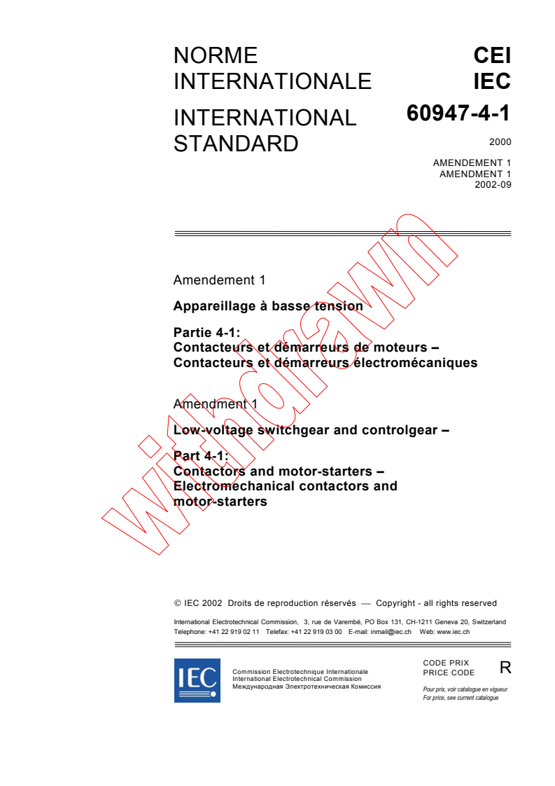
NORME CEI
INTERNATIONALE IEC
60947-4-1
INTERNATIONAL
STANDARD
AMENDEMENT 1
AMENDMENT 1
2002-09
Amendement 1
Appareillage à basse tension
Partie 4-1:
Contacteurs et démarreurs de moteurs –
Contacteurs et démarreurs électromécaniques
Amendment 1
Low-voltage switchgear and controlgear –
Part 4-1:
Contactors and motor-starters –
Electromechanical contactors and
motor-starters
IEC 2002 Droits de reproduction réservés Copyright - all rights reserved
International Electrotechnical Commission, 3, rue de Varembé, PO Box 131, CH-1211 Geneva 20, Switzerland
Telephone: +41 22 919 02 11 Telefax: +41 22 919 03 00 E-mail: inmail@iec.ch Web: www.iec.ch
CODE PRIX
R
Commission Electrotechnique Internationale
PRICE CODE
International Electrotechnical Commission
Международная Электротехническая Комиссия
Pour prix, voir catalogue en vigueur
For price, see current catalogue
– 2 – 60947-4-1 amend. 1 CEI:2002
AVANT-PROPOS
Le présent amendement a été établi par le sous-comité 17B: Appareillage à basse tension, du
comité d'études 17 de la CEI: Appareillage.
Le texte de cet amendement est issu des documents suivants:
FDIS Rapport de vote
17B/1210/FDIS 17B/1237/RVD
Le rapport de vote indiqué dans le tableau ci-dessus donne toute information sur le vote ayant
abouti à l'approbation de cet amendement.
Le comité a décidé que le contenu de la publication de base et de ses amendements ne sera
pas modifié avant 2005. A cette date, la publication sera
• reconduite;
• supprimée;
• remplacée par une édition révisée, ou
• amendée.
____________
Page 2
SOMMAIRE
Modifier, à la page 4, le titre de l'annexe C pour lire:
Annexe C Vacant
Ajouter, à la page 4, le titre des nouvelles annexes E et F et de la nouvelle bibliographie:
Annexe E (informative) Exemples de configuration de circuits de commande
Annexe F (normative) Prescriptions pour un contact auxiliaire lié à un contact de puissance
(contact miroir)
Bibliographie
Supprimer, à la page 6, la référence au tableau 11.
60947-4-1 Amend. 1 IEC:2002 – 3 –
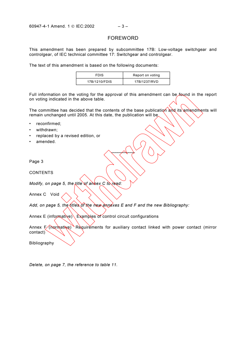
FOREWORD
This amendment has been prepared by subcommittee 17B: Low-voltage switchgear and
controlgear, of IEC technical committee 17: Switchgear and controlgear.
The text of this amendment is based on the following documents:
FDIS Report on voting
17B/1210/FDIS 17B/1237/RVD
Full information on the voting for the approval of this amendment can be found in the report
on voting indicated in the above table.
The committee has decided that the contents of the base publication and its amendments will
remain unchanged until 2005. At this date, the publication will be
• reconfirmed;
• withdrawn;
• replaced by a revised edition, or
• amended.
___________
Page 3
CONTENTS
Modify, on page 5, the title of annex C to read:
Annex C Void
Add, on page 5, the titles of the new annexes E and F and the new Bibliography:
Annex E (informative) Examples of control circuit configurations
Annex F (normative) Requirements for auxiliary contact linked with power contact (mirror
contact)
Bibliography
Delete, on page 7, the reference to table 11.
– 4 – 60947-4-1 amend. 1 CEI:2002
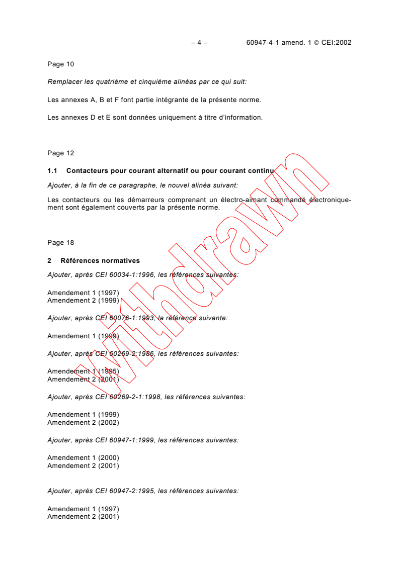
Page 10
Remplacer les quatrième et cinquième alinéas par ce qui suit:
Les annexes A, B et F font partie intégrante de la présente norme.
Les annexes D et E sont données uniquement à titre d’information.
Page 12
1.1 Contacteurs pour courant alternatif ou pour courant continu
Ajouter, à la fin de ce paragraphe, le nouvel alinéa suivant:
Les contacteurs ou les démarreurs comprenant un électro-aimant commandé électronique-
ment sont également couverts par la présente norme.
Page 18
2 Références normatives
Ajouter, après CEI 60034-1:1996, les références suivantes:
Amendement 1 (1997)
Amendement 2 (1999)
Ajouter, après CEI 60076-1:1993, la référence suivante:
Amendement 1 (1999)
Ajouter, après CEI 60269-2:1986, les références suivantes:
Amendement 1 (1995)
Amendement 2 (2001)
Ajouter, après CEI 60269-2-1:1998, les références suivantes:
Amendement 1 (1999)
Amendement 2 (2002)
Ajouter, après CEI 60947-1:1999, les références suivantes:
Amendement 1 (2000)
Amendement 2 (2001)
Ajouter, après CEI 60947-2:1995, les références suivantes:
Amendement 1 (1997)
Amendement 2 (2001)
60947-4-1 Amend. 1 IEC:2002 – 5 –
Page 11
Replace both fourth and fifth paragraphs by the following:
Annexes A, B and F form an integral part of this standard.
Annexes D and E are for information only.
Page 13
1.1 AC and d.c. contactors
Add, at the end of this subclause, the following new paragraph:
Contactors or starters with an electronically controlled electromagnet are also covered by this
standard.
Page 19
2 Normative references
Add, after IEC 60034-1:1996, the following references:
Amendment 1 (1997)
Amendment 2 (1999)
Add, after IEC 60076-1:1993, the following reference:
Amendment 1 (1999)
Add, after IEC 60269-2:1986, the following references:
Amendment 1 (1995)
Amendment 2 (2001)
Add, after IEC 60269-2-1:1998, the following references:
Amendment 1 (1999)
Amendment 2 (2002)
Add, after IEC 60947-1:1999, the following references:
Amendment 1 (2000)
Amendment 2 (2001)
Add, after IEC 60947-2:1995, the following references:
Amendment 1 (1997)
Amendment 2 (2001)
– 6 – 60947-4-1 amend. 1 CEI:2002
Ajouter, après CEI 60947-3:1999, la référence suivante:
Amendement 1 (2001)
Ajouter, après CEI 60947-5-1:1997, les références suivantes:
Amendement 1 (1999)
Amendement 2 (1999)
Ajouter, après CEI 61000-4-2:1995, les références suivantes:
Amendement 1 (1998)
Amendement 2 (2000)
Ajouter, après CEI 61000-4-3:1995, les références suivantes:
Amendement 1 (1998)
Amendement 2 (2000)
Ajouter, après CEI 61000-4-4:1995, les références suivantes:
Amendement 1 (2000)
Amendement 2 (2001)
Ajouter, après CEI 61000-4-5:1995, la référence suivante:
Amendement 1 (2000)
Ajouter, après CEI 61095:1992, la référence suivante:
Amendement 1 (2000)
Ajouter, après CISPR 11:1997, la référence suivante:
Amendement 1 (1999)
Page 22
3.1.2
contacteur électromagnétique
Ajouter, après la définition, la note suivante:
NOTE L'électro-aimant peut être commandé électroniquement (voir 3.1.8).
60947-4-1 Amend. 1 IEC:2002 – 7 –
Add, after IEC 60947-3:1999, the following reference:
Amendment 1 (2001)
Add, after IEC 60947-5-1:1997, the following references:
Amendment 1 (1999)
Amendment 2 (1999)
Add, after IEC 61000-4-2:1995, the following references:
Amendment 1 (1998)
Amendment 2 (2000)
Add, after IEC 61000-4-3:1995, the following references:
Amendment 1 (1998)
Amendment 2 (2000)
Add, after IEC 61000-4-4:1995, the following references:
Amendment 1 (2000)
Amendment 2 (2001)
Add, after IEC 61000-4-5:1995, the following reference:
Amendment 1 (2000)
Add, after IEC 61095:1992, the following reference:
Amendment 1 (2000)
Add, after CISPR 11:1997, the following reference:
Amendment 1 (1999)
Page 23
3.1.2
electromagnetic contactor
Add, after the definition, the following note:
NOTE The electromagnet may be electronically controlled (see 3.1.8).
– 8 – 60947-4-1 amend. 1 CEI:2002
Ajouter, après 3.1.7, la nouvelle définition 3.1.8 suivante:
3.1.8
bobine commandée électroniquement pour électro-aimant
bobine commandée par un circuit comprenant des éléments électroniques actifs
Page 50
5.5 Circuits de commande
Remplacer le texte existant par ce qui suit:
Le paragraphe 4.5 de la CEI 60947-1 est applicable; de plus, pour un électro-aimant
commandé électroniquement, 4.5.1 de la CEI 60947-1 est applicable avec le complément qui
suit.
La partie électronique peut faire partie intégrante ou être une partie séparée à condition
qu'elle soit une fonction intrinsèque de l'appareil. Dans les deux cas, l'appareil doit être
essayé avec cette partie électronique montée comme en usage normal.
Les caractéristiques des circuits électroniques de commande sont celles qui suivent:
− la nature du courant;
− la consommation d'énergie;
− la fréquence assignée (ou à courant continu);
− la tension assignée des circuits de commande, U (nature: courant alternatif/courant
c
continu);
− la tension assignée d'alimentation de commande, U (nature: courant alternatif/courant
s
continu);
− la nature des dispositifs externes du circuit de commande (contacts, capteurs,
optocoupleurs, composants électroniques actifs, etc.).
L'annexe E donne des exemples et des illustrations de différentes configurations de circuit.
NOTE Une distinction est faite entre la tension du circuit de commande U , qui est le signal de commande
c
d'entrée, et la tension d'alimentation de commande U , qui est la tension à appliquer pour alimenter les bornes
s
d'alimentation du circuit de commande du matériel, et qui peut être différente de U en raison de la présence
c
d'appareils incorporés tels que transformateurs, redresseurs, résistances, circuits électroniques, etc.
Page 56
5.8 Coordination avec les dispositifs de protection contre les courts-circuits
Remplacer le texte existant par ce qui suit:
La coordination des contacteurs et des démarreurs est caractérisée par le type, les grandeurs
assignées et les caractéristiques des dispositifs de protection contre les courts-circuits
(DPCC) qui assurent une protection du contacteur et du démarreur contre les courants de
court-circuit. Les prescriptions sont données en 8.2.5.1 et 8.2.5.2 de la présente norme et en
4.8 de la CEI 60947-1.
60947-4-1 Amend. 1 IEC:2002 – 9 –
Add, after 3.1.7, the following new definition 3.1.8:
3.1.8
electronically controlled coil for electromagnet
coil controlled by a circuit with active electronic elements
Page 51
5.5 Control circuits
Replace the existing text by the following:
Subclause 4.5 of IEC 60947-1 applies; moreover, for an electronically controlled electro-
magnet, 4.5.1 of IEC 60947-1 applies with the following addition.
The electronic part may form an integral part or a separate part provided it is an intrinsic
function of the device. In both cases, the device shall be tested with this electronic part
mounted as in normal use.
The characteristics of electronic control circuits are as follows:
− type of current;
− power consumption;
− rated frequency (or d.c.);
− rated control circuit voltage, U (nature: a.c./d.c.);
c
− rated control supply voltage, U (nature: a.c./d.c.);
s
− nature of external control circuit devices (contacts, sensors, optocouplers, electronic
active components, etc).
Annex E gives examples and illustrations of different circuit configurations.
NOTE A distinction is made between the control circuit voltage U , which is the controlling input signal, and the
c
control supply voltage U , which is the voltage applied to energize the power supply terminals of the control circuit
s
equipment and may be different from U due to the presence of built-in transformers, rectifiers, resistors, electronic
c
circuitry, etc.
Page 57
5.8 Co-ordination with short-circuit protective devices
Replace the existing text by the following:
The co-ordination of contactors and starters is characterized by the type, ratings and
characteristics of the short-circuit protective devices (SCPD) that provide protection of the
contactor and starter against short-circuit currents. Requirements are given in 8.2.5.1 and
8.2.5.2 of this standard, and in 4.8 of IEC 60947-1.
– 10 – 60947-4-1 amend. 1 CEI:2002
Page 60
6.1.2 Caractéristiques, valeurs assignées fondamentales et utilisation
Remplacer le point j) existant par le nouveau point j) suivant:
j) tension assignée de tenue aux chocs (voir 5.3.1.3);
Remplacer, à la page 62, le point y) existant par le nouveau point y) suivant:
y) environnement A ou B: voir 7.3.1 de la CEI 60947-1;
Page 62
6.2 Marquage
Ajouter, après le troisième alinéa, le nouvel alinéa suivant:
Dans le cas d'électro-aimants commandés électroniquement, d'autres informations que celles
données en o) et en p) de 6.1.2 peuvent aussi être nécessaires; voir aussi 5.5 et l'annexe E.
Page 64
8.1.3 Distances d'isolement et lignes de fuite
Remplacer le texte existant par ce qui suit:
Le paragraphe 7.1.3 de la CEI 60947-1 est applicable.
8.1.6 Prescriptions supplémentaires de sécurité pour les matériels ayant une fonction
de sectionnement
Remplacer le texte existant par ce qui suit:
Le paragraphe 7.1.6 de la CEI 60947-1 est applicable avec l'addition, en 7.1.6.1 de la norme
précitée, des alinéas suivants.
Les appareils pourvus de positions, comme une position déclenchée ou une position
d’attente, qui ne sont pas la position d'ouverture indiquée doivent être marqués sans
ambiguïté.
Un organe de commande qui n'a qu'une seule position de repos ne doit pas être considéré
comme approprié pour indiquer la position des contacts principaux.
60947-4-1 Amend. 1 IEC:2002 – 11 –
Page 61
6.1.2 Characteristics, basic rated values and utilization
Replace the existing item j) by the following new item j):
j) rated impulse withstand voltage (see 5.3.1.3);
Replace, on page 63, the existing item y) by the following new item y):
y) environment A or B: see 7.3.1 of IEC 60947-1;
Page 63
6.2 Marking
Add, after the third paragraph, the following new paragraph:
In the case of electronically controlled electromagnets, information other than that given in o)
and p) of 6.1.2 may also be necessary; see also 5.5 and annex E.
Page 65
8.1.3 Clearances and creepage distances
Replace the existing text by the following:
Subclause 7.1.3 of IEC 60947-1 applies.
8.1.6 Additional safety requirements for equipment with isolating function
Replace the existing text by the following:
Subclause 7.1.6 of IEC 60947-1 applies with the addition of the following paragraphs to
subclause 7.1.6.1 of that standard.
Devices provided with positions like trip position or stand-by position which are not the
indicated open position shall be clearly marked.
An actuator having only one position of rest shall not be considered as appropriate to indicate
the position of the main contact.
– 12 – 60947-4-1 amend. 1 CEI:2002
Page 68
8.2.1.2 Limites de fonctionnement des contacteurs et des démarreurs à manœuvre par
source d'énergie extérieure
Remplacer le texte existant de ce paragraphe par ce qui suit:
8.2.1.2.1 Contacteurs et démarreurs électromagnétiques
Qu'ils soient utilisés séparément ou avec des démarreurs, les contacteurs électromagnétiques
doivent se fermer de manière satisfaisante pour toute valeur de la tension d'alimentation de
commande U entre 85 % et 110 % de la valeur assignée de celle-ci. Lorsqu'une gamme de
s
tensions est indiquée, la valeur de 85 % s'applique à la valeur inférieure de cette gamme et la
valeur de 110 % s'applique à la valeur supérieure.
Les limites entre lesquelles les contacteurs doivent relâcher leurs contacts et s'ouvrir
complètement sont de 75 % à 20 % de la tension assignée d'alimentation de commande U
s
pour le courant alternatif et de 75 % à 10 % de celle-ci pour le courant continu. Lorsqu'une
gamme de tensions est indiquée, les valeurs de 20 % ou de 10 %, selon le cas, s'appliquent à
la valeur supérieure de cette gamme et la valeur de 75 % à la valeur inférieure.
Les valeurs limites pour la fermeture sont valables après que les bobines aient atteint une
température stable correspondant à l'application indéfinie de 100 % U à une température
s
ambiante équivalente à la température ambiante déclarée par le constructeur mais non
inférieure à +40 °C.
Les valeurs limites pour la retombée sont valables lorsque la résistance du circuit de la
bobine est égale à celle obtenue à –5 °C. Cela peut être vérifié par calcul en se servant des
valeurs obtenues à la température normale de l’air ambiant.
Ces limites sont valables en courant continu et en courant alternatif à la fréquence indiquée.
8.2.1.2.2 Contacteurs et démarreurs avec électro-aimant commandé électroniquement
Le paragraphe 8.2.1.2.1 est applicable avec la modification suivante.
Remplacer le deuxième alinéa par ce qui suit:
Les limites entre lesquelles les contacteurs avec électro-aimant commandé électroniquement
doivent relâcher leurs contacts et s'ouvrir complètement sont
− pour le courant continu: 75 % à 10 % de la tension assignée d'alimentation de commande
U ,
s
− pour le courant alternatif: 75 % à 20 % de la tension assignée d'alimentation de
commande U ,
s
− pour le courant alternatif: 75 % à 10 % de la tension assignée d'alimentation de
commande U si cela est spécifié par le constructeur,
s
− pour le courant alternatif, lorsqu'une gamme de tensions est indiquée avec des limites
comprises entre 75 % et 10 % de la tension assignée d'alimentation de commande U , le
s
contacteur doit, de plus, être soumis à l'essai de retombée sur ligne capacitive de
8.2.1.2.4.
Lorsqu'une gamme de tensions est indiquée, les valeurs de 20 % ou de 10 %, selon le cas,
s'appliquent à la valeur supérieure de cette gamme et la valeur de 75 % à la valeur inférieure.
60947-4-1 Amend. 1 IEC:2002 – 13 –
Page 69
8.2.1.2 Limits of operation of contactors and power-operated starters
Replace the existing text of this subclause as follows:
8.2.1.2.1 Electromagnetic contactors and starters
Electromagnetic contactors, whether used separately or in starters, shall close satisfactorily at
any value between 85 % and 110 % of their rated control supply voltage U . Where a range is
s
declared, 85 % shall apply to the lower value and 110 % to the higher.
The limits between which contactors shall drop out and open fully are 75 % to 20 % for a.c.
and 75 % to 10 % for d.c. of their rated control supply voltage U . Where a range is declared,
s
20 % or 10 %, as the case may be, shall apply to the higher value and 75 % to the lower.
Limits for closing are applicable after the coils have reached a stable temperature
corresponding to indefinite application of 100 % U in an ambient temperature equivalent to
s
the ambient temperature declared by the manufacturer but not less than +40 °C.
Limits for drop-out are applicable with the coil circuit resistance at −5 °C. This can be verified
by calculation using values obtained at normal ambient air temperature.
The limits apply to d.c. and a.c. at declared frequency.
8.2.1.2.2 Contactors and starters with electronically controlled electromagnet
Subclause 8.2.1.2.1 applies with the following modification.
Replace the second paragraph as follows:
The limits between which contactors with an electronically controlled electromagnet shall drop
out and open fully are
− for d.c.: 75 % to 10 % of their rated control supply voltage U
s,
− for a.c.: 75 % to 20 % of their rated control supply voltage U ,
s
− for a.c.: 75 % to 10 % of their rated control supply voltage U if specified by the
s
manufacturer,
− for a.c., where a range is declared with limits between 75 % to 10 % of their rated control
supply voltage U , the contactor shall, in addition, be submitted to the capacitive drop out
s
test of 8.2.1.2.4.
Where a range is declared, 20 % or 10 % as the case may be, shall apply to the higher value
of the range and 75 % to the lower value of the range.
– 14 – 60947-4-1 amend. 1 CEI:2002
8.2.1.2.3 Contacteurs et démarreurs électropneumatiques
La fermeture des contacteurs électropneumatiques et pneumatiques doit être assurée de
façon satisfaisante pour toute valeur de la pression d'alimentation comprise entre 85 % et
110 % de la valeur assignée, et leur ouverture pour toute valeur de pression comprise entre
75 % et 10 % de la valeur assignée.
8.2.1.2.4 Essai de retombée sur ligne capacitive
Un condensateur C doit être inséré en série dans le circuit d'alimentation U , la longueur
s
totale des conducteurs de raccordement étant inférieure ou égale à 3 m. Le condensateur est
court-circuité par un interrupteur d'impédance négligeable. La tension d'alimentation doit alors
être réglée à 110 % U .
s
Il doit être vérifié que le contacteur retombe lorsque l'interrupteur est placé en position
ouverte.
La valeur du condensateur doit être
C (nF) = 30 + 200 000 / (f × U )
s
par exemple, pour une bobine de tension assignée 12…24 V – 50 Hz, la valeur du
condensateur est 196 nF (le calcul est fait avec U max., voir note 1).
s
NOTE 1 La tension d'essai est la valeur la plus élevée de la gamme de tensions assignées d'alimentation
déclarée U .
s
NOTE 2 La valeur du condensateur est calculée dans le but de simuler un câble de 1,5 mm de section et d'une
longueur de 100 m raccordé à une sortie statique ayant un courant de fuite de 1,3 mA.
NOTE 3 Il convient que le temps de retombée soit spécifié pour les utilisations particulières, par exemple coupure
d’urgence.
Page 70
8.2.1.5.1 Limites de fonctionnement des relais de surcharge temporisés quand
tous leurs pôles sont alimentés
Remplacer, au point c), "… 18.2 de la CEI 60034-1;" par "…8.2.3 de la CEI 60034-1;"
Page 74
8.2.2 Echauffement
Insérer, après le deuxième alinéa, le nouvel alinéa suivant:
Dans le cas d'un électro-aimant commandé électroniquement, la mesure de température de la
bobine par variation de résistance peut être impraticable; dans un tel cas, d'autres méthodes
sont autorisées, par exemple, thermocouples ou toute autre méthode appropriée.
60947-4-1 Amend. 1 IEC:2002 – 15 –
8.2.1.2.3 Electro-pneumatic contactors and starters
Electro-pneumatic and pneumatic contactors shall close satisfactorily with the air supply
pressure between 85 % and 110 % of the rated pressure and open between 75 % and 10 % of
the rated pressure.
8.2.1.2.4 Capacitive drop out test
A capacitor C shall be inserted in series in the supply circuit U , the total length of the
s
connecting conductors being ≤3 m. The capacitor is short-circuited by a switch of negligible
impedance. The supply voltage shall then be adjusted to 110 % U .
s
It shall be verified that the contactor drops out when the switch is operated to the open
position.
The value of the capacitor shall be
C (nF) = 30 + 200 000 / (f × U )
s
e.g. for a coil rated 12…24 V – 50 Hz, the capacitor value is 196 nF (calculation made with U
s
max., see note 1).
NOTE 1 The test voltage is the highest value of the declared rated supply voltage range U .
s
NOTE 2 The value of the capacitor is calculated in order to simulate a 100 m long cable of 1,5 mm connected to
a static output having a 1,3 mA leakage current.
NOTE 3 The drop out time should be specified for particular uses, e.g. emergency breaking.
Page 71
8.2.1.5.1 Limits of operation of time-delay overload relays when all poles are energized
Replace, in item c), the phrase ". 18.2 of IEC 60034-1." by ". 8.2.3 of IEC 60034-1;"
Page 75
8.2.2 Temperature rise
Insert, after the second paragraph, the following new paragraph:
In the case of an electronically controlled electromagnet, coil temperature measuring by
variation of resistance may be impracticable; in such a case, other methods are permitted,
e.g. thermocouples or other suitable methods.
– 16 – 60947-4-1 amend. 1 CEI:2002
Page 76
8.2.2.6.1 Enroulements pour service ininterrompu et service de 8 h
Ajouter, à la fin de ce paragraphe, la note suivante:
NOTE Selon la technologie, par exemple pour certains électro-aimants commandés électroniquement, la tension
d'alimentation de commande peut ne pas être appliquée directement sur les enroulements de la bobine raccordée
comme en service normal.
8.2.2.6.2 Enroulements pour service intermittent
Ajouter, après le premier alinéa, la note suivante:
NOTE Selon la technologie, par exemple pour certains électro-aimants commandés électroniquement, la tension
d'alimentation de commande peut ne pas être appliquée directement sur les enroulements de la bobine raccordée
comme en service normal.
8.2.3 Propriétés diélectriques
Remplacer le texte existant par ce qui suit:
Le paragraphe 7.2.3 de la CEI 60947-1 est applicable.
Page 90
8.3.3 Emission
Remplacer, dans le premier alinéa, «environnement 1» par «environnement B» et
«environnement 2» par «environnement A».
Page 92
9.1.3 Essais individuels (voir 9.3.6)
Remplacer le titre existant par ce qui suit:
9.1.3 Essais individuels
9.1.4 Essais sur prélèvement (voir 9.3.6)
Remplacer le titre existant par ce qui suit:
9.1.4 Essais sur prélèvement
Remplacer le texte existant du dernier alinéa par ce qui suit:
Les essais sur prélèvement pour la vérification des distances d'isolement doivent être
effectués selon 8.3.3.4.3 de la CEI 60947-1.
60947-4-1 Amend. 1 IEC:2002 – 17 –
Page 77
8.2.2.6.1 Uninterrupted and eight-hour duty windings
Add, at the end of this subclause, the following note:
NOTE Depending on the technology, e.g. for some kinds of electronically controlled electromagnets, the control
supply voltage may not be directly applied on the coil winding when connected as in normal service.
8.2.2.6.2 Intermittent duty windings
Add, after the first paragraph, the following note:
NOTE Depending on the technology, e.g. for some kind of electronically controlled electromagnet, the control
supply voltage may not be directly applied on the coil winding when connected as in normal service.
8.2.3 Dielectric properties
Replace the existing text by the following:
Subclause 7.2.3 of IEC 60947-1 applies.
Page 91
8.3.3 Emission
Replace, in the first paragraph, “environment 1” by “environment B” and “environment 2” by
“environment A”.
Page 93
9.1.3 Routine tests (see 9.3.6)
Replace the existing title by the following:
9.1.3 Routine tests
9.1.4 Sampling tests (see 9.3.6)
Replace the existing title by the following:
9.1.4 Sampling tests
Replace the existing text of the last paragraph by the following:
Sampling tests for clearance verification shall be performed according to 8.3.3.4.3 of
IEC 60947-1.
– 18 – 60947-4-1 amend. 1 CEI:2002
Page 98
9.3.3.2.2 Relais et déclencheurs
Remplacer le troisième alinéa de c), commençant par " En outre, les caractéristiques…" par
ce qui suit:
En outre, les caractéristiques définies en 8.2.1.5.1 doivent être vérifiées par des essais à
−5 °C, +20 °C, +40 °C et peuvent être vérifiées aux températures maximale et minimale
indiquées par le constructeur si celles-ci sont plus étendues. Cependant, pour les relais ou
déclencheurs déclarés compensés pour la température ambiante dont le domaine de
température déclaré par le constructeur est plus étendu que celui donné à la figure 7, il n’est
pas nécessaire de vérifier les caractéristiques à −5 °C et/ou +40 °C dans le cas où elles ont
été vérifiées aux températures minimale et maximale déclarées et que les valeurs
correspondantes de courant de déclenchement sont à l’intérieur des limites spécifiées dans
cette figure pour −5 °C et/ou +40 °C.
Page 102
9.3.3.4 Propriétés diélectriques
Remplacer le texte existant et les paragraphes 9.3.3.4.1 à 9.3.3.4.4 existants par ce qui suit:
Le paragraphe 8.3.3.4 de la CEI 60947-1 est applicable avec les modifications suivantes.
9.3.3.4.1 Essais de type
Le paragraphe 8.3.3.4.1 de la CEI 60947-1 est applicable avec l'addition
− des phrases suivantes, à la fin du point 1):
La feuille métallique doit être appliquée sur toutes les surfaces là où celles-ci risquent
d'être touchées par des personnes pendant le fonctionnement normal ou le réglage du
matériel, et lorsque de telles surfaces peuvent être aussi touchées avec le doigt
d'épreuve normalisé.
La feuille métallique ne doit pas être appliquée pour la vérification de la tenue à
fréquence industrielle après les essais de commutation et de court-circuit.
− de la phrase suivante, après le deuxième alinéa du point 2) b):
Les circuits d'un contacteur ou d'un démarreur comprenant des dispositifs qui ont été
soumis à des tensions d'essai U inférieures à celles spécifiées en 7.2.3.1 et en
imp
8.3.3.4.2 de la CEI 60947-1 peuvent être déconnectés pour l'essai, selon les
instructions du constructeur.
− de la phrase suivante, après l'alinéa du point 2) c) ii):
Lorsque le circuit de commande normalement raccordé au circuit principal est
déconnecté (conformément à 8.3.3.4.1, point 2) b)), la méthode utilisée pour maintenir
les contacts principaux fermés doit être indiquée dans le rapport d'essai.
− de la phrase suivante, à la fin de 8.3.3.4.1, point 8)
...