


IEC 62217:2025
(Main)Polymeric HV insulators for indoor and outdoor use - General definitions, test methods and acceptance criteria
General Information
- Abstract
IEC 62217:2025 is applicable to polymeric insulators for AC systems with a nominal voltage greater than 1 000 V (frequency less than 100 Hz) and DC systems with a nominal voltage greater than 1 500 V whose insulating body consists of one or various organic materials. Polymeric insulators covered by this document are intended for use both on HV overhead lines and in substations, in both indoor and outdoor applications. They include composite insulators with solid and hollow core and resin insulators. Hybrid insulators with ceramic core and polymeric housing are also included, while coated insulators (e.g. with RTV silicone rubber coatings) are not included in this standard. Electrical tests described in this document are done under AC voltage and are in general applicable to insulators to be used in DC systems too. Tests under DC voltage are intended to reflect up-to-date knowledge and experience. Only polymeric housing materials of hybrid insulators are specified in this document. Tests for core materials and the interfaces between housing and core of hybrid insulators are not included.
The object of this document is
- to define the common terms used for polymeric insulators;
- to prescribe common test methods for design tests on polymeric insulators;
- to prescribe acceptance or failure criteria, if applicable;
These tests, criteria and recommendations are intended to ensure a satisfactory lifetime under normal operating and environmental conditions. This document includes design tests intended to reject materials or designs which are inadequate under normal operating and environmental conditions. This document defines test methods and acceptance criteria. The applicable tests are given in the relevant product standard. This third edition cancels and replaces the second edition published in 2012. This edition constitutes a technical revision.
This edition includes the following significant technical changes with respect to the previous edition:
a) The scope of the document is specified to comprise composite insulators with solid and hollow core and resin insulators used for both AC and DC systems in indoor and outdoor applications of HV overhead lines and substations; hybrid insulators (defined in IEC TS 62896) with ceramic core and polymeric housing are also included, while coated insulators (e.g. with Room Temperature Vulcanized (RTV) silicone rubber coatings) are not considered in this document;
b) Steep-front impulse voltage test is modified to avoid unwanted flashovers between the leads of the electrodes;
c) Differences between hydrophobicity transfer material (HTM) and non-HTM housing materials are specified and relevant test methods and acceptance criteria for polymeric insulators with HTM housing are introduced;
d) The previous water diffusion test on core materials with or without housing is split into two tests. One is on core materials without housing, the other is on core materials with housing. The acceptance criteria are modified;
e) Stress corrosion test for core materials is introduced;
f) Annex B summarizes the test application for evaluating the quality of interfaces and connections of end fittings, housing materials and core materials;
g) Annex E is introduced to emphasize the need for control of electric fields of polymeric insulators for AC. The control of electric fields of polymeric insulators for DC is still under consideration.
- Status
- Published
- Publication Date
- 05-Oct-2025
- Technical Committee
- TC 36 - Insulators
- Drafting Committee
- MT 19 - TC 36/MT 19
- Current Stage
- PPUB - Publication issued
- Start Date
- 06-Oct-2025
- Completion Date
- 03-Oct-2025
Buy Documents
IEC 62217:2025 - Polymeric HV insulators for indoor and outdoor use - General definitions, test methods and acceptance criteria/6/2025
REDLINE IEC 62217:2025 CMV - Polymeric HV insulators for indoor and outdoor use - General definitions, test methods and acceptance criteria Released:10/6/2025
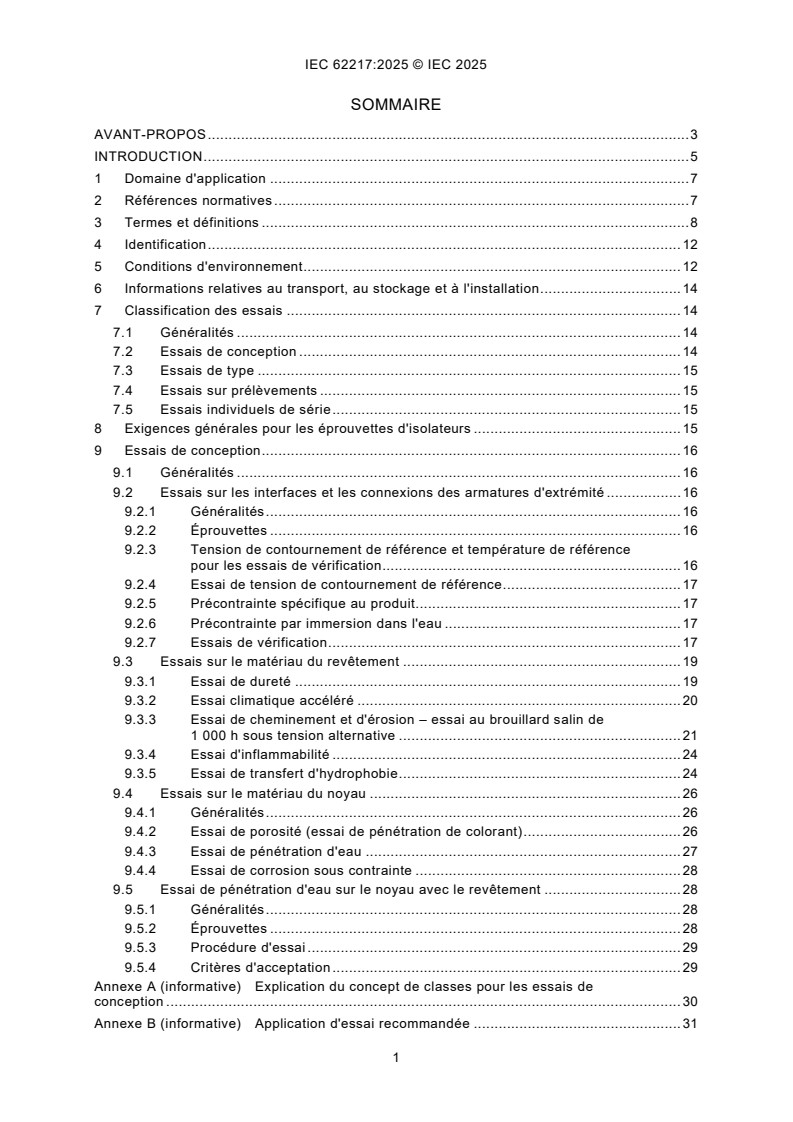
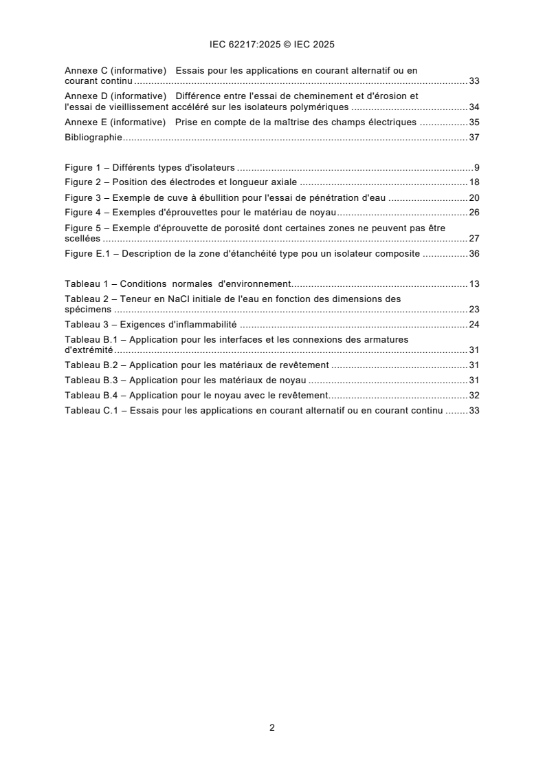
IEC 62217:2025 - Isolateurs polymériques à haute tension pour usage intérieur et extérieur - Définitions générales, méthodes d'essai et critères d'acceptation/6/2025
IEC 62217:2025 - Polymeric HV insulators for indoor and outdoor use - General definitions, test methods and acceptance criteria/6/2025
Overview
IEC 62217:2025 - "Polymeric HV insulators for indoor and outdoor use - General definitions, test methods and acceptance criteria" is the international standard that defines common terminology, design test methods and acceptance criteria for polymeric high-voltage (HV) insulators. It applies to polymeric insulators for AC systems with nominal voltage > 1 000 V (frequency < 100 Hz) and DC systems with nominal voltage > 1 500 V whose insulating body is made of organic materials. Covered product types include composite insulators (solid and hollow core) and resin insulators; hybrid insulators with a ceramic core and polymeric housing are included only for their polymeric housing materials. Coated insulators (e.g., RTV-coated) and core material/interface tests for hybrids are excluded.
This third edition (2025) is a technical revision of the 2012 edition and updates scope, test procedures and acceptance criteria to reflect current HV AC/DC applications and material developments.
Key topics and technical requirements
- Scope & definitions: Common terms for polymeric insulators used across overhead lines and substations, indoor and outdoor.
- Classification of tests: Design, type, sample and routine tests with recommended application scenarios.
- Material and specimen requirements: Test specimen preparation and environmental conditioning for realistic ageing and performance evaluation.
- Electrical testing: AC-based electrical tests (generally applicable to DC use); updated procedures for steep-front impulse voltage tests to avoid unwanted electrode flashovers.
- Material-specific tests: Tracking and erosion, accelerated weathering, hardness, flammability, porosity (dye penetration), and water diffusion (now split into core-only and core-with-housing tests).
- Hydrophobicity: Distinction between hydrophobicity transfer material (HTM) and non-HTM housings; introduced test methods and acceptance criteria for HTM housings.
- Mechanical and interface evaluation: Annex B provides guidance for evaluating end-fitting interfaces, housing–core connections and related pre-stressing/immersion procedures.
- New tests: Stress corrosion test for core materials; enhanced acceptance criteria and electric field control considerations (Annex E for AC; DC under review).
Practical applications
- Use IEC 62217:2025 to:
- Specify procurement and acceptance criteria for polymeric HV insulators.
- Develop product test programs and type-test reports for manufacturers.
- Guide independent test laboratories and certification bodies performing design and routine tests.
- Inform utilities and asset managers assessing insulator selection, lifecycle risk and field performance.
- Ensures consistent evaluation to achieve satisfactory lifetime under typical operating and environmental conditions.
Who should use this standard
- Insulator manufacturers, design engineers, test laboratories, utilities, procurement/specification teams, certification bodies and regulatory authorities involved in HV insulation selection, testing and compliance.
Related standards
- IEC TS 62896 (definition and aspects of hybrid insulators) - referenced for hybrid insulator context.
- Relevant product and regional standards (see IEC 62217 product-specific references for applicable tests and criteria).
Relations
- Effective Date
- 05-Sep-2023
Buy Documents
IEC 62217:2025 - Polymeric HV insulators for indoor and outdoor use - General definitions, test methods and acceptance criteria/6/2025
REDLINE IEC 62217:2025 CMV - Polymeric HV insulators for indoor and outdoor use - General definitions, test methods and acceptance criteria Released:10/6/2025
IEC 62217:2025 - Isolateurs polymériques à haute tension pour usage intérieur et extérieur - Définitions générales, méthodes d'essai et critères d'acceptation/6/2025
IEC 62217:2025 - Polymeric HV insulators for indoor and outdoor use - General definitions, test methods and acceptance criteria/6/2025
Get Certified
Connect with accredited certification bodies for this standard

IMQ S.p.A. (Certification)
Italian electrical product certification.

SLG Prüf- und Zertifizierungs GmbH
German testing and certification body.

UL Solutions
Global safety science company with testing, inspection and certification.
Sponsored listings
Frequently Asked Questions
IEC 62217:2025 is a standard published by the International Electrotechnical Commission (IEC). Its full title is "Polymeric HV insulators for indoor and outdoor use - General definitions, test methods and acceptance criteria". This standard covers: IEC 62217:2025 is applicable to polymeric insulators for AC systems with a nominal voltage greater than 1 000 V (frequency less than 100 Hz) and DC systems with a nominal voltage greater than 1 500 V whose insulating body consists of one or various organic materials. Polymeric insulators covered by this document are intended for use both on HV overhead lines and in substations, in both indoor and outdoor applications. They include composite insulators with solid and hollow core and resin insulators. Hybrid insulators with ceramic core and polymeric housing are also included, while coated insulators (e.g. with RTV silicone rubber coatings) are not included in this standard. Electrical tests described in this document are done under AC voltage and are in general applicable to insulators to be used in DC systems too. Tests under DC voltage are intended to reflect up-to-date knowledge and experience. Only polymeric housing materials of hybrid insulators are specified in this document. Tests for core materials and the interfaces between housing and core of hybrid insulators are not included. The object of this document is - to define the common terms used for polymeric insulators; - to prescribe common test methods for design tests on polymeric insulators; - to prescribe acceptance or failure criteria, if applicable; These tests, criteria and recommendations are intended to ensure a satisfactory lifetime under normal operating and environmental conditions. This document includes design tests intended to reject materials or designs which are inadequate under normal operating and environmental conditions. This document defines test methods and acceptance criteria. The applicable tests are given in the relevant product standard. This third edition cancels and replaces the second edition published in 2012. This edition constitutes a technical revision. This edition includes the following significant technical changes with respect to the previous edition: a) The scope of the document is specified to comprise composite insulators with solid and hollow core and resin insulators used for both AC and DC systems in indoor and outdoor applications of HV overhead lines and substations; hybrid insulators (defined in IEC TS 62896) with ceramic core and polymeric housing are also included, while coated insulators (e.g. with Room Temperature Vulcanized (RTV) silicone rubber coatings) are not considered in this document; b) Steep-front impulse voltage test is modified to avoid unwanted flashovers between the leads of the electrodes; c) Differences between hydrophobicity transfer material (HTM) and non-HTM housing materials are specified and relevant test methods and acceptance criteria for polymeric insulators with HTM housing are introduced; d) The previous water diffusion test on core materials with or without housing is split into two tests. One is on core materials without housing, the other is on core materials with housing. The acceptance criteria are modified; e) Stress corrosion test for core materials is introduced; f) Annex B summarizes the test application for evaluating the quality of interfaces and connections of end fittings, housing materials and core materials; g) Annex E is introduced to emphasize the need for control of electric fields of polymeric insulators for AC. The control of electric fields of polymeric insulators for DC is still under consideration.
IEC 62217:2025 is applicable to polymeric insulators for AC systems with a nominal voltage greater than 1 000 V (frequency less than 100 Hz) and DC systems with a nominal voltage greater than 1 500 V whose insulating body consists of one or various organic materials. Polymeric insulators covered by this document are intended for use both on HV overhead lines and in substations, in both indoor and outdoor applications. They include composite insulators with solid and hollow core and resin insulators. Hybrid insulators with ceramic core and polymeric housing are also included, while coated insulators (e.g. with RTV silicone rubber coatings) are not included in this standard. Electrical tests described in this document are done under AC voltage and are in general applicable to insulators to be used in DC systems too. Tests under DC voltage are intended to reflect up-to-date knowledge and experience. Only polymeric housing materials of hybrid insulators are specified in this document. Tests for core materials and the interfaces between housing and core of hybrid insulators are not included. The object of this document is - to define the common terms used for polymeric insulators; - to prescribe common test methods for design tests on polymeric insulators; - to prescribe acceptance or failure criteria, if applicable; These tests, criteria and recommendations are intended to ensure a satisfactory lifetime under normal operating and environmental conditions. This document includes design tests intended to reject materials or designs which are inadequate under normal operating and environmental conditions. This document defines test methods and acceptance criteria. The applicable tests are given in the relevant product standard. This third edition cancels and replaces the second edition published in 2012. This edition constitutes a technical revision. This edition includes the following significant technical changes with respect to the previous edition: a) The scope of the document is specified to comprise composite insulators with solid and hollow core and resin insulators used for both AC and DC systems in indoor and outdoor applications of HV overhead lines and substations; hybrid insulators (defined in IEC TS 62896) with ceramic core and polymeric housing are also included, while coated insulators (e.g. with Room Temperature Vulcanized (RTV) silicone rubber coatings) are not considered in this document; b) Steep-front impulse voltage test is modified to avoid unwanted flashovers between the leads of the electrodes; c) Differences between hydrophobicity transfer material (HTM) and non-HTM housing materials are specified and relevant test methods and acceptance criteria for polymeric insulators with HTM housing are introduced; d) The previous water diffusion test on core materials with or without housing is split into two tests. One is on core materials without housing, the other is on core materials with housing. The acceptance criteria are modified; e) Stress corrosion test for core materials is introduced; f) Annex B summarizes the test application for evaluating the quality of interfaces and connections of end fittings, housing materials and core materials; g) Annex E is introduced to emphasize the need for control of electric fields of polymeric insulators for AC. The control of electric fields of polymeric insulators for DC is still under consideration.
IEC 62217:2025 is classified under the following ICS (International Classification for Standards) categories: 29.080.10 - Insulators. The ICS classification helps identify the subject area and facilitates finding related standards.
IEC 62217:2025 has the following relationships with other standards: It is inter standard links to IEC 62217:2012. Understanding these relationships helps ensure you are using the most current and applicable version of the standard.
IEC 62217:2025 is available in PDF format for immediate download after purchase. The document can be added to your cart and obtained through the secure checkout process. Digital delivery ensures instant access to the complete standard document.
Standards Content (Sample)
IEC 62217 ®
Edition 3.0 2025-10
INTERNATIONAL
STANDARD
Polymeric HV insulators for indoor and outdoor use - General definitions, test
methods and acceptance criteria
ICS 29.080.10 ISBN 978-2-8327-0690-9
All rights reserved. Unless otherwise specified, no part of this publication may be reproduced or utilized in any form or
by any means, electronic or mechanical, including photocopying and microfilm, without permission in writing from either
IEC or IEC's member National Committee in the country of the requester. If you have any questions about IEC copyright
or have an enquiry about obtaining additional rights to this publication, please contact the address below or your local
IEC member National Committee for further information.
IEC Secretariat Tel.: +41 22 919 02 11
3, rue de Varembé info@iec.ch
CH-1211 Geneva 20 www.iec.ch
Switzerland
About the IEC
The International Electrotechnical Commission (IEC) is the leading global organization that prepares and publishes
International Standards for all electrical, electronic and related technologies.
About IEC publications
The technical content of IEC publications is kept under constant review by the IEC. Please make sure that you have the
latest edition, a corrigendum or an amendment might have been published.
IEC publications search - IEC Products & Services Portal - products.iec.ch
webstore.iec.ch/advsearchform Discover our powerful search engine and read freely all the
The advanced search enables to find IEC publications by a publications previews, graphical symbols and the glossary.
variety of criteria (reference number, text, technical With a subscription you will always have access to up to date
committee, …). It also gives information on projects, content tailored to your needs.
replaced and withdrawn publications.
Electropedia - www.electropedia.org
The world's leading online dictionary on electrotechnology,
IEC Just Published - webstore.iec.ch/justpublished
Stay up to date on all new IEC publications. Just Published containing more than 22 500 terminological entries in English
details all new publications released. Available online and and French, with equivalent terms in 25 additional languages.
once a month by email. Also known as the International Electrotechnical Vocabulary
(IEV) online.
IEC Customer Service Centre - webstore.iec.ch/csc
If you wish to give us your feedback on this publication or
need further assistance, please contact the Customer
Service Centre: sales@iec.ch.
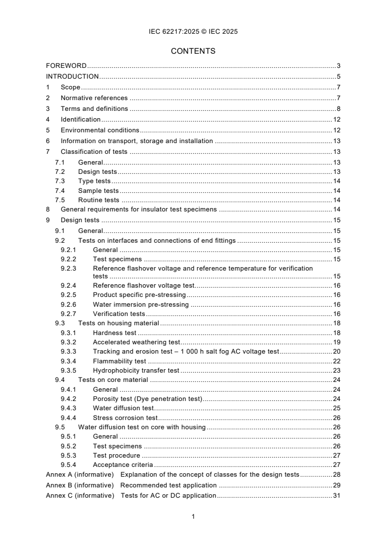
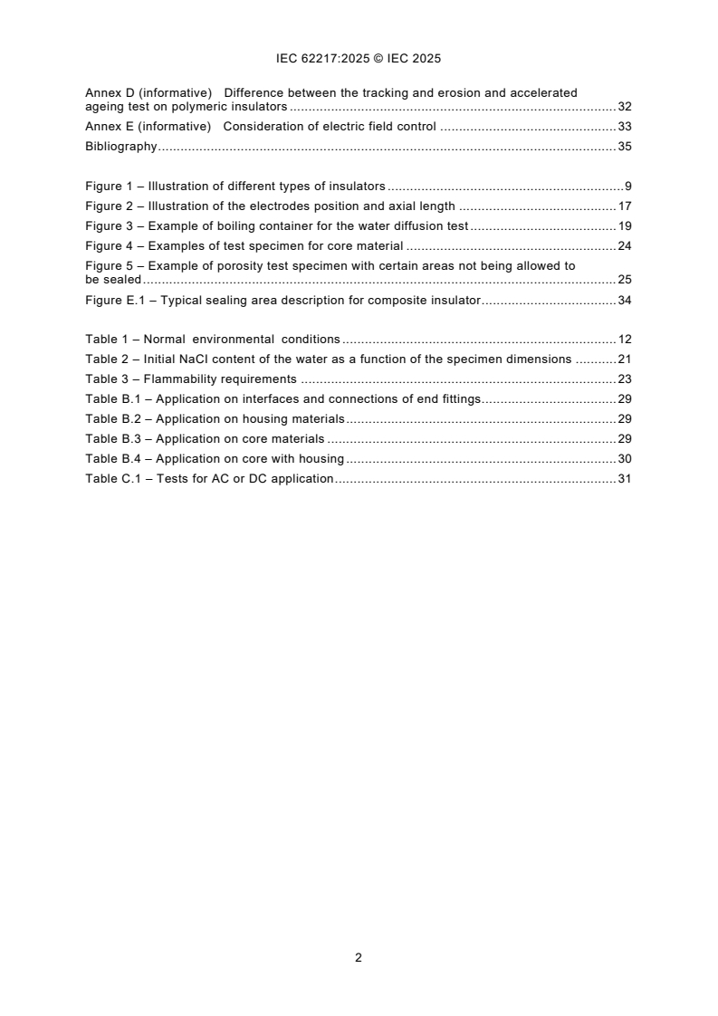
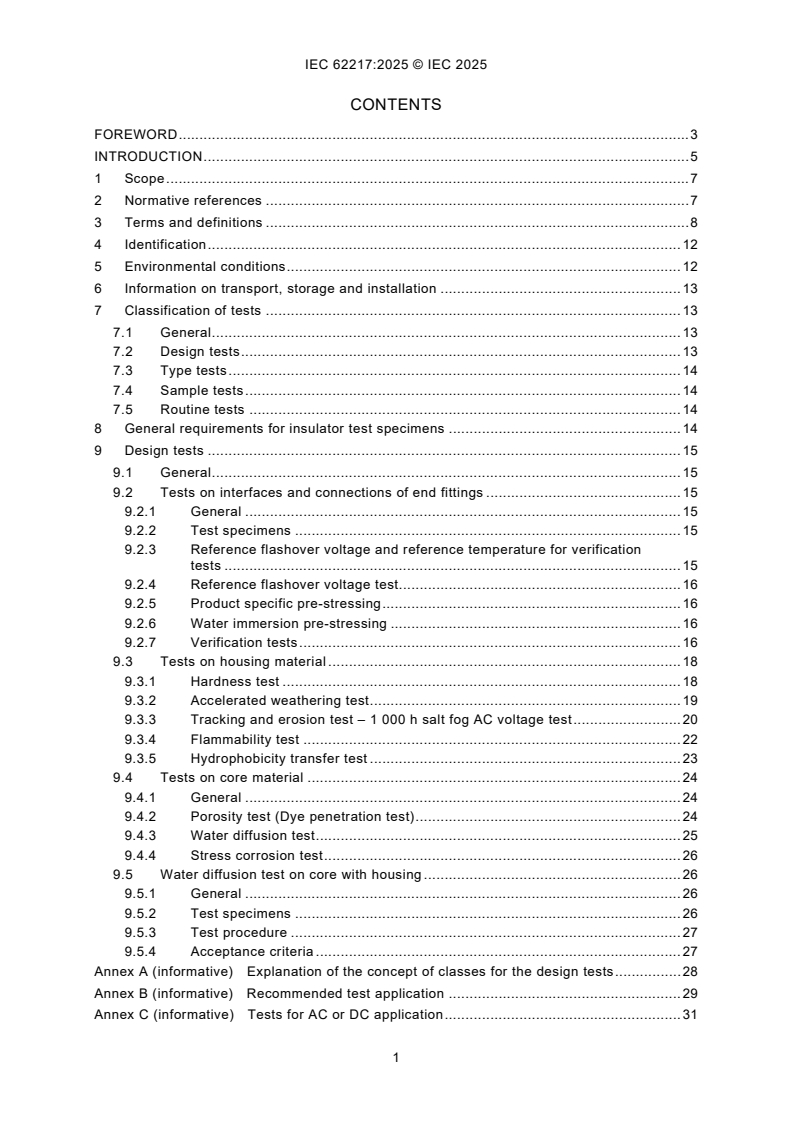
CONTENTS
FOREWORD . 3
INTRODUCTION . 5
1 Scope . 7
2 Normative references . 7
3 Terms and definitions . 8
4 Identification . 12
5 Environmental conditions . 12
6 Information on transport, storage and installation . 13
7 Classification of tests . 13
7.1 General . 13
7.2 Design tests . 13
7.3 Type tests . 14
7.4 Sample tests . 14
7.5 Routine tests . 14
8 General requirements for insulator test specimens . 14
9 Design tests . 15
9.1 General . 15
9.2 Tests on interfaces and connections of end fittings . 15
9.2.1 General . 15
9.2.2 Test specimens . 15
9.2.3 Reference flashover voltage and reference temperature for verification
tests . 15
9.2.4 Reference flashover voltage test. 16
9.2.5 Product specific pre-stressing . 16
9.2.6 Water immersion pre-stressing . 16
9.2.7 Verification tests . 16
9.3 Tests on housing material . 18
9.3.1 Hardness test . 18
9.3.2 Accelerated weathering test . 19
9.3.3 Tracking and erosion test – 1 000 h salt fog AC voltage test . 20
9.3.4 Flammability test . 22
9.3.5 Hydrophobicity transfer test . 23
9.4 Tests on core material . 24
9.4.1 General . 24
9.4.2 Porosity test (Dye penetration test) . 24
9.4.3 Water diffusion test . 25
9.4.4 Stress corrosion test . 26
9.5 Water diffusion test on core with housing . 26
9.5.1 General . 26
9.5.2 Test specimens . 26
9.5.3 Test procedure . 27
9.5.4 Acceptance criteria . 27
Annex A (informative) Explanation of the concept of classes for the design tests . 28
Annex B (informative) Recommended test application . 29
Annex C (informative) Tests for AC or DC application . 31
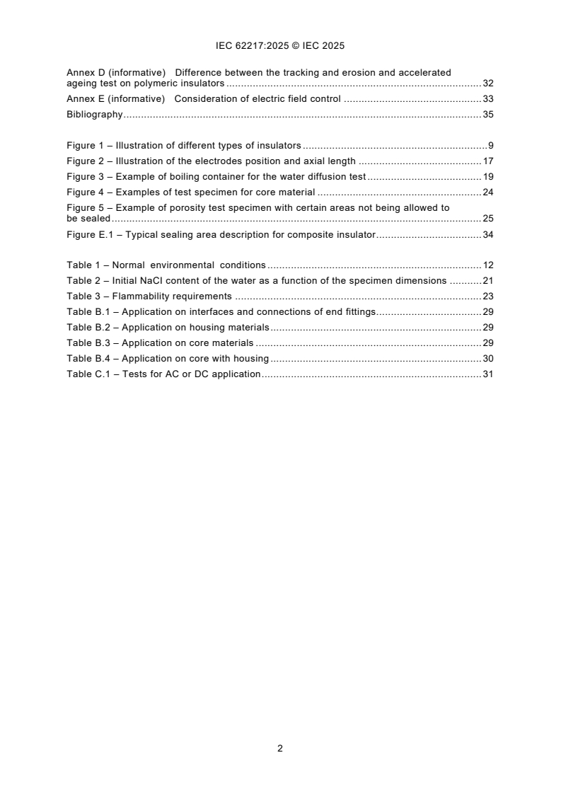
Annex D (informative) Difference between the tracking and erosion and accelerated
ageing test on polymeric insulators . 32
Annex E (informative) Consideration of electric field control . 33
Bibliography . 35
Figure 1 – Illustration of different types of insulators . 9
Figure 2 – Illustration of the electrodes position and axial length . 17
Figure 3 – Example of boiling container for the water diffusion test . 19
Figure 4 – Examples of test specimen for core material . 24
Figure 5 – Example of porosity test specimen with certain areas not being allowed to
be sealed . 25
Figure E.1 – Typical sealing area description for composite insulator . 34
Table 1 – Normal environmental conditions . 12
Table 2 – Initial NaCI content of the water as a function of the specimen dimensions . 21
Table 3 – Flammability requirements . 23
Table B.1 – Application on interfaces and connections of end fittings. 29
Table B.2 – Application on housing materials . 29
Table B.3 – Application on core materials . 29
Table B.4 – Application on core with housing . 30
Table C.1 – Tests for AC or DC application . 31
INTERNATIONAL ELECTROTECHNICAL COMMISSION
____________
Polymeric HV insulators for indoor and outdoor use -
General definitions, test methods and acceptance criteria
FOREWORD
1) The International Electrotechnical Commission (IEC) is a worldwide organization for standardization comprising
all national electrotechnical committees (IEC National Committees). The object of IEC is to promote international
co-operation on all questions concerning standardization in the electrical and electronic fields. To this end and
in addition to other activities, IEC publishes International Standards, Technical Specifications, Technical Reports,
Publicly Available Specifications (PAS) and Guides (hereafter referred to as “IEC Publication(s)”). Their
preparation is entrusted to technical committees; any IEC National Committee interested in the subject dealt with
may participate in this preparatory work. International, governmental and non-governmental organizations liaising
with the IEC also participate in this preparation. IEC collaborates closely with the International Organization for
Standardization (ISO) in accordance with conditions determined by agreement between the two organizations.
2) The formal decisions or agreements of IEC on technical matters express, as nearly as possible, an international
consensus of opinion on the relevant subjects since each technical committee has representation from all
interested IEC National Committees.
3) IEC Publications have the form of recommendations for international use and are accepted by IEC National
Committees in that sense. While all reasonable efforts are made to ensure that the technical content of IEC
Publications is accurate, IEC cannot be held responsible for the way in which they are used or for any
misinterpretation by any end user.
4) In order to promote international uniformity, IEC National Committees undertake to apply IEC Publications
transparently to the maximum extent possible in their national and regional publications. Any divergence between
any IEC Publication and the corresponding national or regional publication shall be clearly indicated in the latter.
5) IEC itself does not provide any attestation of conformity. Independent certification bodies provide conformity
assessment services and, in some areas, access to IEC marks of conformity. IEC is not responsible for any
services carried out by independent certification bodies.
6) All users should ensure that they have the latest edition of this publication.
7) No liability shall attach to IEC or its directors, employees, servants or agents including individual experts and
members of its technical committees and IEC National Committees for any personal injury, property damage or
other damage of any nature whatsoever, whether direct or indirect, or for costs (including legal fees) and
expenses arising out of the publication, use of, or reliance upon, this IEC Publication or any other IEC
Publications.
8) Attention is drawn to the Normative references cited in this publication. Use of the referenced publications is
indispensable for the correct application of this publication.
9) IEC draws attention to the possibility that the implementation of this document may involve the use of (a)
patent(s). IEC takes no position concerning the evidence, validity or applicability of any claimed patent rights in
respect thereof. As of the date of publication of this document, IEC had not received notice of (a) patent(s), which
may be required to implement this document. However, implementers are cautioned that this may not represent
the latest information, which may be obtained from the patent database available at https://patents.iec.ch. IEC
shall not be held responsible for identifying any or all such patent rights.
IEC 62217 has been prepared by IEC technical committee 36: Insulators. It is an International
Standard.
This third edition cancels and replaces the second edition published in 2012. This edition
constitutes a technical revision.
This edition includes the following significant technical changes with respect to the previous
edition:
a) The scope of the document is specified to comprise composite insulators with solid and
hollow core and resin insulators used for both AC and DC systems in indoor and outdoor
applications of HV overhead lines and substations; hybrid insulators (defined in
IEC TS 62896) with ceramic core and polymeric housing are also included, while coated
insulators (e.g. with Room Temperature Vulcanized (RTV) silicone rubber coatings) are not
considered in this document;
b) Steep-front impulse voltage test is modified to avoid unwanted flashovers between the leads
of the electrodes;
c) Differences between hydrophobicity transfer material (HTM) and non-HTM housing
materials are specified and relevant test methods and acceptance criteria for polymeric
insulators with HTM housing are introduced;
d) The previous water diffusion test on core materials with or without housing is split into two
tests. One is on core materials without housing, the other is on core materials with housing.
The acceptance criteria are modified;
e) Stress corrosion test for core materials is introduced;
f) Annex B summarizes the test application for evaluating the quality of interfaces and
connections of end fittings, housing materials and core materials;
g) Annex E is introduced to emphasize the need for control of electric fields of polymeric
insulators for AC. The control of electric fields of polymeric insulators for DC is still under
consideration.
The text of this International Standard is based on the following documents:
Draft Report on voting
36/612/FDIS 36/631/RVD
Full information on the voting for its approval can be found in the report on voting indicated in
the above table.
The language used for the development of this International Standard is English.
This document was drafted in accordance with ISO/IEC Directives, Part 2, and developed in
accordance with ISO/IEC Directives, Part 1 and ISO/IEC Directives, IEC Supplement, available
at www.iec.ch/members_experts/refdocs. The main document types developed by IEC are
described in greater detail at www.iec.ch/publications.
The committee has decided that the contents of this document will remain unchanged until the
stability date indicated on the IEC website under webstore.iec.ch in the data related to the
specific document. At this date, the document will be
• reconfirmed,
• withdrawn, or
• revised.
INTRODUCTION
Polymeric insulators consist either of one insulating material (resin insulators) or two or several
insulating materials (composite insulators). The insulating materials are generally cross-linked
organic materials synthesised from carbon or silicon chemistry and form the insulating body.
Insulating materials can be composed from organic materials containing various inorganic and
organic ingredients, such as fillers and extenders. End fittings are often used at the ends of the
insulating body to transmit mechanical loads. Despite these common features, the materials
used and the construction details employed by manufacturers might differ significantly.
The tests given in this document are those which are, in general, common to a majority of
insulator designs and materials, whatever their final application. Considering the increasing
applications of polymeric insulators, the scope of this document specifies technical
requirements for solid core, hollow core and resin insulators used in AC and DC systems, in
indoor and outdoor, in applications of HV overhead lines and substations to ensure proper
insulator performance under normal operating conditions. The technical requirements have
been regrouped in this document to avoid repetition of the relevant product standards and drift
between procedures as the various product standards are drafted or revised.
The majority of these tests have been grouped together as "Design tests", to be performed only
once for insulators of the same design. The design tests are intended to eliminate insulator
designs, materials or manufacturing technologies which are not suitable for high voltage (HV)
applications. The influence of time on the electrical properties of the complete polymeric
insulator and its components (core, housing, interfaces etc.) has been considered in specifying
the design tests in order to ensure a satisfactory lifetime under normal operating and
environmental conditions. To ensure quality and reliable long-term performance of insulators,
the requirements on the modification of certain test procedures as well as the introduction of
new tests were identified.
Pollution tests, according to IEC 60507 or IEC TS 61245 [1] , are not included in this document.
Specific pollution tests for polymeric insulators are under consideration of IEC, indications for
design considering pollution are given in IEC TS 60815-1, IEC TS 60815-3 [2] and
IEC TS 60815-4 [3].
Before the appropriate standard for DC applications will be issued, the majority of tests listed
in this document can also be applied to DC insulators. The 1 000 h AC salt fog tracking and
erosion test is considered as a design test in this document to reject materials in combination
with the design which are inadequate. For the time being, the 1 000 h AC salt fog tracking and
erosion test is used to establish a minimum requirement for the tracking and erosion resistance,
for both AC and DC. For DC applications, a specific DC tracking and erosion test procedure as
a design test has not been developed. Further tracking and erosion test methods such as the
5 000 hour and the tracking wheel test are described in IEC TR 62730 [4] and can be used for
research or other purposes. Tracking and erosion tests are not intended to evaluate long term
performance of insulators in harsh environments by the simulation of multiple environmental
factors. It is therefore necessary to carry out ageing tests for insulator designs under cumulative
service stresses. These aging tests do not form part of this present document.
For polymeric insulators with hydrophobicity transfer property, relevant test procedures are
introduced. In this document the hydrophobicity transfer test is intended to distinguish the HTM
from non-HTM rather than differentiate between different HTMs degrees.
The water diffusion test is divided into two tests. The first one is for the core (as earlier), the
second one is for the core with housing. The water diffusion test on core with housing addresses
the interface between the core and the housing. The acceptance criteria are modified and
harmonized for both tests.
___________
Numbers in square brackets refer to the Bibliography.
Stress corrosion test for insulators mainly subjected to tensile loads is introduced to minimize
the risks of brittle fractures.
Annex B summarizes the test application for evaluating the quality of interfaces and
connections of end fittings, housing materials and core materials.
Annex E is introduced to emphasize the need for the control of electric field of polymeric
insulators under AC voltage.
IEC Guide 111 has been followed wherever possible during the preparation of this document.
1 Scope
This International Standard is applicable to polymeric insulators for AC systems with a nominal
voltage greater than 1 000 V (frequency less than 100 Hz) and DC systems with a nominal
voltage greater than 1 500 V whose insulating body consists of one or various organic materials.
Polymeric insulators covered by this document are intended for use both on HV overhead lines
and in substations, in both indoor and outdoor applications. They include composite insulators
with solid and hollow core and resin insulators. Hybrid insulators with ceramic core and
polymeric housing are also included, while coated insulators (e.g. with RTV silicone rubber
coatings) are not included in this standard. Electrical tests described in this document are done
under AC voltage and are in general applicable to insulators to be used in DC systems too.
Tests under DC voltage are intended to reflect up-to-date knowledge and experience.
NOTE Only polymeric housing materials of hybrid insulators are specified in this document. Tests for core materials
and the interfaces between housing and core of hybrid insulators are not included.
The object of this document is
– to define the common terms used for polymeric insulators;
– to prescribe common test methods for design tests on polymeric insulators;
– to prescribe acceptance or failure criteria, if applicable;
These tests, criteria and recommendations are intended to ensure a satisfactory lifetime under
normal operating and environmental conditions (see Clause 5). This document includes design
tests intended to reject materials or designs which are inadequate under normal operating and
environmental conditions. This document defines test methods and acceptance criteria. The
applicable tests are given in the relevant product standard.
2 Normative references
The following documents are referred to in the text in such a way that some or all of their content
constitutes requirements of this document. For dated references, only the edition cited applies.
For undated references, the latest edition of the referenced document (including any
amendments) applies.
IEC 60050-471:2007, International Electrotechnical Vocabulary (IEV) - Part 471: Insulators
IEC 60060-1, High-voltage test techniques - Part 1: General definitions and test requirements
IEC 60507:2013+COR1:2018, Artificial pollution tests on high-voltage ceramic and glass
insulators to be used on a.c. systems
IEC 60695-11-10, Fire hazard testing - Part 11-10: Test flames - 50 W horizontal and vertical
flame test methods
IEC 60721-1, Classification of environmental conditions - Part 1: Environmental parameters and
their severities
IEC TS 60815-1, Selection and dimensioning of high-voltage insulators intended for use in
polluted conditions - Part 1: Definitions, information and general principles
IEC TR 62039:2021, Selection guidelines for polymeric materials for outdoor use under HV
stress
ISO 868, Plastics and ebonite - Determination of indentation hardness by means of a durometer
(Shore hardness)
ISO 4892-2, Plastics - Methods of exposure to laboratory light sources - Part 2; Xenon-arc
lamps
ISO 21920-2, Geometrical product specifications (GPS) Surface texture: Profile - Part 2: Terms,
definitions and surface texture parameters
3 Terms and definitions
For the purposes of this document, the terms and definitions given in IEC 60050-471:2007 and
the following apply.
ISO and IEC maintain terminology databases for use in standardization at the following
addresses:
• IEC Electropedia: available at https://www.electropedia.org/
• ISO Online browsing platform: available at https://www.iso.org/obp
3.1
high voltage
HV
voltage over 1 000 V AC or over 1 500 V DC or over 1 500 V peak value
3.2
polymeric insulator
insulator whose insulating body consists of at least one organic based material
Note 1 to entry: Polymeric insulators are also known as non-ceramic insulators.
Note 2 to entry: Coupling devices may be attached to the ends of the insulating body.
[SOURCE: IEC 60050-471:2007, 471-01-13]
3.3
resin insulator
polymeric insulator whose insulating body consists of a solid insulator trunk and sheds
protruding from the insulator trunk made from only one organic based housing material (e.g.
cycloaliphatic epoxy)
3.4
composite insulator
insulator made of at least two insulating parts, namely a core and a housing, equipped with end
fittings
Note 1 to entry: Composite insulators, for example, can consist either of individual sheds mounted on the core, with
or without an intermediate sheath, or alternatively, of a housing directly moulded or cast in one or several pieces on
to the core.
[SOURCE: IEC 60050-471:2007, 471-01-02]
3.5
hybrid insulator
insulator that consists of a ceramic core and a polymeric housing, equipped with one or more
metal fittings
Figure 1 – Illustration of different types of insulators
SEE: Figure 1.
Note 1 to entry: According to IEC TS 62896 [5].
Note 2 to entry: The mechanical functions are mainly characterised by the core, the external electrical functions
are mainly characterised by the polymeric housing. The housing may cover the core completely or partly. In the latter
case the exposed portions of the ceramic core are usually covered by glaze.
3.6
composite insulator with fibre reinforced plastic (FRP) solid core
composite insulators of which the core, covered by polymeric housing, is made of solid
insulating polymeric material reinforced by fibres such as glass fibres
3.7
composite hollow insulator
insulator consisting of at least two insulating parts, namely a tube-shaped core, and a housing
Note 1 to entry: The housing may consist either of individual sheds mounted on the tube, with or without an
intermediate sheath, or directly applied in one or several pieces onto the tube. A composite hollow insulator unit is
permanently equipped with fixing devices or end fittings.
3.8
core
central insulating part of an insulator which provides the mechanical characteristics
Note 1 to entry: The housing and sheds are not part of the core.
[SOURCE: IEC 60050-471:2007, 471-01-03]
3.9
insulator trunk
central insulating part of an insulator from which the sheds project
Note 1 to entry: Also known as shank on smaller insulators.
[SOURCE: IEC 60050-471:2007, 471-01-11]
3.10
housing
external insulating part of a composite insulator providing the necessary creepage distance and
protecting core from environment
[SOURCE: IEC 60050-471:2007, 471-01-09]
3.11
sheath
uniform and continuous tubular covering made of insulating material
[SOURCE: IEC 60050-151:2001, 151-12-41]
3.12
shed (of an insulator)
insulating part, projecting from the insulator trunk, intended to increase the creepage distance
Note 1 to entry: The shed can be with or without ribs.
[SOURCE: IEC 60050-471:2007, 471-01-15]
3.13
creepage distance
shortest distance or the sum of the shortest distances along the surface on an insulator between
two conductive parts which normally have the operating voltage between them
Note 1 to entry: The surface of cement or of other non-insulating jointing material is not considered as forming part
of the creepage distance.
[SOURCE: IEC 60050-471:2007, 471-01-04, modified (removal of Note 2 to entry)]
3.14
arcing distance
shortest distance in air external to the insulator between the metallic parts which normally have
the operating voltage between them
[SOURCE: IEC 60050-471:2007, 471-01-01]
3.15
interfaces
surface between the different materials
Note 1 to entry: Various interfaces exist in composite insulators, e.g.:
− between housing and end fittings;
− between various parts of the housing; e.g. between separately manufactured sheds, or between sheath and
sheds;
− between core and housing.
− between sealant and core
− between sealant and end fittings
3.16
end fitting
integral component or formed part of an insulator, intended to connect it to a supporting
structure, or to a conductor, or to an item of equipment, or to another insulator
Note 1 to entry: Where the end fitting is metallic, the term "metal fitting" is normally used.
[SOURCE: IEC 60050-471:2007, 471-01-06, modified by the addition of a synonym]
3.17
coupling
part of the end fitting which transmits load to the hardware external to the insulator
3.18
tracking
progressive formation of conductive paths, which are produced on the surface or within a solid
insulating material, due to the combined effects of electric stress and electrolytic contamination
Note 1 to entry: Tracking paths are conductive even under dry conditions.
[SOURCE: IEC 60050-212:2010, 212-11-56, modified (addition of Note 1 to entry)]
3.19
erosion
loss of material by electrical discharge
Note 1 to entry: Surface traces, commonly tree-shaped, can occur on composite insulators as on ceramic and glass
insulators, after exposure to surface discharges. When they are conductive they are classified as tracking.
3.20
crack
internal fracture or surface fissure of depth greater than 0,1 mm
3.21
puncture
permanent loss of dielectric strength due to a disruptive discharge passing through the solid
insulating material of an insulator
[SOURCE: IEC 60050-471:2007, 471-01-14, modified to define puncture as the result of a
discharge, rather than the discharge itself]
3.22
hydrophobicity
surface of a solid insulating material characterized by its capacity to repel water or aqueous
electrolyte solutions
Note 1 to entry: Hydrophobicity of a polymeric insulating material is, in general, a volume property by means of the
chemical composition of a material at its surface.
Note 2 to entry: Nonetheless, hydrophobicity is strongly affected by surface effects such as:
surface structure (i. e. roughness);
chemical interaction between water and the solid surface (adsorption, absorption, swelling of the solid material
in contact with water);
an accumulated pollution layer.
Note 3 to entry: Furthermore, the conditions during an evaluation of hydrophobicity (temperature, pressure,
humidity), and the method for cleaning or electrostatic charges can affect the measured degree of hydrophobicity.
[SOURCE: IEC TR 62039: 2021, 3.1, modified (deleting of "climatic" in Note 3 to entry)]
3.23
hydrophobicity transfer
phenomenon of a transfer of hydrophobicity from the bulk of the housing material to pollution
layer on its surface
3.24
hydrophobicity transfer material
HTM
polymeric material which exhibits hydrophobicity and the capability to transfer hydrophobicity
onto the layer of pollution, which is a combined dynamic behaviour of retention and transfer of
hydrophobicity specific to different insulator materials
[SOURCE: IEC TS 60815-4:2016 [3], 3.1.4, modified (addition of text from "which is …")]
4 Identification
The manufacturer's drawing shall show the relevant dimensions and information necessary for
identifying and testing the insulator in accordance with this document and the applicable IEC
product standard(s). The drawing shall also show applicable manufacturing tolerances.
Each insulator shall be marked with the name or trademark of the manufacturer and the year of
manufacture. In addition, each insulator shall be marked with the rated characteristics specified
in the relevant IEC product standards. These markings shall be legible, indelible and their
fixings (if any) weather- and corrosion-proof.
5 Environmental conditions
The normal environmental conditions to which insulators are submitted in service are defined
according to Table 1. Terms are defined as follows:
Table 1 – Normal environmental conditions
Indoor insulation Outdoor insulation
Maximum ambient air Does not exceed 40 °C and its average value measured over a period of
a
24 h does not exceed 35 °C
temperature
b
−25 °C −40 °C
Minimum ambient air temperature
Vibration Negligible vibration due to causes external to the insulators or to earth
c
tremors .
d 2
Not applicable
Solar radiation Up to a level of 1 120 W/m
e
No significant pollution by dust, Pollution by dust, smoke, corrosive
Site pollution severity
smoke, corrosive and/or gases, vapors or salt occurs.
flammable gases, vapors, or salt. Pollution does not exceed "heavy"
SPS class as defined in
IEC TS 60815-1.
f
No rain, snow, abnormal humidity, Rain, snow, abnormal humidity,
Humidity
condensation, ice and hoar frost condensation, ice and hoar frost
occur.
a
If exceeded, follow the recommendations of IEC TR 62039 for the core and adhesive materials (like glue) in
"glass transition temperature" section.
b
In general, temperatures below −40 °C are non-critical for service. However, for handling and installation the
crystallization temperature of the polymeric housing is to be considered. For line installations during wintertime
with temperatures below −20 °C, special steel grades with low ductile transition temperature can be specified.
c
Vibration due to external causes can be dealt with in accordance with IEC 60721-1.
d 2
For outdoor application, the influence of deviation from the assumed level of 1 120 W/m depends on the
insulator material. If service conditions of polymeric insulators deviate significantly from the parameters in
Table 1, the insulator is to be designed/evaluated taking into account relevant service experience. In the
absence of significant service experience, special tests simulating the solar radiation condition of the
installation area have to be carried out.
e
In general, pollution is not an issue for indoor insulators. In particular cases, such as DC indoor conditions,
the insulators can accumulate some contamination due to DC electric field. However, the pollution flashover
phenomena cannot develop when the humidity is controlled. For outdoor conditions the requirements of this
document are specified for stresses arising in relatively harsh but not extreme environments (see e.g. for
hydrophobicity verification and tracking and erosion tests for which criteria are provided in IEC TR 62039).
f
Insulator for indoor applications can also be used in presence of limited deviations from the above conditions
if sufficient proven field experience is available and condensation occurs only occasionally. To limit
condensation-related phenomena, the average value of the relative humidity condition, measured over a period
of 24 h, shall not exceed 95 % and when measured over a period of one month, shall not exceed 90 %.
Exceeding these values is considered as abnormal humidity condition.
• Indoor environment: installation within a building or other construction where the insulators
are protected against wind, rain, snow, periodical fast-built pollution deposits, abnormal
condensation, ice and hoar frost.
• Outdoor environment: installation in open air outside any building or shelter, where the
insulators are capable to withstand wind, rain, snow, periodical fast-built pollution deposits,
high condensation, ice and hoar frost.
If service conditions of polymeric insulators deviate significantly from the parameters in Table 1,
the insulator is to be designed or evaluated according to agreement between the customer and
manufacturer. Alternatively, if positive service experience is available for a specific environment
and specific insulator design (including material and profile), the insulator can be used for this
specific environment, deviating from normal environmental conditions.
6 Information on transport, storage and installation
Manufacturers of insulators shall provide appropriate instructions and information covering
general conditions during transport, storage and installation of the insulators. These instructions
can include recommendations for cleaning or maintenance and correct positioning and
installation of the corona rings.
7 Classification of tests
7.1 General
The tests are divided into four groups as follows:
7.2 Design tests
The design tests are intended to verify the suitability of the design, materials and method of
manufacturing (technology).
A polymeric insulator design is generally defined by:
• materials of the core, housing and manufacturing method;
• material of the end fittings, their design, and method of attachment;
• layer thickness of the housing over the core (including a sheath where used).
Additional parameters defining design may be given in the relevant product standard.
When changes in the design of a polymeric insulator occur, re-qualification shall be carried out
according to the prescriptions of the relevant product standard. Typically, only part of the tests
is repeated. Explanation of the concept of classes for the design tests is provided in Annex A.
When a polymeric insulator is submitted to the design tests, it becomes a parent insulator for a
design class and the results shall be considered valid for the whole class. This tested parent
insulator defines a design class of insulators which have the following characteristics:
– same materials for the core and housing and same manufacturing method;
– same material of the end fittings, the same design and the same method of attachment;
– same or greater minimum layer thickness of the housing over the core (including a sheath
where used).
Additional parameters defining a class of design may be given in the relevant product standard.
7.3 Type tests
The type tests are intended to verify the main characteristics of a polymeric insulator, which
depend mainly on its shape and size. Type tests shall be applied to polymeric insulators
belonging to an already qualified design class. The type tests shall be repeated only when the
type of the polymeric insulator is changed. The parameters defining a type of polymeric insulator
are given in the relevant product standard.
The applicable type tests are given in the relevant product standard.
7.4 Sample tests
The sample tests are intended to verify the characteristics of polymeric insulators which depend
on the quality of manufacture and on the materials used. They are made on insulators taken at
random from lots offered for acceptance.
The applicable sample tests are given in the relevant product standard.
7.5 Routine tests
These tests are intended to eliminate polymeric insulators with manufacturing defects. They are
carried out on every insulator to be supplied.
The applicable routine tests are given in the relevant product standard.
8 General requirements for insulator test specimens
Insulator test specimens shall be checked prior to tests:
• for correct assembly, for example by applying the mechanical routine test specified in the
relevant product standard;
• by visual examination according to the relevant product standard;
• for conformance of dimensions with the drawing.
For dimensions d without tolerances the following tolerances are acceptable:
• ± (0,04 × d + 1,5) mm when d ≤ 300 mm;
• ± (0,025 × d + 6) mm with a maximum tolerance of ± 50 mm when d > 300 mm.
The measurement of creepage distances shall be related to the design dimensions and
tolerances as determined from the insulator drawing, even if this dimension is greater than the
value originally specified. When a minimum creepage is specified, the negative tolerance for
minimum creepage distance is zero.
In the case of insulators with creepage distance exceeding 3 m, it is allowed to measure a short
section around 1 m long of the insulator and to extrapolate, provided the measured section is
identical in shed dimension, spacing and profile to the remaining unmeasured sections over
which the extrapolation is being made.
The housing colour of the test specimens shall be approximately as specified in the drawing.
The number of test specimens, their selection and dimensions are specified in the relevant
clauses of this document or in the relevant product standards.
9 Design tests
9.1 General
The following tests are normally classified as design tests, unless otherwise specified in the
relevant product standard. Annex B provides an overview in relation to different types of
polymeric insulators.
The design tests shall be performed only once according to the relevant product standard and
the results shall be recorded in a test report.
Each test (9.2, 9.3, 9.4 and 9.5) may be performed independently on new test specimens where
appropriate, according to the test sequence given in the relevant test standard. The polymeric
insulator of a particular design shall be deemed qualified only when all insulators or test
specimens pass all the design tests specified in the relevant product standard.
Annex C summarises the relevant tests for AC application and DC application in this document
respectively.
9.2 Tests on interfaces and connections of end fittings
9.2.1 General
The test sequence consists of:
• reference disruptive-discharge dry power frequency voltage (reference flashover voltage)
test (9.2.4);
• pre-stressing (9.2.5 and 9.2.6);
• verification tests (9.2.7).
9.2.2 Test specimens
For this series of tests insulators assembled on the production line shall be selected. The
number of test specimens and their dimensions shall be according to the relevant product
standard. They shall be checked and tested as indicated in Clause 8.
If the manufacturer only has facilities to produce insulators with one or more dimensions smaller
than indicated in the relevant product standard, the design tests may be performed on insulators
of those dimensions available to him, however the results are only valid for other insulators of
the same design class up to the dimensions tested.
9.2.3 Reference flashover voltage and reference temperature for verification tests
There are two possible approaches to obtain the reference flashover voltage:
•
...
IEC 62217 ®
Edition 3.0 2025-10
INTERNATIONAL
STANDARD
COMMENTED VERSION
Polymeric HV insulators for indoor and outdoor use - General definitions, test
methods and acceptance criteria
ICS 29.080.10 ISBN 978-2-8327-0765-4
All rights reserved. Unless otherwise specified, no part of this publication may be reproduced or utilized in any form or
by any means, electronic or mechanical, including photocopying and microfilm, without permission in writing from either
IEC or IEC's member National Committee in the country of the requester. If you have any questions about IEC copyright
or have an enquiry about obtaining additional rights to this publication, please contact the address below or your local
IEC member National Committee for further information.
IEC Secretariat Tel.: +41 22 919 02 11
3, rue de Varembé info@iec.ch
CH-1211 Geneva 20 www.iec.ch
Switzerland
About the IEC
The International Electrotechnical Commission (IEC) is the leading global organization that prepares and publishes
International Standards for all electrical, electronic and related technologies.
About IEC publications
The technical content of IEC publications is kept under constant review by the IEC. Please make sure that you have the
latest edition, a corrigendum or an amendment might have been published.
IEC publications search - IEC Products & Services Portal - products.iec.ch
webstore.iec.ch/advsearchform Discover our powerful search engine and read freely all the
The advanced search enables to find IEC publications by a publications previews, graphical symbols and the glossary.
variety of criteria (reference number, text, technical With a subscription you will always have access to up to date
committee, …). It also gives information on projects, content tailored to your needs.
replaced and withdrawn publications.
Electropedia - www.electropedia.org
The world's leading online dictionary on electrotechnology,
IEC Just Published - webstore.iec.ch/justpublished
Stay up to date on all new IEC publications. Just Published containing more than 22 500 terminological entries in English
details all new publications released. Available online and and French, with equivalent terms in 25 additional languages.
once a month by email. Also known as the International Electrotechnical Vocabulary
(IEV) online.
IEC Customer Service Centre - webstore.iec.ch/csc
If you wish to give us your feedback on this publication or
need further assistance, please contact the Customer
Service Centre: sales@iec.ch.
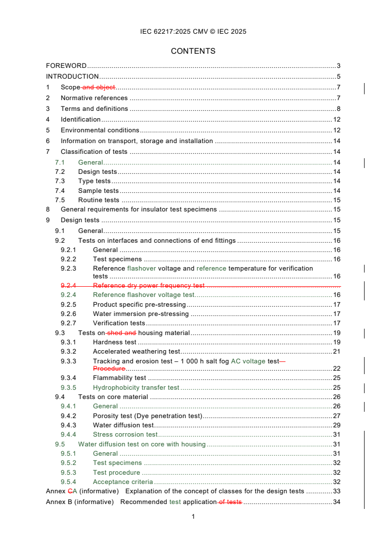
CONTENTS
FOREWORD . 3
INTRODUCTION . 5
1 Scope and object . 7
2 Normative references . 7
3 Terms and definitions . 8
4 Identification . 12
5 Environmental conditions . 12
6 Information on transport, storage and installation . 14
7 Classification of tests . 14
7.1 General . 14
7.2 Design tests . 14
7.3 Type tests . 14
7.4 Sample tests . 14
7.5 Routine tests . 15
8 General requirements for insulator test specimens . 15
9 Design tests . 15
9.1 General . 15
9.2 Tests on interfaces and connections of end fittings . 16
9.2.1 General . 16
9.2.2 Test specimens . 16
9.2.3 Reference flashover voltage and reference temperature for verification
tests . 16
9.2.4 Reference dry power frequency test .
9.2.4 Reference flashover voltage test. 16
9.2.5 Product specific pre-stressing . 17
9.2.6 Water immersion pre-stressing . 17
9.2.7 Verification tests . 17
9.3 Tests on shed and housing material . 19
9.3.1 Hardness test . 19
9.3.2 Accelerated weathering test . 21
9.3.3 Tracking and erosion test – 1 000 h salt fog AC voltage test –
Procedure . 22
9.3.4 Flammability test . 25
9.3.5 Hydrophobicity transfer test . 25
9.4 Tests on core material . 26
9.4.1 General . 26
9.4.2 Porosity test (Dye penetration test) . 27
9.4.3 Water diffusion test . 29
9.4.4 Stress corrosion test . 31
9.5 Water diffusion test on core with housing . 31
9.5.1 General . 31
9.5.2 Test specimens . 32
9.5.3 Test procedure . 32
9.5.4 Acceptance criteria . 32
Annex CA (informative) Explanation of the concept of classes for the design tests . 33
Annex B (informative) Recommended test application of tests . 34
Annex C (informative) Tests for AC or DC application . 36
Annex AD (informative) Difference between the tracking and erosion and accelerated
ageing test on polymeric insulators . 37
Annex E (informative) Consideration of electric field control . 38
Bibliography . 40
List of comments. 41
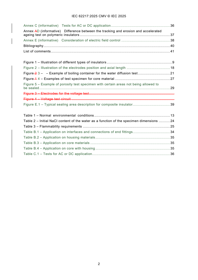
Figure 1 – Illustration of different types of insulators . 9
Figure 2 – Illustration of the electrodes position and axial length . 18
Figure 2 3 – – Example of boiling container for the water diffusion test . 21
Figure 1 4 – Examples of test specimen for core material . 27
Figure 5 – Example of porosity test specimen with certain areas not being allowed to
be sealed . 29
Figure 3 – Electrodes for the voltage test .
Figure 4 – Voltage test circuit .
Figure E.1 – Typical sealing area description for composite insulator . 39
Table 1 – Normal environmental conditions . 13
Table 2 – Initial NaCI content of the water as a function of the specimen dimensions . 24
Table 3 – Flammability requirements . 25
Table B.1 – Application on interfaces and connections of end fittings. 34
Table B.2 – Application on housing materials . 35
Table B.3 – Application on core materials . 35
Table B.4 – Application on core with housing . 35
Table C.1 – Tests for AC or DC application . 36
INTERNATIONAL ELECTROTECHNICAL COMMISSION
____________
Polymeric HV insulators for indoor and outdoor use -
General definitions, test methods and acceptance criteria
FOREWORD
1) The International Electrotechnical Commission (IEC) is a worldwide organization for standardization comprising
all national electrotechnical committees (IEC National Committees). The object of IEC is to promote international
co-operation on all questions concerning standardization in the electrical and electronic fields. To this end and
in addition to other activities, IEC publishes International Standards, Technical Specifications, Technical Reports,
Publicly Available Specifications (PAS) and Guides (hereafter referred to as “IEC Publication(s)”). Their
preparation is entrusted to technical committees; any IEC National Committee interested in the subject dealt with
may participate in this preparatory work. International, governmental and non-governmental organizations liaising
with the IEC also participate in this preparation. IEC collaborates closely with the International Organization for
Standardization (ISO) in accordance with conditions determined by agreement between the two organizations.
2) The formal decisions or agreements of IEC on technical matters express, as nearly as possible, an international
consensus of opinion on the relevant subjects since each technical committee has representation from all
interested IEC National Committees.
3) IEC Publications have the form of recommendations for international use and are accepted by IEC National
Committees in that sense. While all reasonable efforts are made to ensure that the technical content of IEC
Publications is accurate, IEC cannot be held responsible for the way in which they are used or for any
misinterpretation by any end user.
4) In order to promote international uniformity, IEC National Committees undertake to apply IEC Publications
transparently to the maximum extent possible in their national and regional publications. Any divergence between
any IEC Publication and the corresponding national or regional publication shall be clearly indicated in the latter.
5) IEC itself does not provide any attestation of conformity. Independent certification bodies provide conformity
assessment services and, in some areas, access to IEC marks of conformity. IEC is not responsible for any
services carried out by independent certification bodies.
6) All users should ensure that they have the latest edition of this publication.
7) No liability shall attach to IEC or its directors, employees, servants or agents including individual experts and
members of its technical committees and IEC National Committees for any personal injury, property damage or
other damage of any nature whatsoever, whether direct or indirect, or for costs (including legal fees) and
expenses arising out of the publication, use of, or reliance upon, this IEC Publication or any other IEC
Publications.
8) Attention is drawn to the Normative references cited in this publication. Use of the referenced publications is
indispensable for the correct application of this publication.
9) IEC draws attention to the possibility that the implementation of this document may involve the use of (a)
patent(s). IEC takes no position concerning the evidence, validity or applicability of any claimed patent rights in
respect thereof. As of the date of publication of this document, IEC had not received notice of (a) patent(s), which
may be required to implement this document. However, implementers are cautioned that this may not represent
the latest information, which may be obtained from the patent database available at https://patents.iec.ch. IEC
shall not be held responsible for identifying any or all such patent rights.
This commented version (CMV) of the official standard IEC 62217:2025 edition 3.0 allows the
user to identify the changes made to the previous IEC 62217:2012 edition 2.0. Furthermore,
comments from IEC TC 36 experts are provided to explain the reasons of the most relevant
changes, or to clarify any part of the content.
A vertical bar appears in the margin wherever a change has been made. Additions are in green
text, deletions are in strikethrough red text. Experts' comments are identified by a blue-
background number. Mouse over a number to display a pop-up note with the comment.
This publication contains the CMV and the official standard. The full list of comments is available
at the end of the CMV.
IEC 62217 has been prepared by IEC technical committee 36: Insulators. It is an International
Standard.
This third edition cancels and replaces the second edition published in 2012. This edition
constitutes a technical revision.
This edition includes the following significant technical changes with respect to the previous
edition:
a) The scope of the document is specified to comprise composite insulators with solid and
hollow core and resin insulators used for both AC and DC systems in indoor and outdoor
applications of HV overhead lines and substations; hybrid insulators (defined in
IEC TS 62896) with ceramic core and polymeric housing are also included, while coated
insulators (e.g. with Room Temperature Vulcanized (RTV) silicone rubber coatings) are not
considered in this document;
b) Steep-front impulse voltage test is modified to avoid unwanted flashovers between the leads
of the electrodes;
c) Differences between hydrophobicity transfer material (HTM) and non-HTM housing
materials are specified and relevant test methods and acceptance criteria for polymeric
insulators with HTM housing are introduced;
d) The previous water diffusion test on core materials with or without housing is split into two
tests. One is on core materials without housing, the other is on core materials with housing.
The acceptance criteria are modified;
e) Stress corrosion test for core materials is introduced;
f) Annex B summarizes the test application for evaluating the quality of interfaces and
connections of end fittings, housing materials and core materials;
g) Annex E is introduced to emphasize the need for control of electric fields of polymeric
insulators for AC. The control of electric fields of polymeric insulators for DC is still under
consideration.
The text of this International Standard is based on the following documents:
Draft Report on voting
36/612/FDIS 36/631/RVD
Full information on the voting for its approval can be found in the report on voting indicated in
the above table.
The language used for the development of this International Standard is English.
This document was drafted in accordance with ISO/IEC Directives, Part 2, and developed in
accordance with ISO/IEC Directives, Part 1 and ISO/IEC Directives, IEC Supplement, available
at www.iec.ch/members_experts/refdocs. The main document types developed by IEC are
described in greater detail at www.iec.ch/publications.
The committee has decided that the contents of this document will remain unchanged until the
stability date indicated on the IEC website under webstore.iec.ch in the data related to the
specific document. At this date, the document will be
• reconfirmed,
• withdrawn, or
• revised.
INTRODUCTION
Polymeric insulators consist either of one insulating material (resin insulators) or two or several
insulating materials (composite insulators). The insulating materials are generally cross-linked
organic materials synthesised from carbon or silicon chemistry and form the insulating body.
Insulating materials can be composed from organic materials containing various inorganic and
organic ingredients, such as fillers and extenders. End fittings are often used at the ends of the
insulating body to transmit mechanical loads. Despite these common features, the materials
used and the construction details employed by different manufacturers may be widely different
might differ significantly.
The tests given in this document are those which are, in general, common to a great majority
of insulator designs and materials, whatever their final application. Considering the increasing
applications of polymeric insulators, the scope of this document specifies technical
requirements for solid core, hollow core and resin insulators used in AC and DC systems, in
indoor and outdoor, in applications of HV overhead lines and substations to ensure proper
insulator performance under normal operating conditions. The technical requirements have
been regrouped in this document to avoid repetition of the relevant product standards and drift
between procedures as the various product standards are drafted or revised.
The majority of these tests have been grouped together as "Design tests", to be performed only
once for insulators of the same design. The design tests are intended to eliminate insulator
designs, materials or manufacturing technologies which are not suitable for high voltage (HV)
applications. The influence of time on the electrical properties of the complete polymeric
insulator and its components (core material, housing, interfaces etc.) has been considered in
specifying the design tests in order to ensure a satisfactory lifetime under normal operating and
environmental conditions. To ensure quality and reliable long-term performance of insulators,
the requirements on the modification of certain test procedures as well as the introduction of
new tests were identified.
Pollution tests, according to IEC 60507 or IEC TS 61245 [1] , are not included in this document,
the applicability of their methodology to composite insulators not having been proven and still
requiring study by CIGRE. The results of such pollution tests performed on insulators made of
polymeric materials do not correlate with experience obtained from service. Specific pollution
tests for polymeric insulators are still under consideration of IEC, indications for design
considering pollution are given in IEC TS 60815-1, IEC TS 60815-3 [2] and IEC TS 60815-4 [3].
The 1 000 hour salt-fog tracking and erosion test given in this second edition of IEC 62217 is
considered as a screening test intended to reject materials or designs which are inadequate.
This test is not intended to predict long term performance for insulator designs under cumulative
service stresses. For more information, see Annex C. The first edition of IEC 62217 (2005)
included two other alternative tracking and erosion tests (a 5 000 hour multi-stress test and a
tracking wheel test) which were based on tests developed by CIGRE and utilities. These tests
are no longer given as normative alternatives following the results of a study/questionnaire by
TC 36 on the relative merits of all three tracking and erosion tests. The 5 000 hour multi-stress
test and a tracking wheel test are described in IEC/TR 62730 (2012).
Composite insulators are used in both a.c. and d.c. applications. In spite of this fact a specific
tracking and erosion test procedure for d.c. applications as a design test has not yet been
defined and accepted. The 1 000 hour a.c. tracking and erosion test described in this standard
is used to establish a minimum requirement for the tracking resistance of the housing material.
Before the appropriate standard for DC applications will be issued, the majority of tests listed
in this document can also be applied to DC insulators. The 1 000 h AC salt fog tracking and
erosion test is considered as a design test in this document to reject materials in combination
with the design which are inadequate. For the time being, the 1 000 h AC salt fog tracking and
___________
Numbers in square brackets refer to the Bibliography.
erosion test is used to establish a minimum requirement for the tracking and erosion resistance,
for both AC and DC 1. For DC applications, a specific DC tracking and erosion test procedure
as a design test has not been developed. Further tracking and erosion test methods such as
the 5 000 hour and the tracking wheel test are described in IEC TR 62730 [4] and can be used
for research or other purposes. Tracking and erosion tests are not intended to evaluate long
term performance of insulators in harsh environments by the simulation of multiple
environmental factors. It is therefore necessary to carry out ageing tests for insulator designs
under cumulative service stresses. These aging tests do not form part of this present document.
For polymeric insulators with hydrophobicity transfer property, relevant test procedures are
introduced. In this document the hydrophobicity transfer test is intended to distinguish the HTM
from non-HTM rather than differentiate between different HTMs degrees.
The water diffusion test is divided into two tests. The first one is for the core (as earlier), the
second one is for the core with housing. The water diffusion test on core with housing addresses
the interface between the core and the housing. The acceptance criteria are modified and
harmonized for both tests.
Stress corrosion test for insulators mainly subjected to tensile loads is introduced to minimize
the risks of brittle fractures.
Annex B summarizes the test application for evaluating the quality of interfaces and
connections of end fittings, housing materials and core materials.
Annex E is introduced to emphasize the need for the control of electric field of polymeric
insulators under AC voltage.
IEC Guide 111 has been followed wherever possible during the preparation of this document.
1 Scope and object
This International Standard is applicable to polymeric insulators for AC systems with a nominal
voltage greater than 1 000 V (frequency less than 100 Hz) and DC systems with a nominal
voltage greater than 1 500 V whose insulating body consists of one or various organic materials.
Polymeric insulators covered by this standard include both solid core and hollow insulators.
They are intended for use on HV overhead lines and in indoor and outdoor equipment. Polymeric
insulators covered by this document are intended for use both on HV overhead lines and in
substations, in both indoor and outdoor applications 2. They include composite insulators with
solid and hollow core and resin insulators. Hybrid insulators with ceramic core and polymeric
housing are also included, while coated insulators (e.g. with RTV silicone rubber coatings) are
not included in this standard 3. Electrical tests described in this document are done under AC
voltage and are in general applicable to insulators to be used in DC systems too. Tests under
DC voltage are intended to reflect up-to-date knowledge and experience.
NOTE Only polymeric housing materials of hybrid insulators are specified in this document. Tests for core materials
and the interfaces between housing and core of hybrid insulators are not included. 4
The object of this document is
– to define the common terms used for polymeric insulators;
– to prescribe common test methods for design tests on polymeric insulators;
– to prescribe acceptance or failure criteria, if applicable;
These tests, criteria and recommendations are intended to ensure a satisfactory lifetime under
normal operating and environmental conditions (see Clause 5). This standard shall only be
applied in conjunction with the relevant product standard. This document includes design tests
intended to reject materials or designs which are inadequate under normal operating and
environmental conditions. This document defines test methods and acceptance criteria. The
applicable tests are given in the relevant product standard.
2 Normative references
The following documents are referred to in the text in such a way that some or all of their content
constitutes requirements of this document. For dated references, only the edition cited applies.
For undated references, the latest edition of the referenced document (including any
amendments) applies.
IEC 60050-471:2007, International Electrotechnical Vocabulary (IEV) - Part 471: Insulators
IEC 60060-1, High-voltage test techniques - Part 1: General definitions and test requirements
IEC 60068-2-11, Environmental testing – Part 2: Tests. Test KA: Salt mist
IEC 60507:2013+COR1:2018, Artificial pollution tests on high-voltage ceramic and glass
insulators to be used on a.c. systems
IEC 60695-11-10, Fire hazard testing - Part 11-10: Test flames - 50 W horizontal and vertical
flame test methods
IEC 60721-1, Classification of environmental conditions - Part 1: Environmental parameters and
their severities
IEC TS 60815-1, Selection and dimensioning of high-voltage insulators intended for use in
polluted conditions - Part 1: Definitions, information and general principles
IEC TR 62039:2021, Selection guidelines for polymeric materials for outdoor use under HV
stress
ISO 868, Plastics and ebonite - Determination of indentation hardness by means of a durometer
(Shore hardness)
ISO 4287, Geometrical product specifications (GPS) – Surface texture: Profile method – Terms,
definitions and surface texture parameters
ISO 4892-1, Plastics – Methods of exposure to laboratory light sources – Part 1: General
Guidance
ISO 4892-2, Plastics - Methods of exposure to laboratory light sources - Part 2; Xenon-arc
lamps
ISO 21920-2, Geometrical product specifications (GPS) Surface texture: Profile - Part 2: Terms,
definitions and surface texture parameters
3 Terms and definitions 5
For the purposes of this document, the terms and definitions given in IEC 60050-471:2007 and
the following apply.
ISO and IEC maintain terminology databases for use in standardization at the following
addresses:
• IEC Electropedia: available at https://www.electropedia.org/
• ISO Online browsing platform: available at https://www.iso.org/obp
3.1
high voltage
HV
voltage over 1 000 V AC or over 1 500 V DC or over 1 500 V peak value
3.2
polymeric insulator
insulator whose insulating body consists of at least one organic based material
Note 1 to entry: Polymeric insulators are also known as non-ceramic insulators.
Note 2 to entry: Coupling devices may be attached to the ends of the insulating body.
[SOURCE: IEC 60050-471:2007, 471-01-13]
3.3
resin insulator
polymeric insulator whose insulating body consists of a solid shank insulator trunk and sheds
protruding from the shank insulator trunk made from only one organic based housing material
(e.g. cycloaliphatic epoxy)
3.4
composite insulator
insulator made of at least two insulating parts, namely a core and a housing, equipped with
metal end fittings
Note 1 to entry: Composite insulators, for example, can consist either of individual sheds mounted on the core, with
or without an intermediate sheath, or alternatively, of a housing directly moulded or cast in one or several pieces on
to the core.
[SOURCE: IEC 60050-471:2007, 471-01-02]
3.5
hybrid insulator
insulator that consists of a ceramic core and a polymeric housing, equipped with one or more
metal fittings
Figure 1 – Illustration of different types of insulators
SEE: Figure 1.
Note 1 to entry: According to IEC TS 62896 [5].
Note 2 to entry: The mechanical functions are mainly characterised by the core, the external electrical functions
are mainly characterised by the polymeric housing. The housing may cover the core completely or partly. In the latter
case the exposed portions of the ceramic core are usually covered by glaze.
3.6
composite insulator with fibre reinforced plastic (FRP) solid core
composite insulators of which the core, covered by polymeric housing, is made of solid
insulating polymeric material reinforced by fibres such as glass fibres
3.7
composite hollow insulator
insulator consisting of at least two insulating parts, namely a tube-shaped core, and a housing
Note 1 to entry: The housing may consist either of individual sheds mounted on the tube, with or without an
intermediate sheath, or directly applied in one or several pieces onto the tube. A composite hollow insulator unit is
permanently equipped with fixing devices or end fittings.
3.8
core
central insulating part of an insulator which provides the mechanical characteristics
Note 1 to entry: The housing and sheds are not part of the core.
[SOURCE: IEC 60050-471:2007, 471-01-03]
3.9
insulator trunk
central insulating part of an insulator from which the sheds project
Note 1 to entry: Also known as shank on smaller insulators.
[SOURCE: IEC 60050-471:2007, 471-01-11]
3.10
housing
external insulating part of a composite insulator providing the necessary creepage distance and
protecting core from environment
Note 1 to entry: An intermediate sheath made of insulating material may be part of the housing.
[SOURCE: IEC 60050-471:2007, 471-01-09]
3.11
sheath
uniform and continuous tubular covering made of insulating material
[SOURCE: IEC 60050-151:2001, 151-12-41]
3.12
shed (of an insulator)
insulating part, projecting from the insulator trunk, intended to increase the creepage distance
Note 1 to entry: The shed can be with or without ribs.
[SOURCE: IEC 60050-471:2007, 471-01-15]
3.13
creepage distance
shortest distance or the sum of the shortest distances along the surface on an insulator between
two conductive parts which normally have the operating voltage between them
Note 1 to entry: The surface of cement or of any other non-insulating jointing material is not considered as forming
part of the creepage distance.
Note 2 to entry: If a high resistance coating is applied to parts of the insulating part of an insulator, such parts are
considered to be effective insulating surfaces and the distance over them is included in the creepage distance.
[SOURCE: IEC 60050-471:2007, 471-01-04, modified (removal of Note 2 to entry)]
3.14
arcing distance
shortest distance in air external to the insulator between the metallic parts which normally have
the operating voltage between them
[SOURCE: IEC 60050-471:2007, 471-01-01]
3.15
interfaces
surface between the different materials
Note 1 to entry: Various interfaces occur exist in most composite insulators, e.g.:
− between housing and fixing devices end fittings;
− between various parts of the housing; e.g. between separately manufactured sheds, or between sheath and
sheds;
− between core and housing.
− between sealant and core
− between sealant and end fittings
3.16
end fitting
fixing device
integral component or formed part of an insulator, intended to connect it to a supporting
structure, or to a conductor, or to an item of equipment, or to another insulator
Note 1 to entry: Where the end fitting is metallic, the term "metal fitting" is normally used.
[SOURCE: IEC 60050-471:2007, 471-01-06, modified by the addition of a synonym]
3.13
connection zone
zone where the mechanical load is transmitted between the insulating body and the fixing device
3.17
coupling
part of the fixing device end fitting which transmits load to the hardware external to the insulator
3.18
tracking
process which forms irreversible degradation by formation of conductive paths (tracks) starting
and developing on the surface of an insulating material.
progressive formation of conductive paths, which are produced on the surface or within a solid
insulating material, due to the combined effects of electric stress and electrolytic contamination
Note 1 to entry: Tracking paths are conductive even under dry conditions.
[SOURCE: IEC 60050-212:2010, 212-11-56, modified (addition of Note 1 to entry)]
3.19
erosion
irreversible and non-conducting degradation of the surface of the insulator that occurs by loss
of material. This can be uniform, localized or tree-shaped
loss of material by electrical discharge
Note 1 to entry: Light Surface traces, commonly tree-shaped, can occur on composite insulators as on ceramic and
glass insulators, after partial flashover exposure to surface discharges. These traces are not considered to be
objectionable as long as they are non-conductive. When they are conductive they are classified as tracking.
3.20
crack
any internal fracture or surface fissure of depth greater than 0,1 mm
3.21
puncture
permanent loss of dielectric strength due to a disruptive discharge passing through the solid
insulating material of an insulator
[SOURCE: IEC 60050-471:2007, 471-01-14, modified to define puncture as the result of a
discharge, rather than the discharge itself]
3.22
hydrophobicity
surface of a solid insulating material characterized by its capacity to repel water or aqueous
electrolyte solutions
Note 1 to entry: Hydrophobicity of a polymeric insulating material is, in general, a volume property by means of the
chemical composition of a material at its surface.
Note 2 to entry: Nonetheless, hydrophobicity is strongly affected by surface effects such as:
surface structure (i. e. roughness);
chemical interaction between water and the solid surface (adsorption, absorption, swelling of the solid material
in contact with water);
an accumulated pollution layer.
Note 3 to entry: Furthermore, the conditions during an evaluation of hydrophobicity (temperature, pressure,
humidity), and the method for cleaning or electrostatic charges can affect the measured degree of hydrophobicity.
[SOURCE: IEC TR 62039: 2021, 3.1, modified (deleting of "climatic" in Note 3 to entry)]
3.23
hydrophobicity transfer
phenomenon of a transfer of hydrophobicity from the bulk of the housing material to pollution
layer on its surface
3.24
hydrophobicity transfer material
HTM
polymeric material which exhibits hydrophobicity and the capability to transfer hydrophobicity
onto the layer of pollution, which is a combined dynamic behaviour of retention and transfer of
hydrophobicity specific to different insulator materials
[SOURCE: IEC TS 60815-4:2016 [3], 3.1.4, modified (addition of text from "which is …")]
4 Identification
The manufacturer's drawing shall show the relevant dimensions and information necessary for
identifying and testing the insulator in accordance with this document and the applicable IEC
product standard(s). The drawing shall also show applicable manufacturing tolerances.
Each insulator shall be marked with the name or trademark of the manufacturer and the year of
manufacture. In addition, each insulator shall be marked with the rated characteristics specified
in the relevant IEC product standards. These markings shall be legible, indelible and their
fixings (if any) weather- and corrosion-proof.
5 Environmental conditions
The normal environmental conditions to which insulators are submitted in service are defined
according to Table 1. Terms are defined as follows:
When special environmental conditions prevail at the location where insulators are to be put in
service, they shall be specified by the user by reference to IEC 60721-1.
Table 1 – Normal environmental conditions 6
Indoor insulation Outdoor insulation
Maximum ambient air Does not exceed 40 °C and its average value measured over a period of
a
24 h does not exceed 35 °C
temperature
b
−25 °C −40 °C
Minimum ambient air temperature
Negligible vibration due to causes external to the insulators or to earth
Vibration
c
tremors .
bd 2
To be neglected Not applicable
Solar radiation Up to a level of 1 000 1 120 W/m
Pollution of the ambient air Site No significant pollution by dust, Pollution by dust, smoke, corrosive
e
smoke, corrosive and/or gases, vapors or salt may occur
pollution severity
flammable gases, vapors, or salt. occurs. Pollution does not exceed
"heavy" SPS class as defined in
IEC TS 60815-1.
f
The average value of the relative Rain, snow, abnormal humidity,
Humidity
humidity, measured over a period condensation, ice and hoar frost
of 24 h, does not exceed 95 % occur.
and measured over a period of
one month, does not exceed
95 %. For these conditions,
condensation may occasionally
occur. No rain, snow, abnormal
humidity, condensation, ice and
hoar frost
a
If exceeded, follow the recommendations of IEC TR 62039 for the core and adhesive materials (like glue) in
"glass transition temperature" section.
b
Details of solar radiation are given in IEC 60721-1.
b
In general, temperatures below −40 °C are non-critical for service. However, for handling and installation the
crystallization temperature of the polymeric housing is to be considered. For line installations during wintertime
with temperatures below −20 °C, special steel grades with low ductile transition temperature can be specified.
c
Vibration due to external causes can be dealt with in accordance with IEC 60721-1.
d 2
For outdoor application, the influence of deviation from the assumed level of 1 120 W/m depends on the
insulator material. If service conditions of polymeric insulators deviate significantly from the parameters in
Table 1, the insulator is to be designed/evaluated taking into account relevant service experience. In the
absence of significant service experience, special tests simulating the solar radiation condition of the
installation area have to be carried out.
e
In general, pollution is not an issue for indoor insulators. In particular cases, such as DC indoor conditions,
the insulators can accumulate some contamination due to DC electric field. However, the pollution flashover
phenomena cannot develop when the humidity is controlled. For outdoor conditions the requirements of this
document are specified for stresses arising in relatively harsh but not extreme environments (see e.g. for
hydrophobicity verification and tracking and erosion tests for which criteria are provided in IEC TR 62039).
f
Insulator for indoor applications can also be used in presence of limited deviations from the above conditions
if sufficient proven field experience is available and condensation occurs only occasionally. To limit
condensation-related phenomena, the average value of the relative humidity condition, measured over a period
of 24 h, shall not exceed 95 % and when measured over a period of one month, shall not exceed 90 %.
Exceeding these values is considered as abnormal humidity condition.
• Indoor environment: installation within a building or other construction where the insulators
are protected against wind, rain, snow, periodical fast-built pollution deposits, abnormal
condensation, ice and hoar frost.
• Outdoor environment: installation in open air outside any building or shelter, where the
insulators are capable to withstand wind, rain, snow, periodical fast-built pollution deposits,
high condensation, ice and hoar frost.
,
If service conditions of polymeric insulators deviate significantly from the parameters in Table 1
the insulator is to be designed or evaluated according to agreement between the customer and
manufacturer. Alternatively, if positive service experience is available for a specific environment
and specific insulator design (including material and profile), the insulator can be used for this
specific environment, deviating from normal environmental conditions. 7
6 Information on transport, storage and installation
Manufacturers of insulators shall provide appropriate instructions and information covering
general conditions during transport, storage and installation of the insulators. These instructions
can include recommendations for cleaning or maintenance and correct positioning and
installation of the corona rings.
7 Classification of tests
7.1 General
The tests are divided into four groups as follows:
7.2 Design tests
The design tests are intended to verify the suitability of the design, materials and method of
manufacturing (technology).
A polymeric insulator design is generally defined by:
• materials of the core, housing and manufacturing method;
• material of the end fittings, their design, and method of attachment;
• layer thickness of the housing over the core (including a sheath where used).
Additional parameters defining design may be given in the relevant product standard.
When changes in the design of a polymeric insulator occur, re-qualification shall be carried out
according to the prescriptions of the relevant product standard. Typically, only part of the tests
is repeated. A survey of the tests is given in Annex C. Explanation of the concept of classes for
the design tests is provided in Annex A.
When a polymeric insulator is submitted to the design tests, it becomes a parent insulator for a
design class and the results shall
...
IEC 62217 ®
Edition 3.0 2025-10
NORME
INTERNATIONALE
Isolateurs polymériques à haute tension pour usage intérieur et extérieur -
Définitions générales, méthodes d'essai et critères d'acceptation
ICS 29.080.10 ISBN 978-2-8327-0690-9
Droits de reproduction réservés. Sauf indication contraire, aucune partie de cette publication ne peut être reproduite ni
utilisée sous quelque forme que ce soit et par aucun procédé, électronique ou mécanique, y compris la photocopie et
les microfilms, sans l'accord écrit de l'IEC ou du Comité national de l'IEC du pays du demandeur. Si vous avez des
questions sur le copyright de l'IEC ou si vous désirez obtenir des droits supplémentaires sur cette publication, utilisez
les coordonnées ci-après ou contactez le Comité national de l'IEC de votre pays de résidence.
IEC Secretariat Tel.: +41 22 919 02 11
3, rue de Varembé info@iec.ch
CH-1211 Geneva 20 www.iec.ch
Switzerland
A propos de l'IEC
La Commission Electrotechnique Internationale (IEC) est la première organisation mondiale qui élabore et publie des
Normes internationales pour tout ce qui a trait à l'électricité, à l'électronique et aux technologies apparentées.
A propos des publications IEC
Le contenu technique des publications IEC est constamment revu. Veuillez vous assurer que vous possédez l’édition la
plus récente, un corrigendum ou amendement peut avoir été publié.
Recherche de publications IEC - IEC Products & Services Portal - products.iec.ch
webstore.iec.ch/advsearchform Découvrez notre puissant moteur de recherche et consultez
La recherche avancée permet de trouver des publications gratuitement tous les aperçus des publications, symboles
IEC en utilisant différents critères (numéro de référence, graphiques et le glossaire. Avec un abonnement, vous aurez
texte, comité d’études, …). Elle donne aussi des toujours accès à un contenu à jour adapté à vos besoins.
informations sur les projets et les publications remplacées
ou retirées. Electropedia - www.electropedia.org
Le premier dictionnaire d'électrotechnologie en ligne au
IEC Just Published - webstore.iec.ch/justpublished monde, avec plus de 22 500 articles terminologiques en
Restez informé sur les nouvelles publications IEC. Just anglais et en français, ainsi que les termes équivalents
dans 25 langues additionnelles. Egalement appelé
Published détaille les nouvelles publications parues.
Disponible en ligne et une fois par mois par email. Vocabulaire Electrotechnique International (IEV) en ligne.
Service Clients - webstore.iec.ch/csc
Si vous désirez nous donner des commentaires sur cette
publication ou si vous avez des questions contactez-
nous: sales@iec.ch.
SOMMAIRE
AVANT-PROPOS . 3
INTRODUCTION . 5
1 Domaine d'application . 7
2 Références normatives . 7
3 Termes et définitions . 8
4 Identification . 12
5 Conditions d'environnement . 12
6 Informations relatives au transport, au stockage et à l'installation . 14
7 Classification des essais . 14
7.1 Généralités . 14
7.2 Essais de conception . 14
7.3 Essais de type . 15
7.4 Essais sur prélèvements . 15
7.5 Essais individuels de série . 15
8 Exigences générales pour les éprouvettes d'isolateurs . 15
9 Essais de conception . 16
9.1 Généralités . 16
9.2 Essais sur les interfaces et les connexions des armatures d'extrémité . 16
9.2.1 Généralités . 16
9.2.2 Éprouvettes . 16
9.2.3 Tension de contournement de référence et température de référence
pour les essais de vérification . 16
9.2.4 Essai de tension de contournement de référence . 17
9.2.5 Précontrainte spécifique au produit . 17
9.2.6 Précontrainte par immersion dans l'eau . 17
9.2.7 Essais de vérification . 17
9.3 Essais sur le matériau du revêtement . 19
9.3.1 Essai de dureté . 19
9.3.2 Essai climatique accéléré . 20
9.3.3 Essai de cheminement et d'érosion – essai au brouillard salin de
1 000 h sous tension alternative . 21
9.3.4 Essai d'inflammabilité . 24
9.3.5 Essai de transfert d'hydrophobie . 24
9.4 Essais sur le matériau du noyau . 26
9.4.1 Généralités . 26
9.4.2 Essai de porosité (essai de pénétration de colorant) . 26
9.4.3 Essai de pénétration d'eau . 27
9.4.4 Essai de corrosion sous contrainte . 28
9.5 Essai de pénétration d'eau sur le noyau avec le revêtement . 28
9.5.1 Généralités . 28
9.5.2 Éprouvettes . 28
9.5.3 Procédure d'essai . 29
9.5.4 Critères d'acceptation . 29
Annexe A (informative) Explication du concept de classes pour les essais de
conception . 30
Annexe B (informative) Application d'essai recommandée . 31
Annexe C (informative) Essais pour les applications en courant alternatif ou en
courant continu . 33
Annexe D (informative) Différence entre l'essai de cheminement et d'érosion et
l'essai de vieillissement accéléré sur les isolateurs polymériques . 34
Annexe E (informative) Prise en compte de la maîtrise des champs électriques . 35
Bibliographie . 37
Figure 1 – Différents types d'isolateurs . 9
Figure 2 – Position des électrodes et longueur axiale . 18
Figure 3 – Exemple de cuve à ébullition pour l'essai de pénétration d'eau . 20
Figure 4 – Exemples d'éprouvettes pour le matériau de noyau . 26
Figure 5 – Exemple d'éprouvette de porosité dont certaines zones ne peuvent pas être
scellées . 27
Figure E.1 – Description de la zone d'étanchéité type pou un isolateur composite . 36
Tableau 1 – Conditions normales d'environnement . 13
Tableau 2 – Teneur en NaCl initiale de l'eau en fonction des dimensions des
spécimens . 23
Tableau 3 – Exigences d'inflammabilité . 24
Tableau B.1 – Application pour les interfaces et les connexions des armatures
d'extrémité . 31
Tableau B.2 – Application pour les matériaux de revêtement . 31
Tableau B.3 – Application pour les matériaux de noyau . 31
Tableau B.4 – Application pour le noyau avec le revêtement . 32
Tableau C.1 – Essais pour les applications en courant alternatif ou en courant continu . 33
COMMISSION ÉLECTROTECHNIQUE INTERNATIONALE
____________
Isolateurs polymériques à haute tension pour usage intérieur et extérieur
- Définitions générales, méthodes d'essai et critères d'acceptation
AVANT-PROPOS
1) La Commission Électrotechnique Internationale (IEC) est une organisation mondiale de normalisation composée
de l'ensemble des comités électrotechniques nationaux (Comités nationaux de l'IEC). L'IEC a pour objet
de favoriser la coopération internationale pour toutes les questions de normalisation dans les domaines
de l'électricité et de l'électronique. À cet effet, l'IEC – entre autres activités – publie des Normes internationales,
des Spécifications techniques, des Rapports techniques, des Spécifications accessibles au public (PAS) et
des Guides (ci-après dénommés "Publication(s) de l'IEC"). Leur élaboration est confiée à des comités d'études,
aux travaux desquels tout Comité national intéressé par le sujet traité peut participer. Les organisations
internationales, gouvernementales et non gouvernementales, en liaison avec l'IEC, participent également
aux travaux. L'IEC collabore étroitement avec l'Organisation Internationale de Normalisation (ISO), selon
des conditions fixées par accord entre les deux organisations.
2) Les décisions ou accords officiels de l'IEC concernant les questions techniques représentent, dans la mesure
du possible, un accord international sur les sujets étudiés, étant donné que les Comités nationaux de l'IEC
intéressés sont représentés dans chaque comité d'études.
3) Les Publications de l'IEC se présentent sous la forme de recommandations internationales et sont agréées
comme telles par les Comités nationaux de l'IEC. Tous les efforts raisonnables sont entrepris afin que l'IEC
s'assure de l'exactitude du contenu technique de ses publications; l'IEC ne peut pas être tenue responsable
de l'éventuelle mauvaise utilisation ou interprétation qui en est faite par un quelconque utilisateur final.
4) Dans le but d'encourager l'uniformité internationale, les Comités nationaux de l'IEC s'engagent, dans toute
la mesure possible, à appliquer de façon transparente les Publications de l'IEC dans leurs publications nationales
et régionales. Toutes divergences entre toutes Publications de l'IEC et toutes publications nationales ou
régionales correspondantes doivent être indiquées en termes clairs dans ces dernières.
5) L'IEC elle-même ne fournit aucune attestation de conformité. Des organismes de certification indépendants
fournissent des services d'évaluation de conformité et, dans certains secteurs, accèdent aux marques
de conformité de l'IEC. L'IEC n'est responsable d'aucun des services effectués par les organismes de certification
indépendants.
6) Tous les utilisateurs doivent s'assurer qu'ils sont en possession de la dernière édition de cette publication.
7) Aucune responsabilité ne doit être imputée à l'IEC, à ses administrateurs, employés, auxiliaires ou mandataires,
y compris ses experts particuliers et les membres de ses comités d'études et des Comités nationaux de l'IEC,
pour tout préjudice causé en cas de dommages corporels et matériels, ou de tout autre dommage de quelque
nature que ce soit, directe ou indirecte, ou pour supporter les coûts (y compris les frais de justice) et les dépenses
découlant de la publication ou de l'utilisation de cette Publication de l'IEC ou de toute autre Publication de l'IEC,
ou au crédit qui lui est accordé.
8) L'attention est attirée sur les références normatives citées dans cette publication. L'utilisation de publications
référencées est obligatoire pour une application correcte de la présente publication.
9) L'IEC attire l'attention sur le fait que la mise en application du présent document peut entraîner l'utilisation d'un ou
de plusieurs brevets. L'IEC ne prend pas position quant à la preuve, à la validité et à l'applicabilité de tout droit
de brevet revendiqué à cet égard. À la date de publication du présent document, l'IEC n'avait pas reçu notification
qu'un ou plusieurs brevets pouvaient être nécessaires à sa mise en application. Toutefois, il y a lieu d'avertir
les responsables de la mise en application du présent document que des informations plus récentes
sont susceptibles de figurer dans la base de données de brevets, disponible à l'adresse https://patents.iec.ch.
L'IEC ne saurait être tenue pour responsable de ne pas avoir identifié de tels droits de brevets.
L'IEC 62217 a été établie par le comité d'études 36 de l'IEC: Isolateurs. Il s'agit d'une Norme
internationale.
Cette troisième édition annule et remplace la deuxième édition parue en 2012. Cette édition
constitue une révision technique.
Cette édition inclut les modifications techniques majeures suivantes par rapport à l'édition
précédente:
a) le domaine d'application du document couvre les isolateurs composites à noyau plein ou
creux, ainsi que les isolateurs en résine utilisés avec des systèmes à courant alternatif et
à courant continu, en intérieur et en extérieur, sur les lignes aériennes HT et
dans les postes; les isolateurs hybrides (définis dans l'IEC TS 62896) constitués d'un noyau
en céramique et d'un revêtement en polymère sont également inclus, tandis que
les isolateurs revêtus (avec des revêtements en caoutchouc silicone vulcanisé
à température ambiante (RTV), par exemple) ne sont pas couverts par le présent document;
b) l'essai sous onde de choc à front raide a été modifié pour éviter des contournements
indésirables entre les conducteurs des électrodes;
c) les différences entre le matériau de transfert d'hydrophobie (HTM - Hydrophobicity Transfer
Material) et les matériaux de revêtement non HTM ont été spécifiées, et les méthodes
d'essai et les critères d'acceptation pertinents pour les isolateurs polymériques
avec revêtement HTM ont été ajoutés;
d) l'essai précédent de pénétration d'eau sur les matériaux de noyau avec ou
sans le revêtement a été divisé en deux essais. L'un porte sur les matériaux de noyau
sans le revêtement, l'autre sur les matériaux de noyau avec le revêtement. Les critères
d'acceptation ont été modifiés;
e) l'essai de corrosion sous contrainte pour les matériaux de noyau a été ajouté;
f) l'Annexe B récapitule l'application de l'essai pour évaluer la qualité des interfaces et
connexions des armatures d'extrémité, des matériaux de revêtement et des matériaux
de noyau;
g) l'Annexe E a été ajoutée pour souligner la nécessité de maîtriser les champs électriques
dans les isolateurs polymériques pour systèmes à courant alternatif. La maîtrise
des champs électriques dans les isolateurs polymériques à courant continu est encore
à l'étude.
Le texte de cette Norme internationale est issu des documents suivants:
Projet Rapport de vote
36/612/FDIS 36/631/RVD
Le rapport de vote indiqué dans le tableau ci-dessus donne toute information sur le vote ayant
abouti à son approbation.
La langue employée pour l'élaboration de cette Norme internationale est l'anglais.
Ce document a été rédigé selon les Directives ISO/IEC, Partie 2, il a été développé
selon les Directives ISO/IEC, Partie 1 et les Directives ISO/IEC, Supplément IEC, disponibles
sous www.iec.ch/members_experts/refdocs. Les principaux types de documents développés
par l'IEC sont décrits plus en détail sous www.iec.ch/standardsdev/publications.
Le comité a décidé que le contenu de ce document ne sera pas modifié avant la date de stabilité
indiquée sur le site web de l'IEC sous webstore.iec.ch dans les données relatives au document
recherché. À cette date, le document sera
• reconduit,
• supprimé, ou
• révisé.
INTRODUCTION
Les isolateurs polymériques sont constitués soit d'un seul matériau isolant (isolateurs en résine),
soit d'au moins deux matériaux isolants (isolateurs composites). Les matériaux isolants
sont généralement des matériaux organiques réticulés provenant de la synthèse de carbone ou
de silicone, et constituent le corps isolant. Les matériaux isolants peuvent être composés
de matériaux organiques contenant différents ingrédients inorganiques et organiques,
comme les charges et les adjuvants. Des armatures d'extrémité sont souvent utilisées
aux extrémités du corps isolant afin de transmettre les charges mécaniques.
Malgré ces caractéristiques communes, les matériaux et les détails de construction utilisés
par les fabricants peuvent différer de manière significative.
Le présent document spécifie les essais qui sont généralement communs à la majorité
des conceptions et des matériaux d'isolateurs, quelle que soit leur application finale. Compte
tenu des applications croissantes des isolateurs polymériques, le domaine d'application
du présent document spécifie les exigences techniques pour les isolateurs à noyau plein,
les isolateurs à noyau creux et les isolateurs en résine utilisés avec des systèmes à courant
alternatif et à courant continu, en intérieur et en extérieur, sur les lignes aériennes HT et
dans les postes, afin d'assurer la qualité et la fiabilité des performances des isolateurs
dans des conditions normales d'exploitation. Les exigences techniques ont été regroupées
dans le présent document afin d'éviter les répétitions dans les normes de produits pertinentes
et des décalages entre les procédures lorsque les différentes normes de produits sont rédigées
ou révisées.
La majorité de ces essais ont été regroupés dans la classe des "essais de conception" et
ne doivent être effectués qu'une seule fois sur des isolateurs présentant la même conception.
Les essais de conception sont destinés à éliminer les conceptions, les matériaux ou
les technologies de fabrication d'isolateurs qui ne conviennent pas aux applications
à haute tension (HT). L'influence du temps sur les propriétés électriques des isolateurs
polymériques complets et de leurs composants (noyau, revêtement, interfaces, etc.) a été prise
en compte lors de la spécification des essais de conception, afin de procurer une durée de vie
satisfaisante des isolateurs dans les conditions normales d'exploitation et d'environnement.
Pour assurer la qualité et la fiabilité des performances à long terme des isolateurs,
les exigences relatives à la modification de certaines procédures d'essai et à l'introduction
de nouveaux essais ont été identifiées.
Les essais sous pollution, conformément à l'IEC 60507 ou à l'IEC TS 61245 [1] , ne sont pas
inclus dans le présent document. Des essais sous pollution spécifiques pour les isolateurs
polymériques sont à l'étude au sein de l'IEC. Des indications de conception prenant en compte
la pollution sont fournies dans l'IEC TS 60815-1, l'IEC TS 60815-3 [2] et l'IEC TS 60815-4 [3].
___________
Les chiffres entre crochets renvoient à la Bibliographie.
En attendant la publication de la norme pertinente pour les applications en courant continu,
la majorité des essais définis dans le présent document peuvent également s'appliquer
aux isolateurs à courant continu. L'essai de cheminement et d'érosion en courant alternatif
au brouillard salin de 1 000 h est considéré comme un essai de conception dans le présent
document et est destiné à rejeter les matériaux associés à la conception qui ne sont pas
appropriés. Pour le moment, l'essai de cheminement et d'érosion en courant alternatif
au brouillard salin de 1 000 h est utilisé afin de définir une exigence minimale pour la résistance
au cheminement et à l'érosion, tant en courant alternatif qu'en courant continu.
Pour les applications en courant continu, il n'existe pas de procédure d'essai de cheminement
et d'érosion en courant continu spécifique dans le cadre d'un essai de conception.
D'autres méthodes d'essai de cheminement et d'érosion, comme l'essai de 5 000 h et l'essai
de cheminement à la roue, sont décrites dans l'IEC TR 62730 [4] et peuvent être utilisées
à des fins de recherche ou autres. Les essais de cheminement et d'érosion ne sont pas destinés
à évaluer les performances à long terme des isolateurs dans des environnements difficiles
par la simulation de plusieurs facteurs d'environnement. Il est donc nécessaire d'effectuer
des essais de vieillissement pour les conceptions d'isolateurs soumis à des contraintes
de service cumulatives. Ces essais de vieillissement ne font pas partie du présent document.
Pour les isolateurs polymériques présentant des propriétés de transfert d'hydrophobie,
des procédures d'essai pertinentes ont été ajoutées. Dans le présent document, l'essai
de transfert d'hydrophobie s'applique à distinguer les matériaux dits HTM et les matériaux
non HTM, plutôt qu'à différencier les différents degrés de revêtement HTM.
L'essai de pénétration d'eau est divisé en deux essais. Le premier essai concerne le noyau seul
(comme par le passé), tandis que le second essai concerne le noyau avec le revêtement.
L'essai de pénétration d'eau sur le noyau avec le revêtement porte sur l'interface entre le noyau
et le revêtement. Les critères d'acceptation ont été modifiés et harmonisés pour les deux essais.
L'essai de corrosion sous contrainte pour les isolateurs essentiellement soumis à des charges
de traction a été ajouté afin de réduire le plus possible les risques de fractures fragiles.
L'Annexe B récapitule l'application de l'essai pour évaluer la qualité des interfaces et
connexions des armatures d'extrémité, des matériaux de revêtement et des matériaux de noyau.
L'Annexe E a été ajoutée pour souligner la nécessité de maîtriser les champs électriques
dans les isolateurs polymériques fonctionnant sous tension alternative.
Le Guide 111 de l'IEC a été suivi autant que possible pour l'élaboration du présent document.
1 Domaine d'application
La présente Norme internationale s'applique aux isolateurs polymériques pour systèmes
à courant alternatif de tension nominale supérieure à 1 000 V (fréquence inférieure à 100 Hz)
et pour systèmes à courant continu de tension nominale supérieure à 1 500 V, dont le corps
isolant est constitué d'un ou de plusieurs matériaux organiques. Les isolateurs polymériques
couverts par le présent document sont destinés à être utilisés sur les lignes aériennes HT et
dans les postes, en intérieur et en extérieur. Il s'agit d'isolateurs composites à noyau plein et
à noyau creux, ainsi que d'isolateurs en résine. Les isolateurs hybrides constitués d'un noyau
en céramique et d'un revêtement en polymère sont également inclus, tandis que les isolateurs
revêtus (avec des revêtements en caoutchouc silicone vulcanisé à température ambiante (RTV),
par exemple) ne sont pas couverts par la présente norme. Les essais électriques décrits
dans le présent document sont effectués sous une tension alternative et s'appliquent
généralement aux isolateurs destinés à être utilisés dans des systèmes à courant continu
également. Les essais sous tension continue sont prévus pour refléter l'état actuel
des connaissances et de l'expérience.
NOTE Seuls les matériaux de revêtement en polymère des isolateurs hybrides sont spécifiés dans le présent
document. Les essais pour les matériaux de noyau et les interfaces entre le revêtement et le noyau des isolateurs
hybrides ne sont pas inclus.
L'objet du présent document est
– De définir les termes couramment utilisés pour les isolateurs polymériques.
– De spécifier des méthodes d'essai communes pour les essais de conception
sur les isolateurs polymériques.
– De spécifier des critères d'acceptation ou de défaillance, le cas échéant.
Ces essais, critères et recommandations sont destinés à procurer une durée de vie
satisfaisante des isolateurs dans les conditions normales d'exploitation et d'environnement
(voir l'Article 5). Le présent document comprend des essais de conception destinés à rejeter
les matériaux ou les conceptions qui ne conviennent pas dans des conditions normales
d'exploitation et d'environnement. Le présent document définit les méthodes d'essai et
les critères d'acceptation. Les essais applicables sont définis dans la norme de produit
pertinente.
2 Références normatives
Les documents suivants sont cités dans le texte de sorte qu'ils constituent, pour tout ou partie
de leur contenu, des exigences du présent document. Pour les références datées, seule
l'édition citée s'applique. Pour les références non datées, la dernière édition du document
de référence s'applique (y compris les éventuels amendements).
IEC 60050-471:2007, Vocabulaire électrotechnique international - Partie 471: Isolateurs
IEC 60060-1, Techniques d'essai à haute tension - Partie 1: Définitions générales et exigences
d'essai
IEC 60507:2013+COR1:2018, Essais sous pollution artificielle des isolateurs haute tension
en céramique et en verre destinés aux réseaux à courant alternatif
IEC 60695-11-10, Essais relatifs aux risques du feu - Partie 11-10: Flammes d'essai - Méthodes
d'essai horizontal et vertical à la flamme de 50 W
IEC 60721-1, Classification des conditions d'environnement - Partie 1: Agents d'environnement
et leurs sévérités
IEC TS 60815-1, Sélection et dimensionnement des isolateurs haute tension utilisés
dans des conditions de pollution - Partie 1: Définitions, informations et principes généraux
IEC TR 62039:2021, Selection guidelines for polymeric materials for outdoor use under HV
stress (disponible en anglais seulement)
ISO 868, Plastiques et ébonite - Détermination de la dureté par pénétration au moyen
d'un duromètre (dureté Shore)
ISO 4892-2, Plastiques - Méthodes d'exposition à des sources lumineuses en laboratoire -
Partie 2: Lampes à arc au xénon
ISO 21920-2, Spécification géométrique des produits (GPS) - État de surface: Méthode du profil
- Partie 2: Termes, définitions et paramètres d'état de surface
3 Termes et définitions
Pour les besoins du présent document, les termes et définitions de l'IEC 60050-471:2007
ainsi que les suivants s'appliquent.
L'ISO et l'IEC tiennent à jour des bases de données terminologiques destinées à être utilisées
en normalisation, consultables aux adresses suivantes:
• IEC Electropedia: disponible à l'adresse https://www.electropedia.org/
• ISO Online browsing platform: disponible à l'adresse https://www.iso.org/obp
3.1
haute tension
HT
tension supérieure à 1 000 V en courant alternatif ou à 1 500 V en courant continu ou à 1 500 V
en valeur de crête
3.2
isolateur polymérique
isolateur dont le corps isolant se compose d'au moins un matériau organique
Note 1 à l'article: Cette note ne s'applique qu'au texte anglais.
Note 2 à l'article: Des dispositifs de couplage peuvent être fixés aux extrémités du corps isolant.
[SOURCE: IEC 60050-471:2007, 471-01-13]
3.3
isolateur en résine
isolateur polymérique dont le corps isolant se compose d'un fût plein et d'ilettes dépassant
du fût, réalisées à partir d'un seul matériau de revêtement organique
(par exemple, époxy cycloaliphatique)
3.4
isolateur composite
isolateur constitué d'au moins deux parties isolantes, un noyau et un revêtement, et équipé
d'armatures d'extrémité
Note 1 à l'article: Les isolateurs composites, par exemple, peuvent être constitués soit d'ailettes individuelles
montées sur le noyau, avec ou sans gaine intermédiaire, ou alternativement, d'un revêtement moulé ou coulé
directement sur le noyau en une ou plusieurs parties.
[SOURCE: IEC 60050-471:2007, 471-01-02]
3.5
isolateur hybride
isolateur constitué d'un noyau en céramique et d'un revêtement en polymère, et équipé d'une ou
de plusieurs armatures métalliques
Figure 1 – Différents types d'isolateurs
VOIR: Figure 1.
Note 1 à l'article: Conformément à l'IEC TS 62896 [5].
Note 2 à l'article: Les fonctions mécaniques sont principalement caractérisées par le noyau, tandis
que les fonctions électriques externes sont principalement caractérisées par le revêtement en polymère.
Le revêtement peut recouvrir le noyau entièrement ou partiellement. En cas de revêtement partiel, les parties
exposées du noyau en céramique sont généralement recouvertes d'émail.
3.6
isolateur composite à noyau plein renforcé par des fibres (FRP)
isolateur composite dont le noyau, recouvert d'un revêtement en polymère, est constitué
d'un matériau polymère isolant solide renforcé par des fibres telles que des fibres de verre
Note 1 à l'article: L'abréviation "FRP" est dérivée du terme anglais développé correspondant "fibre reinforced
plastic".
3.7
isolateur composite creux
isolateur constitué d'au moins deux parties isolantes, à savoir un noyau tubulaire et
un revêtement
Note 1 à l'article: Le revêtement peut soit être constitué d'ailettes individuelles montées sur le tube, avec ou
sans gaine intermédiaire, soit être appliqué directement sur le tube en une ou plusieurs parties. Un isolateur
composite creux est équipé en permanence de dispositifs de fixation ou d'armatures d'extrémité.
3.8
noyau
partie isolante interne d'un isolateur qui assure les caractéristiques mécaniques
Note 1 à l'article: Le revêtement et les ailettes ne font pas partie du noyau.
[SOURCE: IEC 60050-471:2007, 471-01-03]
3.9
fût d'un isolateur
partie isolante centrale d'un isolateur situé entre les ailettes
Note 1 à l'article: Cette note ne s'applique qu'au texte anglais.
[SOURCE: IEC 60050-471:2007, 471-01-11]
3.10
revêtement
partie isolante externe d'un isolateur composite, qui assure la ligne de fuite nécessaire et
protège le noyau de l'environnement
[SOURCE: IEC 60050-471:2007, 471-01-09]
3.11
gaine
revêtement tubulaire continu constitué de matériau isolant
[SOURCE: IEC 60050-151:2001, 151-12-41]
3.12
ailette (d'un isolateur)
partie isolante en saillie sur le fût d'un isolateur, destinée à augmenter la ligne de fuite
Note 1 à l'article: Une ailette peut être avec ou sans ondulations.
[SOURCE: IEC 60050-471:2007, 471-01-15]
3.13
ligne de fuite
distance la plus courte ou somme des distances les plus courtes le long de la surface
d'un isolateur entre deux parties conductrices qui supportent normalement la tension de service
entre elles
Note 1 à l'article: La surface du ciment ou de toute autre matière de scellement non isolante n'est pas considérée
comme faisant partie de la ligne de fuite.
[SOURCE: IEC 60050-471:2007, 471-01-04, modifié (suppression de la Note 2 à l'article)]
3.14
distance d'arc
plus courte distance dans l'air à l'extérieur de l'isolateur entre les parties métalliques sur
lesquelles on applique normalement la tension de service
[SOURCE: IEC 60050-471:2007, 471-01-01]
3.15
interfaces
surfaces de contact entre les différents matériaux
Note 1 à l'article: Les isolateurs composites comportent plusieurs interfaces, par exemple:
− entre le revêtement et les armatures d'extrémité;
− entre les différentes parties du revêtement, par exemple entre les ailettes fabriquées séparément ou entre
les ailettes et la gaine;
− entre le noyau et le revêtement;
− entre le produit d'étanchéité et le noyau;
− entre le produit d'étanchéité et les armatures d'extrémité.
3.16
armature de fixation,
armature d'extrémité
dispositif, faisant partie d'un isolateur, qui sert à fixer celui-ci à une structure de support,
à un conducteur, à une partie d'un équipement ou à un autre isolateur
Note 1 à l'article: Lorsque le dispositif de fixation est métallique, l'appellation "armature métallique"
est normalement utilisée.
[SOURCE: IEC 60050-471:2007, 471-01-06, modifié par l'ajout d'un synonyme]
3.17
couplage
partie de l'armature d'extrémité qui transmet la charge au matériel externe à l'isolateur
3.18
cheminement
formation progressive de chemins conducteurs à la surface ou dans un isolant solide,
sous l'effet combiné des contraintes électriques et de la contamination électrolytique
de cette surface
Note 1 à l'article: Les chemins sont conducteurs même dans des conditions sèches.
[SOURCE: IEC 60050-212:2010, 212-11-56, modifié (ajout de la Note 1 à l'article)]
3.19
érosion
perte de matière par décharge électrique
Note 1 à l'article: Après des décharges en surface, des traces superficielles, généralement arborescentes,
peuvent apparaître sur les isolateurs composites et les isolateurs en céramique et en verre. Lorsqu'elles
sont conductrices, elles sont classées comme un cheminement.
3.20
craquelure
fracture interne ou fissure superficielle d'une profondeur supérieure à 0,1 mm
3.21
perforation
perte définitive de la rigidité diélectrique causée par la décharge disruptive à travers le matériau
isolant solide d'un isolateur
[SOURCE: IEC 60050-471:2007, 471-01-14, modifié pour définir une perforation
comme le résultat d'une décharge, plutôt que la décharge elle-même]
3.22
hydrophobie
surface d'un matériau isolant solide caractérisée par sa capacité à repousser l'eau ou
des solutions d'électrolytes aqueuses
Note 1 à l'article: L'hydrophobie d'un matériau isolant polymère est généralement une propriété volumique due
à la composition chimique d'un matériau à sa surface.
Note 2 à l'article: Néanmoins, l'hydrophobie est fortement influencée par les caractéristiques de surface, comme:
la structure de la surface (c'est-à-dire la rugosité);
l'interaction chimique entre l'eau et la surface solide (adsorption, absorption, gonflement du matériau solide
en contact avec l'eau);
une couche de pollution accumulée.
Note 3 à l'article: En outre, les conditions d'évaluation de l'hydrophobie (température, pression, humidité)
ainsique la méthode de nettoyage ou les charges électrostatiques peuvent altérer le degré d'hydrophobie mesuré.
[SOURCE: IEC TR 62039: 2021, 3.1, modifié (suppression du terme "climatiques"
dans la Note 3 à l'article)]
3.23
transfert d'hydrophobie
phénomène où l'hydrophobie accumulée dans la masse du matériau de revêtement
est transférée vers la couche de pollution à la surface du revêtement
3.24
matériau de transfert d'hydrophobie
HTM
matériau polymère qui présente une hydrophobie et la capacité de transférer l'hydrophobie
vers la couche de pollution, ce qui est un comportement dynamique combiné de rétention et
de transfert de l'hydrophobie spécifique vers différents matériaux d'isolateurs
Note 1 à l'article: L'abréviation "HTM" est dérivée du terme anglais développé correspondant "hydrophobicity
transfer material".
[SOURCE: IEC TS 60815-4:2016 [3], 3.1.4, modifié (ajout du texte à partir de "ce qui est …")]
4 Identification
Le plan du fabricant doit indiquer les dimensions appropriées, ainsi que les informations
nécessaires à l'identification et aux essais de l'isolateur selon le présent document et selon
la ou les normes de produits pertinentes de l'IEC. Le plan doit également indiquer les tolérances
de fabrication applicables.
Chaque isolateur doit être marqué du nom ou de la marque du fabricant; ainsi que de l'année
de fabrication. En outre, chaque isolateur doit porter un marquage des caractéristiques
assignées spécifiées dans les normes de produits pertinentes de l'IEC. Ces marquages
doivent être lisibles et indélébiles, et leurs fixations (éventuelles) doivent résister
aux intempéries et à la corrosion.
5 Conditions d'environnement
Les conditions normales d'environnement auxquelles sont soumis les isolateurs en service
sont définies conformément au Tableau 1. Les termes sont définis comme suit:
Tableau 1 – Conditions normales d'environnement
Isolation intérieure Isolation extérieure
Température de l'air ambiant Ne dépasse pas 40 °C, et sa valeur moyenne mesurée sur une période
a
de 24 h ne dépasse pas 35 °C
maximale
Température de l'air ambiant
−25 °C −40 °C
b
minimale
Vibrations Vibrations mineures dues à des causes externes aux isolateurs ou
c
à des secousses sismiques
d 2
Non applicable
Rayonnement solaire Jusqu'à un niveau de 1 120 W/m
Sévérité de pollution du site Absence de pollution significative Présence d'une pollution
e
par poussière, fumée, gaz par poussière, fumée, gaz
(SPS)
corrosifs et/ou inflammables, corrosifs, vapeurs ou sel.
vapeurs, ou sel La pollution ne dépasse pas
le niveau de la classe SPS "heavy"
(élevée) définie
dans l'IEC TS 60815-1.
f
Présence de pluie, de neige,
Absence de pluie, de neige,
Humidité
d'humidité anormale, de d'humidité anormale,
condensation, de glace et de condensation, de glace et
de givre de givre
a
En cas de dépassement de la température, suivre les recommandations de l'IEC TR 62039 pour le noyau et
les matériaux adhésifs (comme la colle) fournies dans le paragraphe "glass transition temperature".
b
En général, les températures inférieures à −40 °C ne sont pas essentielles pour le service. Cependant,
pour la manipulation et l'installation, la température de cristallisation du revêtement en polymère doit être prise
en compte. Pour les installations de lignes pendant l'hiver exposées à des températures inférieures à −20 °C,
des nuances d'acier spéciales présentant une faible température de transition ductile peuvent être spécifiées.
c
Les vibrations dues à des causes externes peuvent être traitées conformément à l'IEC 60721-1.
d 2
Pour les applications extérieures, l'influence d'un écart par rapport au niveau indiqué de 120 W/m dépend
du matériau de l'isolateur. Si les conditions de service des isolateurs polymériques s'écartent sensiblement
des paramètres du Tableau 1, l'isolateur doit être conçu/évalué en tenant compte de l'expérience acquise
en service. Si l'expérience de service acquise n'est pas suffisante, des essais spéciaux simulant les conditions
de rayonnement solaire de la zone d'installation doivent être effectués.
e
En général, la pollution n'est pas problématique pour les isolateurs pour usage intérieur. Dans certains
cas particuliers, comme les conditions intérieures en courant continu, les isolateurs peuvent être plus ou moins
contaminés par les champs électriques générés par le courant continu. Cependant, le phénomène
de contournement dû à la pollution ne peut pas se produire lorsque l'humidité est maîtrisée. Pour les conditions
extérieures, les exigences du présent document sont spécifiées pour les contraintes rencontrées
dans des environnements relativement difficiles, mais pas extrêmes (voir, par exemple, les essais de contrôle
de l'hydrophobie et les essais de cheminement et d'érosion pour lesquels des critères sont fournis
dans l'IEC TR 62039).
f
Si les écarts sont limités par rapport aux conditions susmentionnées, les isolateurs pour usage intérieur
peuvent également être utilisés sous réserve que l'expérience acquise sur le terrain soit suffisante et
si la condensation est occasionnelle. Pour limiter les phénomènes liés à la condensation, la valeur moyenne
de la condition d'humidité relative mesurée ne doit pas dépasser 95 % lorsqu'elle est mesurée sur une période
de 24 h ou 90 % lorsqu'elle est mesurée sur une période d'un mois. Le dépassement de ces valeurs
est considéré comme une condition d'humidité anormale.
• Environnement intérieur: installation à l'intérieur d'un bâtiment ou d'une autre construction
dans laquelle les isolateurs sont protégés contre le vent, la pluie, la neige, les dépôts
périodiques de pollution rapide, la condensation anormale, la glace et le givre.
• Environnement extérieur: installation à l'air libre, en dehors de tout bâtiment ou abri,
dans laquelle les isolateurs sont capables de résister au vent, à la pluie, à la neige,
aux dépôts périodiques de pollution rapide, à une condensation importante, à la glace et
au givre.
Si les conditions de service des isolateurs polymériques s'écartent sensiblement
des paramètres du Tableau 1, l'isolateur doit être conçu ou évalué dans le cadre d'un accord
entre le client et le fabricant. Par ailleurs, si une expérience de service positive a été compilée
pour un environnement et une conception d'isolateur spécifiques (y compris le matériau et
le profil), l'isolateur peut être utilisé pour cet environnement spécifique, même en cas d'écart
par rapport aux conditions d'environnement normales.
6 Informations relatives au transport, au stockage et à l'installation
Les fabricants d'isolateurs doivent fournir des instructions et des informations appropriées
couvrant les conditions générales pendant le transport, le stockage et l'installation
des isolateurs. Ces instructions peuvent inclure des recommandations pour le nettoyage ou
l'entretien, ainsi que le placement et l'installation appropriés des anneaux anti-effluves.
7 Classification des essais
7.1 Généralités
Les essais sont divisés en quatre groupes, décrits ci-après.
7.2 Essais de conception
L'objet des essais de conception est de vérifier l'adéquation de la conception, des matériaux et
de la méthode (technologie) de fabrication.
La conception d'un isolateur polymérique est généralement définie par:
• les matériaux du noyau et du revêtement, et les méthodes de fabrication associées;
• le
...
IEC 62217 ®
Edition 3.0 2025-10
INTERNATIONAL
STANDARD
NORME
INTERNATIONALE
Polymeric HV insulators for indoor and outdoor use - General definitions, test
methods and acceptance criteria
Isolateurs polymériques à haute tension pour usage intérieur et extérieur -
Définitions générales, méthodes d'essai et critères d'acceptation
ICS 29.080.10 ISBN 978-2-8327-0690-9
All rights reserved. Unless otherwise specified, no part of this publication may be reproduced or utilized in any form or
by any means, electronic or mechanical, including photocopying and microfilm, without permission in writing from either
IEC or IEC's member National Committee in the country of the requester. If you have any questions about IEC copyright
or have an enquiry about obtaining additional rights to this publication, please contact the address below or your local
IEC member National Committee for further information.
Droits de reproduction réservés. Sauf indication contraire, aucune partie de cette publication ne peut être reproduite ni
utilisée sous quelque forme que ce soit et par aucun procédé, électronique ou mécanique, y compris la photocopie et
les microfilms, sans l'accord écrit de l'IEC ou du Comité national de l'IEC du pays du demandeur. Si vous avez des
questions sur le copyright de l'IEC ou si vous désirez obtenir des droits supplémentaires sur cette publication, utilisez
les coordonnées ci-après ou contactez le Comité national de l'IEC de votre pays de résidence.
IEC Secretariat Tel.: +41 22 919 02 11
3, rue de Varembé info@iec.ch
CH-1211 Geneva 20 www.iec.ch
Switzerland
About the IEC
The International Electrotechnical Commission (IEC) is the leading global organization that prepares and publishes
International Standards for all electrical, electronic and related technologies.
About IEC publications
The technical content of IEC publications is kept under constant review by the IEC. Please make sure that you have the
latest edition, a corrigendum or an amendment might have been published.
IEC publications search - IEC Products & Services Portal - products.iec.ch
webstore.iec.ch/advsearchform Discover our powerful search engine and read freely all the
The advanced search enables to find IEC publications by a publications previews, graphical symbols and the glossary.
variety of criteria (reference number, text, technical With a subscription you will always have access to up to date
committee, …). It also gives information on projects, content tailored to your needs.
replaced and withdrawn publications.
Electropedia - www.electropedia.org
IEC Just Published - webstore.iec.ch/justpublished The world's leading online dictionary on electrotechnology,
Stay up to date on all new IEC publications. Just Published containing more than 22 500 terminological entries in English
details all new publications released. Available online and and French, with equivalent terms in 25 additional languages.
once a month by email. Also known as the International Electrotechnical Vocabulary
(IEV) online.
IEC Customer Service Centre - webstore.iec.ch/csc
If you wish to give us your feedback on this publication or
need further assistance, please contact the Customer
Service Centre: sales@iec.ch.
A propos de l'IEC
La Commission Electrotechnique Internationale (IEC) est la première organisation mondiale qui élabore et publie des
Normes internationales pour tout ce qui a trait à l'électricité, à l'électronique et aux technologies apparentées.
A propos des publications IEC
Le contenu technique des publications IEC est constamment revu. Veuillez vous assurer que vous possédez l’édition la
plus récente, un corrigendum ou amendement peut avoir été publié.
Recherche de publications IEC - IEC Products & Services Portal - products.iec.ch
webstore.iec.ch/advsearchform Découvrez notre puissant moteur de recherche et consultez
La recherche avancée permet de trouver des publications gratuitement tous les aperçus des publications, symboles
IEC en utilisant différents critères (numéro de référence, graphiques et le glossaire. Avec un abonnement, vous aurez
texte, comité d’études, …). Elle donne aussi des toujours accès à un contenu à jour adapté à vos besoins.
informations sur les projets et les publications remplacées
ou retirées. Electropedia - www.electropedia.org
Le premier dictionnaire d'électrotechnologie en ligne au
IEC Just Published - webstore.iec.ch/justpublished monde, avec plus de 22 500 articles terminologiques en
Restez informé sur les nouvelles publications IEC. Just anglais et en français, ainsi que les termes équivalents
Published détaille les nouvelles publications parues. dans 25 langues additionnelles. Egalement appelé
Disponible en ligne et une fois par mois par email. Vocabulaire Electrotechnique International (IEV) en ligne.
Service Clients - webstore.iec.ch/csc
Si vous désirez nous donner des commentaires sur cette
publication ou si vous avez des questions contactez-
nous: sales@iec.ch.
CONTENTS
FOREWORD . 3
INTRODUCTION . 5
1 Scope . 7
2 Normative references . 7
3 Terms and definitions . 8
4 Identification . 12
5 Environmental conditions . 12
6 Information on transport, storage and installation . 13
7 Classification of tests . 13
7.1 General . 13
7.2 Design tests . 13
7.3 Type tests . 14
7.4 Sample tests . 14
7.5 Routine tests . 14
8 General requirements for insulator test specimens . 14
9 Design tests . 15
9.1 General . 15
9.2 Tests on interfaces and connections of end fittings . 15
9.2.1 General . 15
9.2.2 Test specimens . 15
9.2.3 Reference flashover voltage and reference temperature for verification
tests . 15
9.2.4 Reference flashover voltage test. 16
9.2.5 Product specific pre-stressing . 16
9.2.6 Water immersion pre-stressing . 16
9.2.7 Verification tests . 16
9.3 Tests on housing material . 18
9.3.1 Hardness test . 18
9.3.2 Accelerated weathering test . 19
9.3.3 Tracking and erosion test – 1 000 h salt fog AC voltage test . 20
9.3.4 Flammability test . 22
9.3.5 Hydrophobicity transfer test . 23
9.4 Tests on core material . 24
9.4.1 General . 24
9.4.2 Porosity test (Dye penetration test) . 24
9.4.3 Water diffusion test . 25
9.4.4 Stress corrosion test . 26
9.5 Water diffusion test on core with housing . 26
9.5.1 General . 26
9.5.2 Test specimens . 26
9.5.3 Test procedure . 27
9.5.4 Acceptance criteria . 27
Annex A (informative) Explanation of the concept of classes for the design tests . 28
Annex B (informative) Recommended test application . 29
Annex C (informative) Tests for AC or DC application . 31
Annex D (informative) Difference between the tracking and erosion and accelerated
ageing test on polymeric insulators . 32
Annex E (informative) Consideration of electric field control . 33
Bibliography . 35
Figure 1 – Illustration of different types of insulators . 9
Figure 2 – Illustration of the electrodes position and axial length . 17
Figure 3 – Example of boiling container for the water diffusion test . 19
Figure 4 – Examples of test specimen for core material . 24
Figure 5 – Example of porosity test specimen with certain areas not being allowed to
be sealed . 25
Figure E.1 – Typical sealing area description for composite insulator . 34
Table 1 – Normal environmental conditions . 12
Table 2 – Initial NaCI content of the water as a function of the specimen dimensions . 21
Table 3 – Flammability requirements . 23
Table B.1 – Application on interfaces and connections of end fittings. 29
Table B.2 – Application on housing materials . 29
Table B.3 – Application on core materials . 29
Table B.4 – Application on core with housing . 30
Table C.1 – Tests for AC or DC application . 31
INTERNATIONAL ELECTROTECHNICAL COMMISSION
____________
Polymeric HV insulators for indoor and outdoor use -
General definitions, test methods and acceptance criteria
FOREWORD
1) The International Electrotechnical Commission (IEC) is a worldwide organization for standardization comprising
all national electrotechnical committees (IEC National Committees). The object of IEC is to promote international
co-operation on all questions concerning standardization in the electrical and electronic fields. To this end and
in addition to other activities, IEC publishes International Standards, Technical Specifications, Technical Reports,
Publicly Available Specifications (PAS) and Guides (hereafter referred to as “IEC Publication(s)”). Their
preparation is entrusted to technical committees; any IEC National Committee interested in the subject dealt with
may participate in this preparatory work. International, governmental and non-governmental organizations liaising
with the IEC also participate in this preparation. IEC collaborates closely with the International Organization for
Standardization (ISO) in accordance with conditions determined by agreement between the two organizations.
2) The formal decisions or agreements of IEC on technical matters express, as nearly as possible, an international
consensus of opinion on the relevant subjects since each technical committee has representation from all
interested IEC National Committees.
3) IEC Publications have the form of recommendations for international use and are accepted by IEC National
Committees in that sense. While all reasonable efforts are made to ensure that the technical content of IEC
Publications is accurate, IEC cannot be held responsible for the way in which they are used or for any
misinterpretation by any end user.
4) In order to promote international uniformity, IEC National Committees undertake to apply IEC Publications
transparently to the maximum extent possible in their national and regional publications. Any divergence between
any IEC Publication and the corresponding national or regional publication shall be clearly indicated in the latter.
5) IEC itself does not provide any attestation of conformity. Independent certification bodies provide conformity
assessment services and, in some areas, access to IEC marks of conformity. IEC is not responsible for any
services carried out by independent certification bodies.
6) All users should ensure that they have the latest edition of this publication.
7) No liability shall attach to IEC or its directors, employees, servants or agents including individual experts and
members of its technical committees and IEC National Committees for any personal injury, property damage or
other damage of any nature whatsoever, whether direct or indirect, or for costs (including legal fees) and
expenses arising out of the publication, use of, or reliance upon, this IEC Publication or any other IEC
Publications.
8) Attention is drawn to the Normative references cited in this publication. Use of the referenced publications is
indispensable for the correct application of this publication.
9) IEC draws attention to the possibility that the implementation of this document may involve the use of (a)
patent(s). IEC takes no position concerning the evidence, validity or applicability of any claimed patent rights in
respect thereof. As of the date of publication of this document, IEC had not received notice of (a) patent(s), which
may be required to implement this document. However, implementers are cautioned that this may not represent
the latest information, which may be obtained from the patent database available at https://patents.iec.ch. IEC
shall not be held responsible for identifying any or all such patent rights.
IEC 62217 has been prepared by IEC technical committee 36: Insulators. It is an International
Standard.
This third edition cancels and replaces the second edition published in 2012. This edition
constitutes a technical revision.
This edition includes the following significant technical changes with respect to the previous
edition:
a) The scope of the document is specified to comprise composite insulators with solid and
hollow core and resin insulators used for both AC and DC systems in indoor and outdoor
applications of HV overhead lines and substations; hybrid insulators (defined in
IEC TS 62896) with ceramic core and polymeric housing are also included, while coated
insulators (e.g. with Room Temperature Vulcanized (RTV) silicone rubber coatings) are not
considered in this document;
b) Steep-front impulse voltage test is modified to avoid unwanted flashovers between the leads
of the electrodes;
c) Differences between hydrophobicity transfer material (HTM) and non-HTM housing
materials are specified and relevant test methods and acceptance criteria for polymeric
insulators with HTM housing are introduced;
d) The previous water diffusion test on core materials with or without housing is split into two
tests. One is on core materials without housing, the other is on core materials with housing.
The acceptance criteria are modified;
e) Stress corrosion test for core materials is introduced;
f) Annex B summarizes the test application for evaluating the quality of interfaces and
connections of end fittings, housing materials and core materials;
g) Annex E is introduced to emphasize the need for control of electric fields of polymeric
insulators for AC. The control of electric fields of polymeric insulators for DC is still under
consideration.
The text of this International Standard is based on the following documents:
Draft Report on voting
36/612/FDIS 36/631/RVD
Full information on the voting for its approval can be found in the report on voting indicated in
the above table.
The language used for the development of this International Standard is English.
This document was drafted in accordance with ISO/IEC Directives, Part 2, and developed in
accordance with ISO/IEC Directives, Part 1 and ISO/IEC Directives, IEC Supplement, available
at www.iec.ch/members_experts/refdocs. The main document types developed by IEC are
described in greater detail at www.iec.ch/publications.
The committee has decided that the contents of this document will remain unchanged until the
stability date indicated on the IEC website under webstore.iec.ch in the data related to the
specific document. At this date, the document will be
• reconfirmed,
• withdrawn, or
• revised.
INTRODUCTION
Polymeric insulators consist either of one insulating material (resin insulators) or two or several
insulating materials (composite insulators). The insulating materials are generally cross-linked
organic materials synthesised from carbon or silicon chemistry and form the insulating body.
Insulating materials can be composed from organic materials containing various inorganic and
organic ingredients, such as fillers and extenders. End fittings are often used at the ends of the
insulating body to transmit mechanical loads. Despite these common features, the materials
used and the construction details employed by manufacturers might differ significantly.
The tests given in this document are those which are, in general, common to a majority of
insulator designs and materials, whatever their final application. Considering the increasing
applications of polymeric insulators, the scope of this document specifies technical
requirements for solid core, hollow core and resin insulators used in AC and DC systems, in
indoor and outdoor, in applications of HV overhead lines and substations to ensure proper
insulator performance under normal operating conditions. The technical requirements have
been regrouped in this document to avoid repetition of the relevant product standards and drift
between procedures as the various product standards are drafted or revised.
The majority of these tests have been grouped together as "Design tests", to be performed only
once for insulators of the same design. The design tests are intended to eliminate insulator
designs, materials or manufacturing technologies which are not suitable for high voltage (HV)
applications. The influence of time on the electrical properties of the complete polymeric
insulator and its components (core, housing, interfaces etc.) has been considered in specifying
the design tests in order to ensure a satisfactory lifetime under normal operating and
environmental conditions. To ensure quality and reliable long-term performance of insulators,
the requirements on the modification of certain test procedures as well as the introduction of
new tests were identified.
Pollution tests, according to IEC 60507 or IEC TS 61245 [1] , are not included in this document.
Specific pollution tests for polymeric insulators are under consideration of IEC, indications for
design considering pollution are given in IEC TS 60815-1, IEC TS 60815-3 [2] and
IEC TS 60815-4 [3].
Before the appropriate standard for DC applications will be issued, the majority of tests listed
in this document can also be applied to DC insulators. The 1 000 h AC salt fog tracking and
erosion test is considered as a design test in this document to reject materials in combination
with the design which are inadequate. For the time being, the 1 000 h AC salt fog tracking and
erosion test is used to establish a minimum requirement for the tracking and erosion resistance,
for both AC and DC. For DC applications, a specific DC tracking and erosion test procedure as
a design test has not been developed. Further tracking and erosion test methods such as the
5 000 hour and the tracking wheel test are described in IEC TR 62730 [4] and can be used for
research or other purposes. Tracking and erosion tests are not intended to evaluate long term
performance of insulators in harsh environments by the simulation of multiple environmental
factors. It is therefore necessary to carry out ageing tests for insulator designs under cumulative
service stresses. These aging tests do not form part of this present document.
For polymeric insulators with hydrophobicity transfer property, relevant test procedures are
introduced. In this document the hydrophobicity transfer test is intended to distinguish the HTM
from non-HTM rather than differentiate between different HTMs degrees.
The water diffusion test is divided into two tests. The first one is for the core (as earlier), the
second one is for the core with housing. The water diffusion test on core with housing addresses
the interface between the core and the housing. The acceptance criteria are modified and
harmonized for both tests.
___________
Numbers in square brackets refer to the Bibliography.
Stress corrosion test for insulators mainly subjected to tensile loads is introduced to minimize
the risks of brittle fractures.
Annex B summarizes the test application for evaluating the quality of interfaces and
connections of end fittings, housing materials and core materials.
Annex E is introduced to emphasize the need for the control of electric field of polymeric
insulators under AC voltage.
IEC Guide 111 has been followed wherever possible during the preparation of this document.
1 Scope
This International Standard is applicable to polymeric insulators for AC systems with a nominal
voltage greater than 1 000 V (frequency less than 100 Hz) and DC systems with a nominal
voltage greater than 1 500 V whose insulating body consists of one or various organic materials.
Polymeric insulators covered by this document are intended for use both on HV overhead lines
and in substations, in both indoor and outdoor applications. They include composite insulators
with solid and hollow core and resin insulators. Hybrid insulators with ceramic core and
polymeric housing are also included, while coated insulators (e.g. with RTV silicone rubber
coatings) are not included in this standard. Electrical tests described in this document are done
under AC voltage and are in general applicable to insulators to be used in DC systems too.
Tests under DC voltage are intended to reflect up-to-date knowledge and experience.
NOTE Only polymeric housing materials of hybrid insulators are specified in this document. Tests for core materials
and the interfaces between housing and core of hybrid insulators are not included.
The object of this document is
– to define the common terms used for polymeric insulators;
– to prescribe common test methods for design tests on polymeric insulators;
– to prescribe acceptance or failure criteria, if applicable;
These tests, criteria and recommendations are intended to ensure a satisfactory lifetime under
normal operating and environmental conditions (see Clause 5). This document includes design
tests intended to reject materials or designs which are inadequate under normal operating and
environmental conditions. This document defines test methods and acceptance criteria. The
applicable tests are given in the relevant product standard.
2 Normative references
The following documents are referred to in the text in such a way that some or all of their content
constitutes requirements of this document. For dated references, only the edition cited applies.
For undated references, the latest edition of the referenced document (including any
amendments) applies.
IEC 60050-471:2007, International Electrotechnical Vocabulary (IEV) - Part 471: Insulators
IEC 60060-1, High-voltage test techniques - Part 1: General definitions and test requirements
IEC 60507:2013+COR1:2018, Artificial pollution tests on high-voltage ceramic and glass
insulators to be used on a.c. systems
IEC 60695-11-10, Fire hazard testing - Part 11-10: Test flames - 50 W horizontal and vertical
flame test methods
IEC 60721-1, Classification of environmental conditions - Part 1: Environmental parameters and
their severities
IEC TS 60815-1, Selection and dimensioning of high-voltage insulators intended for use in
polluted conditions - Part 1: Definitions, information and general principles
IEC TR 62039:2021, Selection guidelines for polymeric materials for outdoor use under HV
stress
ISO 868, Plastics and ebonite - Determination of indentation hardness by means of a durometer
(Shore hardness)
ISO 4892-2, Plastics - Methods of exposure to laboratory light sources - Part 2; Xenon-arc
lamps
ISO 21920-2, Geometrical product specifications (GPS) Surface texture: Profile - Part 2: Terms,
definitions and surface texture parameters
3 Terms and definitions
For the purposes of this document, the terms and definitions given in IEC 60050-471:2007 and
the following apply.
ISO and IEC maintain terminology databases for use in standardization at the following
addresses:
• IEC Electropedia: available at https://www.electropedia.org/
• ISO Online browsing platform: available at https://www.iso.org/obp
3.1
high voltage
HV
voltage over 1 000 V AC or over 1 500 V DC or over 1 500 V peak value
3.2
polymeric insulator
insulator whose insulating body consists of at least one organic based material
Note 1 to entry: Polymeric insulators are also known as non-ceramic insulators.
Note 2 to entry: Coupling devices may be attached to the ends of the insulating body.
[SOURCE: IEC 60050-471:2007, 471-01-13]
3.3
resin insulator
polymeric insulator whose insulating body consists of a solid insulator trunk and sheds
protruding from the insulator trunk made from only one organic based housing material (e.g.
cycloaliphatic epoxy)
3.4
composite insulator
insulator made of at least two insulating parts, namely a core and a housing, equipped with end
fittings
Note 1 to entry: Composite insulators, for example, can consist either of individual sheds mounted on the core, with
or without an intermediate sheath, or alternatively, of a housing directly moulded or cast in one or several pieces on
to the core.
[SOURCE: IEC 60050-471:2007, 471-01-02]
3.5
hybrid insulator
insulator that consists of a ceramic core and a polymeric housing, equipped with one or more
metal fittings
Figure 1 – Illustration of different types of insulators
SEE: Figure 1.
Note 1 to entry: According to IEC TS 62896 [5].
Note 2 to entry: The mechanical functions are mainly characterised by the core, the external electrical functions
are mainly characterised by the polymeric housing. The housing may cover the core completely or partly. In the latter
case the exposed portions of the ceramic core are usually covered by glaze.
3.6
composite insulator with fibre reinforced plastic (FRP) solid core
composite insulators of which the core, covered by polymeric housing, is made of solid
insulating polymeric material reinforced by fibres such as glass fibres
3.7
composite hollow insulator
insulator consisting of at least two insulating parts, namely a tube-shaped core, and a housing
Note 1 to entry: The housing may consist either of individual sheds mounted on the tube, with or without an
intermediate sheath, or directly applied in one or several pieces onto the tube. A composite hollow insulator unit is
permanently equipped with fixing devices or end fittings.
3.8
core
central insulating part of an insulator which provides the mechanical characteristics
Note 1 to entry: The housing and sheds are not part of the core.
[SOURCE: IEC 60050-471:2007, 471-01-03]
3.9
insulator trunk
central insulating part of an insulator from which the sheds project
Note 1 to entry: Also known as shank on smaller insulators.
[SOURCE: IEC 60050-471:2007, 471-01-11]
3.10
housing
external insulating part of a composite insulator providing the necessary creepage distance and
protecting core from environment
[SOURCE: IEC 60050-471:2007, 471-01-09]
3.11
sheath
uniform and continuous tubular covering made of insulating material
[SOURCE: IEC 60050-151:2001, 151-12-41]
3.12
shed (of an insulator)
insulating part, projecting from the insulator trunk, intended to increase the creepage distance
Note 1 to entry: The shed can be with or without ribs.
[SOURCE: IEC 60050-471:2007, 471-01-15]
3.13
creepage distance
shortest distance or the sum of the shortest distances along the surface on an insulator between
two conductive parts which normally have the operating voltage between them
Note 1 to entry: The surface of cement or of other non-insulating jointing material is not considered as forming part
of the creepage distance.
[SOURCE: IEC 60050-471:2007, 471-01-04, modified (removal of Note 2 to entry)]
3.14
arcing distance
shortest distance in air external to the insulator between the metallic parts which normally have
the operating voltage between them
[SOURCE: IEC 60050-471:2007, 471-01-01]
3.15
interfaces
surface between the different materials
Note 1 to entry: Various interfaces exist in composite insulators, e.g.:
− between housing and end fittings;
− between various parts of the housing; e.g. between separately manufactured sheds, or between sheath and
sheds;
− between core and housing.
− between sealant and core
− between sealant and end fittings
3.16
end fitting
integral component or formed part of an insulator, intended to connect it to a supporting
structure, or to a conductor, or to an item of equipment, or to another insulator
Note 1 to entry: Where the end fitting is metallic, the term "metal fitting" is normally used.
[SOURCE: IEC 60050-471:2007, 471-01-06, modified by the addition of a synonym]
3.17
coupling
part of the end fitting which transmits load to the hardware external to the insulator
3.18
tracking
progressive formation of conductive paths, which are produced on the surface or within a solid
insulating material, due to the combined effects of electric stress and electrolytic contamination
Note 1 to entry: Tracking paths are conductive even under dry conditions.
[SOURCE: IEC 60050-212:2010, 212-11-56, modified (addition of Note 1 to entry)]
3.19
erosion
loss of material by electrical discharge
Note 1 to entry: Surface traces, commonly tree-shaped, can occur on composite insulators as on ceramic and glass
insulators, after exposure to surface discharges. When they are conductive they are classified as tracking.
3.20
crack
internal fracture or surface fissure of depth greater than 0,1 mm
3.21
puncture
permanent loss of dielectric strength due to a disruptive discharge passing through the solid
insulating material of an insulator
[SOURCE: IEC 60050-471:2007, 471-01-14, modified to define puncture as the result of a
discharge, rather than the discharge itself]
3.22
hydrophobicity
surface of a solid insulating material characterized by its capacity to repel water or aqueous
electrolyte solutions
Note 1 to entry: Hydrophobicity of a polymeric insulating material is, in general, a volume property by means of the
chemical composition of a material at its surface.
Note 2 to entry: Nonetheless, hydrophobicity is strongly affected by surface effects such as:
surface structure (i. e. roughness);
chemical interaction between water and the solid surface (adsorption, absorption, swelling of the solid material
in contact with water);
an accumulated pollution layer.
Note 3 to entry: Furthermore, the conditions during an evaluation of hydrophobicity (temperature, pressure,
humidity), and the method for cleaning or electrostatic charges can affect the measured degree of hydrophobicity.
[SOURCE: IEC TR 62039: 2021, 3.1, modified (deleting of "climatic" in Note 3 to entry)]
3.23
hydrophobicity transfer
phenomenon of a transfer of hydrophobicity from the bulk of the housing material to pollution
layer on its surface
3.24
hydrophobicity transfer material
HTM
polymeric material which exhibits hydrophobicity and the capability to transfer hydrophobicity
onto the layer of pollution, which is a combined dynamic behaviour of retention and transfer of
hydrophobicity specific to different insulator materials
[SOURCE: IEC TS 60815-4:2016 [3], 3.1.4, modified (addition of text from "which is …")]
4 Identification
The manufacturer's drawing shall show the relevant dimensions and information necessary for
identifying and testing the insulator in accordance with this document and the applicable IEC
product standard(s). The drawing shall also show applicable manufacturing tolerances.
Each insulator shall be marked with the name or trademark of the manufacturer and the year of
manufacture. In addition, each insulator shall be marked with the rated characteristics specified
in the relevant IEC product standards. These markings shall be legible, indelible and their
fixings (if any) weather- and corrosion-proof.
5 Environmental conditions
The normal environmental conditions to which insulators are submitted in service are defined
according to Table 1. Terms are defined as follows:
Table 1 – Normal environmental conditions
Indoor insulation Outdoor insulation
Maximum ambient air Does not exceed 40 °C and its average value measured over a period of
a
24 h does not exceed 35 °C
temperature
b
−25 °C −40 °C
Minimum ambient air temperature
Vibration Negligible vibration due to causes external to the insulators or to earth
c
tremors .
d 2
Not applicable
Solar radiation Up to a level of 1 120 W/m
e
No significant pollution by dust, Pollution by dust, smoke, corrosive
Site pollution severity
smoke, corrosive and/or gases, vapors or salt occurs.
flammable gases, vapors, or salt. Pollution does not exceed "heavy"
SPS class as defined in
IEC TS 60815-1.
f
No rain, snow, abnormal humidity, Rain, snow, abnormal humidity,
Humidity
condensation, ice and hoar frost condensation, ice and hoar frost
occur.
a
If exceeded, follow the recommendations of IEC TR 62039 for the core and adhesive materials (like glue) in
"glass transition temperature" section.
b
In general, temperatures below −40 °C are non-critical for service. However, for handling and installation the
crystallization temperature of the polymeric housing is to be considered. For line installations during wintertime
with temperatures below −20 °C, special steel grades with low ductile transition temperature can be specified.
c
Vibration due to external causes can be dealt with in accordance with IEC 60721-1.
d 2
For outdoor application, the influence of deviation from the assumed level of 1 120 W/m depends on the
insulator material. If service conditions of polymeric insulators deviate significantly from the parameters in
Table 1, the insulator is to be designed/evaluated taking into account relevant service experience. In the
absence of significant service experience, special tests simulating the solar radiation condition of the
installation area have to be carried out.
e
In general, pollution is not an issue for indoor insulators. In particular cases, such as DC indoor conditions,
the insulators can accumulate some contamination due to DC electric field. However, the pollution flashover
phenomena cannot develop when the humidity is controlled. For outdoor conditions the requirements of this
document are specified for stresses arising in relatively harsh but not extreme environments (see e.g. for
hydrophobicity verification and tracking and erosion tests for which criteria are provided in IEC TR 62039).
f
Insulator for indoor applications can also be used in presence of limited deviations from the above conditions
if sufficient proven field experience is available and condensation occurs only occasionally. To limit
condensation-related phenomena, the average value of the relative humidity condition, measured over a period
of 24 h, shall not exceed 95 % and when measured over a period of one month, shall not exceed 90 %.
Exceeding these values is considered as abnormal humidity condition.
• Indoor environment: installation within a building or other construction where the insulators
are protected against wind, rain, snow, periodical fast-built pollution deposits, abnormal
condensation, ice and hoar frost.
• Outdoor environment: installation in open air outside any building or shelter, where the
insulators are capable to withstand wind, rain, snow, periodical fast-built pollution deposits,
high condensation, ice and hoar frost.
If service conditions of polymeric insulators deviate significantly from the parameters in Table 1,
the insulator is to be designed or evaluated according to agreement between the customer and
manufacturer. Alternatively, if positive service experience is available for a specific environment
and specific insulator design (including material and profile), the insulator can be used for this
specific environment, deviating from normal environmental conditions.
6 Information on transport, storage and installation
Manufacturers of insulators shall provide appropriate instructions and information covering
general conditions during transport, storage and installation of the insulators. These instructions
can include recommendations for cleaning or maintenance and correct positioning and
installation of the corona rings.
7 Classification of tests
7.1 General
The tests are divided into four groups as follows:
7.2 Design tests
The design tests are intended to verify the suitability of the design, materials and method of
manufacturing (technology).
A polymeric insulator design is generally defined by:
• materials of the core, housing and manufacturing method;
• material of the end fittings, their design, and method of attachment;
• layer thickness of the housing over the core (including a sheath where used).
Additional parameters defining design may be given in the relevant product standard.
When changes in the design of a polymeric insulator occur, re-qualification shall be carried out
according to the prescriptions of the relevant product standard. Typically, only part of the tests
is repeated. Explanation of the concept of classes for the design tests is provided in Annex A.
When a polymeric insulator is submitted to the design tests, it becomes a parent insulator for a
design class and the results shall be considered valid for the whole class. This tested parent
insulator defines a design class of insulators which have the following characteristics:
– same materials for the core and housing and same manufacturing method;
– same material of the end fittings, the same design and the same method of attachment;
– same or greater minimum layer thickness of the housing over the core (including a sheath
where used).
Additional parameters defining a class of design may be given in the relevant product standard.
7.3 Type tests
The type tests are intended to verify the main characteristics of a polymeric insulator, which
depend mainly on its shape and size. Type tests shall be applied to polymeric insulators
belonging to an already qualified design class. The type tests shall be repeated only when the
type of the polymeric insulator is changed. The parameters defining a type of polymeric insulator
are given in the relevant product standard.
The applicable type tests are given in the relevant product standard.
7.4 Sample tests
The sample tests are intended to verify the characteristics of polymeric insulators which depend
on the quality of manufacture and on the materials used. They are made on insulators taken at
random from lots offered for acceptance.
The applicable sample tests are given in the relevant product standard.
7.5 Routine tests
These tests are intended to eliminate polymeric insulators with manufacturing defects. They are
carried out on every insulator to be supplied.
The applicable routine tests are given in the relevant product standard.
8 General requirements for insulator test specimens
Insulator test specimens shall be checked prior to tests:
• for correct assembly, for example by applying the mechanical routine test specified in the
relevant product standard;
• by visual examination according to the relevant product standard;
• for conformance of dimensions with the drawing.
For dimensions d without tolerances the following tolerances are acceptable:
• ± (0,04 × d + 1,5) mm when d ≤ 300 mm;
• ± (0,025 × d + 6) mm with a maximum tolerance of ± 50 mm when d > 300 mm.
The measurement of creepage distances shall be related to the design dimensions and
tolerances as determined from the insulator drawing, even if this dimension is greater than the
value originally specified. When a minimum creepage is specified, the negative tolerance for
minimum c
...