


IEC 62386-105:2024
(Main)Digital addressable lighting interface - Part 105: Particular requirements for control gear and control devices - Firmware transfer
General Information
- Abstract
IEC 62386-105:2024 applies to control gear and control devices for control by digital signals of electronic lighting equipment. Typically, a bus unit according to the IEC 62386 series contains firmware. There are circumstances where it can be necessary to change the firmware after production or shipping of the product, for example if the bus unit does not operate as intended. In such a case, a firmware update of a bus unit via the interface is beneficial. This firmware update process is primarily designed to be a bug fix process, not a feature extension process. Nevertheless, the firmware update process can be used for feature extensions. But it is important that the risk of negative effects to the complete system be considered in detail. This second edition cancels and replaces the first edition published in 2020. This edition constitutes a technical revision.
This edition includes the following significant technical changes with respect to the previous edition:
a) several commands have been modified, renamed and added;
b) variables have been modified and added;
c) recommendations for implementation within emergency control gear have been added;
d) requirements for block acceptance have been changed;
e) example process-flow diagrams have been added;
f) requirements for restarting and power-on have been changed.
- Status
- Published
- Publication Date
- 11-Dec-2024
- Technical Committee
- TC 34 - Lighting
- Drafting Committee
- WG 11 - TC 34/WG 11
- Current Stage
- PPUB - Publication issued
- Start Date
- 12-Dec-2024
- Completion Date
- 27-Dec-2024
Buy Documents
IEC 62386-105:2024 RLV - Digital addressable lighting interface - Part 105: Particular requirements for control gear and control devices - Firmware transfer Released:12/12/2024
IEC 62386-105:2024 - Digital addressable lighting interface - Part 105: Particular requirements for control gear and control devices - Firmware transfer/12/2024
Overview
IEC 62386-105:2024 - Digital addressable lighting interface (DALI) - Part 105: Firmware transfer defines particular requirements for firmware transfer in control gear and control devices used in digitally controlled lighting systems. This second edition (2024) revises the 2020 edition and establishes a firmware update framework for bus-connected lighting units (bus units). The standard focuses on safe, interoperable in-field firmware updates primarily for bug fixes, while acknowledging controlled use for feature extensions - with attention to risks to the overall lighting system.
Key topics and technical requirements
- Scope and purpose: Applies to control gear and control devices managed via digital signals on the IEC 62386 bus. Targets firmware update of bus units after production or shipping.
- Transmission protocol and framing: Defines the transmission structure (including 32‑bit forward frame encoding) and timing requirements for firmware transfer.
- Commands and variables: Several commands have been modified, renamed, and added; variables have been changed and extended to support robust update control.
- Data transfer and block management: Specifies block definitions (including Block 0 and subsequent blocks), block acceptance rules, CRC16 integrity checking and error recovery mechanisms.
- Update process and lifecycle: Describes start, data transfer, finish, cancel, restart and power‑on behaviors; includes requirements for restart and power‑on handling during/after updates.
- Security and safety guidance: Requires consideration of risks, especially where updates could negatively affect system-wide operation; includes recommendations for emergency control gear implementations.
- Documentation and examples: Adds example process-flow diagrams and normative annexes (update file description, CRC calculation) plus informative annexes with process examples and management checklists.
Practical applications and who uses it
- Device manufacturers: Control gear and control device OEMs implement compliant firmware transfer mechanisms to enable field fixes and controlled updates while preserving interoperability.
- Lighting system integrators / installers: Use firmware update procedures to maintain deployed lighting networks, apply bug fixes, and manage version control across bus units.
- Facility managers / building operators: Benefit from safe update practices to minimize downtime and maintain emergency lighting compliance.
- Test labs and certification bodies: Validate firmware transfer behavior against IEC 62386-105 requirements.
Related standards
- IEC 62386-101 - General requirements for system components
- IEC 62386-102 - General requirements for control gear
- IEC 62386-103 - General requirements for control devices
- IEC 62386-104 - Wireless and alternative wired system components
Keywords: IEC 62386-105:2024, firmware transfer, firmware update, digital addressable lighting interface, DALI, control gear, control devices, bus unit, CRC16, update protocol.
Relations
- Effective Date
- 05-Sep-2023
Buy Documents
IEC 62386-105:2024 RLV - Digital addressable lighting interface - Part 105: Particular requirements for control gear and control devices - Firmware transfer Released:12/12/2024
IEC 62386-105:2024 - Digital addressable lighting interface - Part 105: Particular requirements for control gear and control devices - Firmware transfer/12/2024
Get Certified
Connect with accredited certification bodies for this standard

IMQ S.p.A. (Certification)
Italian electrical product certification.

SLG Prüf- und Zertifizierungs GmbH
German testing and certification body.

UL Solutions
Global safety science company with testing, inspection and certification.
Sponsored listings
Frequently Asked Questions
IEC 62386-105:2024 is a standard published by the International Electrotechnical Commission (IEC). Its full title is "Digital addressable lighting interface - Part 105: Particular requirements for control gear and control devices - Firmware transfer". This standard covers: IEC 62386-105:2024 applies to control gear and control devices for control by digital signals of electronic lighting equipment. Typically, a bus unit according to the IEC 62386 series contains firmware. There are circumstances where it can be necessary to change the firmware after production or shipping of the product, for example if the bus unit does not operate as intended. In such a case, a firmware update of a bus unit via the interface is beneficial. This firmware update process is primarily designed to be a bug fix process, not a feature extension process. Nevertheless, the firmware update process can be used for feature extensions. But it is important that the risk of negative effects to the complete system be considered in detail. This second edition cancels and replaces the first edition published in 2020. This edition constitutes a technical revision. This edition includes the following significant technical changes with respect to the previous edition: a) several commands have been modified, renamed and added; b) variables have been modified and added; c) recommendations for implementation within emergency control gear have been added; d) requirements for block acceptance have been changed; e) example process-flow diagrams have been added; f) requirements for restarting and power-on have been changed.
IEC 62386-105:2024 applies to control gear and control devices for control by digital signals of electronic lighting equipment. Typically, a bus unit according to the IEC 62386 series contains firmware. There are circumstances where it can be necessary to change the firmware after production or shipping of the product, for example if the bus unit does not operate as intended. In such a case, a firmware update of a bus unit via the interface is beneficial. This firmware update process is primarily designed to be a bug fix process, not a feature extension process. Nevertheless, the firmware update process can be used for feature extensions. But it is important that the risk of negative effects to the complete system be considered in detail. This second edition cancels and replaces the first edition published in 2020. This edition constitutes a technical revision. This edition includes the following significant technical changes with respect to the previous edition: a) several commands have been modified, renamed and added; b) variables have been modified and added; c) recommendations for implementation within emergency control gear have been added; d) requirements for block acceptance have been changed; e) example process-flow diagrams have been added; f) requirements for restarting and power-on have been changed.
IEC 62386-105:2024 is classified under the following ICS (International Classification for Standards) categories: 29.140.50 - Lighting installation systems; 29.140.99 - Other standards related to lamps. The ICS classification helps identify the subject area and facilitates finding related standards.
IEC 62386-105:2024 has the following relationships with other standards: It is inter standard links to IEC 62386-105:2020. Understanding these relationships helps ensure you are using the most current and applicable version of the standard.
IEC 62386-105:2024 is available in PDF format for immediate download after purchase. The document can be added to your cart and obtained through the secure checkout process. Digital delivery ensures instant access to the complete standard document.
Standards Content (Sample)
IEC 62386-105 ®
Edition 2.0 2024-12
REDLINE VERSION
INTERNATIONAL
STANDARD
colour
inside
Digital addressable lighting interface –
Part 105: Particular requirements for control gear and control devices –
Firmware transfer
All rights reserved. Unless otherwise specified, no part of this publication may be reproduced or utilized in any form
or by any means, electronic or mechanical, including photocopying and microfilm, without permission in writing from
either IEC or IEC's member National Committee in the country of the requester. If you have any questions about IEC
copyright or have an enquiry about obtaining additional rights to this publication, please contact the address below or
your local IEC member National Committee for further information.
IEC Secretariat Tel.: +41 22 919 02 11
3, rue de Varembé info@iec.ch
CH-1211 Geneva 20 www.iec.ch
Switzerland
About the IEC
The International Electrotechnical Commission (IEC) is the leading global organization that prepares and publishes
International Standards for all electrical, electronic and related technologies.
About IEC publications
The technical content of IEC publications is kept under constant review by the IEC. Please make sure that you have the
latest edition, a corrigendum or an amendment might have been published.
IEC publications search - webstore.iec.ch/advsearchform IEC Products & Services Portal - products.iec.ch
The advanced search enables to find IEC publications by a Discover our powerful search engine and read freely all the
variety of criteria (reference number, text, technical publications previews, graphical symbols and the glossary.
committee, …). It also gives information on projects, replaced With a subscription you will always have access to up to date
and withdrawn publications. content tailored to your needs.
IEC Just Published - webstore.iec.ch/justpublished
Electropedia - www.electropedia.org
Stay up to date on all new IEC publications. Just Published
The world's leading online dictionary on electrotechnology,
details all new publications released. Available online and once
containing more than 22 500 terminological entries in English
a month by email.
and French, with equivalent terms in 25 additional languages.
Also known as the International Electrotechnical Vocabulary
IEC Customer Service Centre - webstore.iec.ch/csc
(IEV) online.
If you wish to give us your feedback on this publication or need
further assistance, please contact the Customer Service
Centre: sales@iec.ch.
IEC 62386-105 ®
Edition 2.0 2024-12
REDLINE VERSION
INTERNATIONAL
STANDARD
colour
inside
Digital addressable lighting interface –
Part 105: Particular requirements for control gear and control devices –
Firmware transfer
INTERNATIONAL
ELECTROTECHNICAL
COMMISSION
ICS 29.140.50, 29.140.99 ISBN 978-2-8327-0105-8
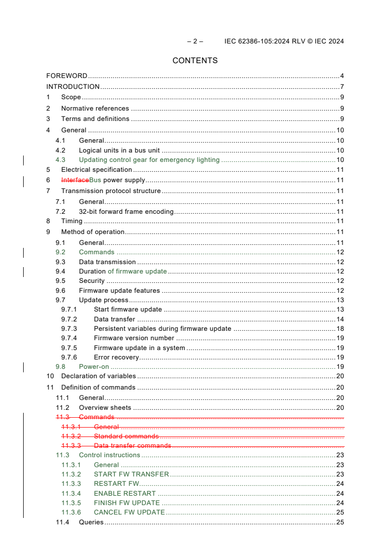
– 2 – IEC 62386-105:2024 RLV © IEC 2024
CONTENTS
FOREWORD . 4
INTRODUCTION . 7
1 Scope . 9
2 Normative references . 9
3 Terms and definitions . 9
4 General . 10
4.1 General . 10
4.2 Logical units in a bus unit . 10
4.3 Updating control gear for emergency lighting . 10
5 Electrical specification . 11
6 InterfaceBus power supply . 11
7 Transmission protocol structure . 11
7.1 General . 11
7.2 32-bit forward frame encoding . 11
8 Timing . 11
9 Method of operation . 11
9.1 General . 11
9.2 Commands . 12
9.3 Data transmission . 12
9.4 Duration of firmware update . 12
9.5 Security . 12
9.6 Firmware update features . 12
9.7 Update process . 13
9.7.1 Start firmware update . 13
9.7.2 Data transfer . 14
9.7.3 Persistent variables during firmware update . 18
9.7.4 Firmware version number . 19
9.7.5 Firmware update in a system . 19
9.7.6 Error recovery. 19
9.8 Power-on . 19
10 Declaration of variables . 20
11 Definition of commands . 20
11.1 General . 20
11.2 Overview sheets . 20
11.3 Commands .
11.3.1 General .
11.3.2 Standard commands .
11.3.3 Data transfer commands .
11.3 Control instructions . 23
11.3.1 General . 23
11.3.2 START FW TRANSFER . 23
11.3.3 RESTART FW. 24
11.3.4 ENABLE RESTART . 24
11.3.5 FINISH FW UPDATE . 24
11.3.6 CANCEL FW UPDATE . 25
11.4 Queries . 25
11.4.1 QUERY FW UPDATE FEATURES . 25
11.4.2 QUERY FW RESTART ENABLED . 25
11.4.3 QUERY FW UPDATE RECEIVER READY . 25
11.4.4 QUERY BLOCK INCOMPLETE OR FAULT . 25
11.4.5 QUERY FW TRANSFER VERSION . 26
11.4.6 QUERY BLOCK 0 ACCEPTED . 26
11.5 Data transfer commands . 26
11.5.1 General . 26
11.5.2 BEGIN BLOCK (data h, data m, data l) . 26
11.5.3 TRANSFER BLOCK DATA (data h, data m, data l) . 27
Annex A (normative) Update file description . 28
Annex B (normative) CRC16 calculation . 29
Annex C (informative) Firmware update process example . 30
Annex D (informative) Firmware update management check sheet . 35
Bibliography . 37
Figure 1 – IEC 62386 graphical overview . 7
Figure C.1 – Example of a firmware update process . 33
Table 1 – 32-bit command frame encoding . 11
Table 2 – Firmware update features . 13
Table 3 – Block 0 definitions . 14
Table 4 – Block 1.n definitions . 17
Table 5 – Declaration of additional variables . 20
Table 6 – Standard commands for bus units with firmware update capability . 21
Table 7 – Data transfer commands for bus units with firmware update capability . 21
Table D.1 – Example check sheet for firmware update of control gear . 35
– 4 – IEC 62386-105:2024 RLV © IEC 2024
INTERNATIONAL ELECTROTECHNICAL COMMISSION
____________
DIGITAL ADDRESSABLE LIGHTING INTERFACE –
Part 105: Particular requirements for control gear and control devices –
Firmware transfer
FOREWORD
1) The International Electrotechnical Commission (IEC) is a worldwide organization for standardization comprising
all national electrotechnical committees (IEC National Committees). The object of IEC is to promote international
co-operation on all questions concerning standardization in the electrical and electronic fields. To this end and
in addition to other activities, IEC publishes International Standards, Technical Specifications, Technical Reports,
Publicly Available Specifications (PAS) and Guides (hereafter referred to as "IEC Publication(s)"). Their
preparation is entrusted to technical committees; any IEC National Committee interested in the subject dealt with
may participate in this preparatory work. International, governmental and non-governmental organizations liaising
with the IEC also participate in this preparation. IEC collaborates closely with the International Organization for
Standardization (ISO) in accordance with conditions determined by agreement between the two organizations.
2) The formal decisions or agreements of IEC on technical matters express, as nearly as possible, an international
consensus of opinion on the relevant subjects since each technical committee has representation from all
interested IEC National Committees.
3) IEC Publications have the form of recommendations for international use and are accepted by IEC National
Committees in that sense. While all reasonable efforts are made to ensure that the technical content of IEC
Publications is accurate, IEC cannot be held responsible for the way in which they are used or for any
misinterpretation by any end user.
4) In order to promote international uniformity, IEC National Committees undertake to apply IEC Publications
transparently to the maximum extent possible in their national and regional publications. Any divergence between
any IEC Publication and the corresponding national or regional publication shall be clearly indicated in the latter.
5) IEC itself does not provide any attestation of conformity. Independent certification bodies provide conformity
assessment services and, in some areas, access to IEC marks of conformity. IEC is not responsible for any
services carried out by independent certification bodies.
6) All users should ensure that they have the latest edition of this publication.
7) No liability shall attach to IEC or its directors, employees, servants or agents including individual experts and
members of its technical committees and IEC National Committees for any personal injury, property damage or
other damage of any nature whatsoever, whether direct or indirect, or for costs (including legal fees) and
expenses arising out of the publication, use of, or reliance upon, this IEC Publication or any other IEC
Publications.
8) Attention is drawn to the Normative references cited in this publication. Use of the referenced publications is
indispensable for the correct application of this publication.
9) IEC draws attention to the possibility that the implementation of this document may involve the use of (a)
patent(s). IEC takes no position concerning the evidence, validity or applicability of any claimed patent rights in
respect thereof. As of the date of publication of this document, IEC had not received notice of (a) patent(s), which
may be required to implement this document. However, implementers are cautioned that this may not represent
the latest information, which may be obtained from the patent database available at https://patents.iec.ch. IEC
shall not be held responsible for identifying any or all such patent rights.
This redline version of the official IEC Standard allows the user to identify the changes
made to the previous edition IEC 62386-105:2020. A vertical bar appears in the margin
wherever a change has been made. Additions are in green text, deletions are in
strikethrough red text.
IEC 62386-105 has been prepared by IEC technical committee 34: Lighting. It is an International
Standard.
This second edition cancels and replaces the first edition published in 2020. This edition
constitutes a technical revision.
This edition includes the following significant technical changes with respect to the previous
edition:
a) several commands have been modified, renamed and added;
b) variables have been modified and added;
c) recommendations for implementation within emergency control gear have been added;
d) requirements for block acceptance have been changed;
e) example process-flow diagrams have been added;
f) requirements for restarting and power-on have been changed.
The text of this International Standard is based on the following documents:
Draft Report on voting
34/1258/FDIS 34/1281/RVD
Full information on the voting for its approval can be found in the report on voting indicated in
the above table.
The language used for the development of this International Standard is English.
This document was drafted in accordance with ISO/IEC Directives, Part 2, and developed in
accordance with ISO/IEC Directives, Part 1 and ISO/IEC Directives, IEC Supplement, available
at www.iec.ch/members_experts/refdocs. The main document types developed by IEC are
described in greater detail at www.iec.ch/publications.
This document is intended to be used in conjunction with:
• IEC 62386-101, which contains general requirements for system components;
• IEC 62386-102, which contains general requirements for the relevant product type (control
gear), and with the appropriate parts of the IEC 62386-2xx series (particular requirements
for control gear);
• IEC 62386-103, which contains general requirements for the relevant product type (control
devices), and with the appropriate parts of the IEC 62386-3xx series (particular
requirements for control devices);
• IEC 62386-104, which contains general requirements for wireless and alternative wired
system components.
A list of all parts in the IEC 62386 series, published under the general title Digital addressable
lighting interface, can be found on the IEC website.
– 6 – IEC 62386-105:2024 RLV © IEC 2024
The committee has decided that the contents of this document will remain unchanged until the
stability date indicated on the IEC website under webstore.iec.ch in the data related to the
specific document. At this date, the document will be
• reconfirmed,
• withdrawn, or
• revised.
IMPORTANT – The "colour inside" logo on the cover page of this document indicates
that it contains colours which are considered to be useful for the correct understanding
of its contents. Users should therefore print this document using a colour printer.
INTRODUCTION
IEC 62386 contains several parts, referred to as a series. The IEC 62386 series specifies a bus
system for control by digital signals of electronic lighting equipment. The IEC 62386-1xx series
includes the basic specifications. IEC 62386-101 contains general requirements for system
components, IEC 62386-102 extends this information with general requirements for control gear
and IEC 62386-103 extends it further with general requirements for control devices.
IEC 62386-104 and IEC 62386-105 can be applied to control gear or control devices.
IEC 62386-104 gives requirements for wireless and alternative wired system components.
IEC 62386-105 describes firmware transfer. IEC 62386-150 gives requirements for an auxiliary
power supply which can be stand-alone, or built into control gear or control devices.
The IEC 62386-2xx series extends the general requirements for control gear with lamp specific
extensions (mainly for backward compatibility with Edition 1 of IEC 62386) and with control gear
specific features.
The IEC 62386-3xx series extends the general requirements for control devices with input
device specific extensions describing the instance types as well as some common features that
can be combined with multiple instance types.
This first second edition of IEC 62386-105 is intended to be used in conjunction with
IEC 62386-101, IEC 62386-102 and the various parts that make up the IEC 62386-2xx series
for control gear, together with IEC 62386-103 and the various parts that make up the
IEC 62386-3xx series of particular requirements for control devices. The division into separately
published parts provides for ease of future amendments and revisions. Additional requirements
will be added as and when a need for them is recognized.
The setup of the standards is graphically represented in Figure 1 below.
Figure 1 – IEC 62386 graphical overview
When this document refers to any of the clauses of the IEC 62386-1xx series, the extent to
which such a clause is applicable and the order in which the tests are to be performed are is
specified. The other parts also include additional requirements, as necessary.
All numbers used in this document are decimal numbers unless otherwise noted. Hexadecimal
numbers are given in the format 0xVV, where VV is the value. Binary numbers are given in the
format XXXXXXXXb or in the format XXXX XXXX, where X is 0 or 1, "x" in binary numbers
means "don't care".
– 8 – IEC 62386-105:2024 RLV © IEC 2024
The following typographic expressions are used:
Variables: variableName or variableName[3:0], giving only bits 3 to 0 of variableName;
Range of values: [lowest, highest];
Command: "COMMAND NAME".
Function or command parameters: parameter name.
DIGITAL ADDRESSABLE LIGHTING INTERFACE –
Part 105: Particular requirements for control gear and control devices –
Firmware transfer
1 Scope
This part of IEC 62386 applies to control gear and control devices for control by digital signals
of electronic lighting equipment.
Typically, a bus unit according to the IEC 62386 series contains firmware. There are
circumstances where it might can be necessary to change the firmware after production or
shipping of the product, for example if the bus unit does not operate as intended. In such a
case, a firmware update of a bus unit via the interface is beneficial.
This firmware update process is primarily designed to be a bug fix process, not a feature
extension process. Nevertheless, the firmware update process can be used for feature
extensions. But it is important that the risk of negative effects to the complete system be
considered in detail.
NOTE Annex D provides a "Firmware update management check sheet" to support risk estimation.
2 Normative references
The following documents are referred to in the text in such a way that some or all of their content
constitutes requirements of this document. For dated references, only the edition cited applies.
For undated references, the latest edition of the referenced document (including any
amendments) applies.
IEC 62386-101:20142022, Digital addressable lighting interface – Part 101: General
requirements – System components
IEC 62386-101:2014/AMD1:2018
IEC 62386-102:20142022, Digital addressable lighting interface – Part 102: General
requirements – Control gear
IEC 62386-102:2014/AMD1:2018
IEC 62386-103:20142022, Digital addressable lighting interface – Part 103: General
requirements – Control devices
IEC 62386-103:2014/AMD1:2018
3 Terms and definitions
For the purposes of this document, the terms and definitions given in IEC 62386-101,
IEC 62386-102, IEC 62386-103 and the following apply.
ISO and IEC maintain terminology databases for use in standardization at the following
addresses:
• IEC Electropedia: available at https://www.electropedia.org/
• ISO Online browsing platform: available at https://www.iso.org/obp
– 10 – IEC 62386-105:2024 RLV © IEC 2024
3.1
FW
firmware
software programmed into a control gear or control device
Note 1 to entry: Firmware can be changed during an update.
Note 1 to entry: This note applies to the French language only.
3.2
CRC
cyclic redundancy check
checksum used to prevent data corruption
Note 1 to entry: Annex B provides detailed information about CRC calculation.
3.3
block
unit of data containing information
Note 1 to entry: Information in a firmware update block usually contains firmware content.
3.4
programming
writing firmware transfer data to non-volatile memory (NVM)
3.5
normal operation
operation according to IEC 62386-102 or IEC 62386-103
4 General
4.1 General
The requirements of IEC 62386-101:2014 and IEC 62386-101:2014/AMD1:20182022, Clause 4
apply, with the restrictions, changes and additions identified below.
NOTE Systems with a single-master application controller are unlikely to operate correctly when other master
control devices, such as upgrade firmware update tools, are connected.
4.2 Transmitters and receivers in bus units
The requirements of IEC 62386-101:2014 and IEC 62386-101:2014/AMD1:2018, 4.6.1 shall be
extended as follows.
Bus units supporting firmware transfer shall be additionally capable of receiving 32 bit forward
frames as specified in IEC 62386-101:2014, 7.4.3 (Reserved forward frame).
4.2 Logical units in a bus unit
If the firmware update process is started on a bus unit, all logical units inside the bus unit shall
be affected. All variables defined in Table 5 shall be shared by all logical units of the bus unit.
Commands addressed to one or more logical units within the bus unit shall be accepted by the
bus unit according to the requirements of 9.2.
4.3 Updating control gear for emergency lighting
If IEC 62386-105 is implemented in control gear for emergency lighting, the product manual or
data sheet should include guidance on the safety implications of a firmware update that should
be considered.
5 Electrical specification
The requirements of IEC 62386-101:2014 and IEC 62386-101:2014/AMD1:20182022, Clause 5
apply.
6 InterfaceBus power supply
The requirements of IEC 62386-101:2014 and IEC 62386-101:2014/AMD1:20182022, Clause 6
apply.
7 Transmission protocol structure
7.1 General
The requirements of IEC 62386-101:20142022, Clause 7 apply, with the following additions.
7.2 32-bit forward frame encoding
The forward frame format used for firmware update consists of n = 32 data bits as described in
IEC 62386-101:20142022, 7.4.3 (Reserved 32-bit forward frame).
For commands, the 32-bit forward frame for 32 bit frames shall be encoded as shown in Table 1.
Table 1 – 32-bit command frame encoding
Bytes/Bits
Opcode byte
Address byte
Device addressing method
1 2 3
a
31 30 29 28 27 26 25 23…16 15…8 7…0
0 64 short addresses x Short addressing
b
1 0 1 1 1 1 0 1 Data transfer command
b
1 1 0 0 1 0 1 1 Data transfer command
1 1 1 1 1 1 0 x Broadcast unaddressed
1 1 1 1 1 1 1 x Broadcast
All other address byte values Reserved
a
For bit 24 Where bit 24 is shown as "x", 0 indicates address space for control gear, 1 indicates address space
for control devices.
b
See Table 7 for data transfer commands.
8 Timing
The requirements of IEC 62386-101:2014 and IEC 62386-101:2014/AMD1:20182022, Clause 8
apply.
9 Method of operation
9.1 General
The requirements of IEC 62386-101:2014 and IEC 62386-101:2014/AMD1:2018, 9.8 (Dealing
with frames and commands), 9.2 (Transactions) with the exception that the total duration may
exceed 400 ms, 9.4 (Command iteration) and 9.6 (Use of multiple bus power supplies) apply.
– 12 – IEC 62386-105:2024 RLV © IEC 2024
The requirements of IEC 62386-101:2022, Clause 9 apply, with the exception that the total
duration of a transaction may exceed 400 ms (IEC 62386-101:2022, 9.3).
9.2 Commands
A bus unit shall check the device addressing scheme to see if it is addressed by a command.
The bus unit shall accept the command, unless any of the following conditions hold:
• The command is sent using short address, broadcast addressing or broadcast unaddressed
addressing, and bit 24 of the command frame does not match the type of bus unit (control
gear or control device).
• The command is sent using short addressing and the given short address is not equal to its
short address.
• The command is sent using reserved addressing.
• The command is sent using broadcast unaddressed addressing and the short address is not
MASK.
• The command is not defined (e.g. reserved command).
The following command groups can be identified:
• standard commands;
– instructions;
– queries;
• data transfer commands.
9.3 Data transmission
A bus unit receives a new FW block by block. The first block (block 0) contains information
about the type of bus unit (see Table 3), which receives a new FW. This avoids transferring the
wrong FW to a bus unit if more than one bus unit is updated at a time.
NOTE Annex A provides detailed information about the update file.
The opcode byte 1 shall be 0xFB for 32-bit standard commands (see Table 6). If the opcode
byte 1 in a standard command is not equal to 0xFB, the bus unit shall not accept the standard
command.
The update file shall contain release notes as described in Annex A.
9.4 Duration of firmware update
A data transmission frame consists of a start bit, a 32-bit data bits transfer command and a stop
condition, which occupies the bus for around 30 ms. With a settling time of less than 15 ms
(maximum frame priority) (priority 1 settling time), the transmission of three bytes takes less
than 45 ms. For an update of 64 kByte kB it is expected to take less than 20 min.
9.5 Security
This document specifies the use of CRC checksums to help ensure error-free transfer of data.
In addition, it is recommended that the individual manufacturer ensures firmware image integrity
and authenticity, for example by making use of the device key.
9.6 Firmware update features
Each bus unit shall expose its firmware update features as a combination of device properties
as given in Table 2.
Table 2 – Firmware update features
Bit Description Value See
0 "fwUpdateCancelSupported" is TRUE? "1" = "YES" XXX
9.7.2.3
1 Integrated bus power supply is present "1" = "YES"
and is disabled during firmware update
"0" = bus power supply state is unchanged
during firmware update, or is not present
1-2 to Reserved – Not implemented "0" = "NO"
The bus unit firmware update features can be queried using QUERY FW UPDATE FEATURES.
If the bus unit supports cancellation of the firmware update process (see 9.6.2.3),
“fwUpdateCancelSupported” is set to TRUE.
Bit 1: "1" shall indicate that an integrated bus power supply is present and is automatically
disabled during the firmware update process. "0" shall indicate that either there is no integrated
bus power supply, or if there is an integrated bus power supply then its state shall not be
automatically changed when starting, during, or at the end of the firmware update. To help
prevent loss of bus power during a firmware update, a lock-out mechanism is described in
11.3.2.
NOTE For bus units with bit 1 = "1", using a firmware update tool that is unable to apply suitable bus power can
result in a system with no bus power and so no communications are possible. In such cases, a bus power supply can
be temporarily connected to the system to allow the firmware update process to continue.
9.7 Update process
9.7.1 Start firmware update
A bus unit shall enable the firmware update process by the acceptance of the command
START FW TRANSFER. Several bus units can be addressed in this way to update more than
one bus unit at a time.
A bus unit shall enable the firmware update process whenever "fwUpdateProcessEnabled" is
TRUE. This can be due to execution of the command START FW TRANSFER, or after a power
cycle where the previous update failed (see Table 5). Several bus units can be addressed in
this way to update more than one bus unit at a time.
NOTE 1 Annex C provides an example of the firmware update process.
It is recommended not to trigger erasing of the memory before block 0 is verified.
The bus unit shall be capable of returning to normal operation until at least a block 0 has been
successfully verified.
NOTE 2 This means that bus units with a single flash image of the firmware used for normal operation cannot erase
that firmware until at least block 0 has been verified.
Whilst "fwUpdateProcessEnabled" is TRUE, the operation of the bus unit is manufacturer-specific
except for the requirements given in this document.
NOTE 3 This includes, for example, the reaction to commands of other parts of the IEC 62386 series.
– 14 – IEC 62386-105:2024 RLV © IEC 2024
9.7.2 Data transfer
9.7.2.1 Block 0 (information block)
Block 0 contains all data for the bus unit to decide if it will accept the new firmware or not.
The global trade item number (GTIN), the hardware version number and the firmware version
number contained in the bus unit are described in IEC 62386-102:2014 and IEC 62386-
102:2014/AMD1:20182022, 9.10.67 (Memory bank 0 for control gear) and IEC 62386-103:2014
and IEC 62386-103:2014/AMD1:20182022, 9.10.69.11.7 (Memory bank 0 for control devices).
A bus unit shall have a maximum of one family GTIN which shall be shown in the documentation
of the bus unit.
If "currentBlock" is 0, then upon reception of a complete block 0, the following information is
shall be checked, where Table 3 shows block 0 content:
• The received block 0 "Size of block" is equal to the value shown in Table 3.
• The received block 0 "Session key" is not MASK or 0.
• The received block 0 "Block number" is equal to the value shown in Table 3.
• The received block 0 "Block 0 version" is equal to the value shown in Table 3.
• The received block 0 "GTIN" matches the GTIN stored in memory bank 0.
• (Received block 0 "FW version min") ≤ (memory bank 0, Firmware version) ≤ (received block
0 "FW version max").
• (Received block 0 "HW version min") ≤ (memory bank 0, Hardware version) ≤ (received
block 0 "HW version max").
• (Received block 0 "Identification number min") ≤ (memory bank 0, Identification number) ≤
(received block 0 "Identification number max").
• The received block 0 "Device key" meets manufacturer-specific requirements.
• The received block 0 "CRC" matches the calculated value based on the block 0 content;
Annex B is applicable).
If the above check is successful, the following operation shall result:
• "sessionKey" shall be set to the received block 0 "Session key",
• “currentBlock” shall be set to 1,
• “currentBlockByte” shall be set to 0,
• previously received block data that is unwritten may be discarded.
Otherwise, the following operation shall result:
• “fwUpdateProcessEnabled” shall be set to FALSE and resume normal operation if possible.
• The block 0 content shall be discarded.
NOTE In the case where block 0 content is discarded, "fwUpdateProcessEnabled" remains TRUE, so the bus unit will
continue looking for valid block 0 data. This enables multiple devices to be updated, even where these devices use
identical firmware but have different GTINs, due to the possibility of an update tool sending multiple block 0s.
Table 3 – Block 0 definitions
Address (hex) Size (bytes) Description
00 1 Size of block (fixed value of 0x3D for block 0)
01 1 Block 0 version (always 0x00)
a
02.04 3
Total block count (MSB first)
05.0A 6 GTIN (MSB first)
0B.0C 2 HW version min (MSB first)
0D.0E 2 HW version max (MSB first)
0F.10 2 FW version min (MSB first)
11.12 2 FW version max (MSB first)
13. 1A 8 Identification number min (MSB first)
1B.22 8 Identification number max (MSB first)
b
23.2A 8
Session key
c
2B.3A 16
Device key
3B.3C 2 CRC (MSB first)
a
This is the amount of blocks being transferred during the firmware update.
b
The session key is generated by the bus unit, which transfers the firmware update.
c
The device key and its use is manufacturer-specific. It allows the manufacturer to
specify different areas/options in his firmware.
Offset (hex) Size (bytes) Description
00.01 2 Size of block 0 (MSB first, fixed value of 0x0041 for block 0)
a
02.09 8
Session key
0A.0C 3 Block number (always 0x000000 for block 0)
0D 1 Block 0 version (always 0x01)
b
0E.10 3
Total block count (MSB first)
11.16 6 GTIN (MSB first)
17.18 2 HW version min (MSB first)
19.1A 2 HW version max (MSB first)
1B.1C 2 FW version min (MSB first)
1D.1E 2 FW version max (MSB first)
1F.26 8 Identification number min (MSB first)
27.2E 8 Identification number max (MSB first)
c
2F.3E 16
Device key
3F.40 2 CRC (MSB first)
Key
MSB Most significant byte
a
The session key is generated by the FW update tool which transfers the firmware update.
b
This is the number of blocks, excluding block 0, being transferred during the firmware update.
c
The device key and its use is manufacturer-specific. It allows the manufacturer to specify different areas or
options in their firmware. The device key shall be independent of the session key, allowing a firmware update
tool to change the session key without requiring a change to the device key.
– 16 – IEC 62386-105:2024 RLV © IEC 2024
It is recommended to calculate the CRC checksums with the incoming bytes to minimize delay
at the end of the block reception.
9.7.2.2 Block 1.n (data block)
A bus unit shall only accept a block, if the following condition is true:
• “fwUpdateProcessEnabled” is TRUE, and
• The session key matches the received block 0 “Session key”.
After reception of a whole block, the consistency of the firmware data inside the block shall be
verified by CRC (address 0D.0E). The data consistency of the whole block shall be verified by
a second CRC (address s+0F…s+10). If the verification fails, the bus unit shall discard the
block. If a block is valid, but is the same as the last programmed block, it is recommended to
discard the block to prevent unnecessary write cycles.
Table 4 shows the content of a data block. A bus unit shall only accept a data block if the
following conditions are true:
• "fwUpdateProcessEnabled" is TRUE, and
• the session key matches "sessionKey", and is not MASK or 0, and
• the block number matches "currentBlock", and
• "currentBlock" is not 0.
After reception of a whole block, the consistency of the firmware data inside the block shall be
verified by CRC (offset 0x0D.0x0E). The data consistency of the whole block shall be verified
by a second CRC (offset s + 0x0F…s + 0x10). The block may optionally be discarded if "size of
whole block" is an unexpected size, as determined by the manufacturer. If the verification fails,
the bus unit shall discard the block. If a block is valid, but is the same as the last programmed
block, it is recommended to discard the block to prevent unnecessary write cycles.
Table 4 – Block 1.n definitions
Address (hex) Size (bytes) Description
00.01 2 s = Size of block data bytes (MSB first)
02.09 8 Session key
0A.0C 3 Block number (MSB first)
0D.0E 2 CRC (of block data bytes)
0F.(s+0E) s Firmware data (optionally encrypted by
manufacturer)
s+0F.s+10 2 CRC (of total block)
NOTE This allows a theoretical maximum of 65 535 bytes of firmware data per block,
resulting in a maximum total of 65 552 bytes in the block.
Offset (hex) Size (bytes) Description
a b
00.01 2
Size of whole block (MSB first)
02.09 8 Session key
0A.0C 3 Block number (MSB first)
0D.0E 2 CRC (of block firmware data bytes)
0F.(s + 0E) s Firmware data bytes (optionally encrypted by manufacturer)
(s + 0F).(s + 10) 2 CRC (of whole block)
Key
MSB Most significant byte
a
This allows a theoretical maximum block size of 65 535 bytes, resulting in a maximum firmware data size of
65 518 bytes.
b
Whole block size = s + 17.
It is recommended to calculate the CRC checksums with the incoming bytes to minimize delay
at the end of the block reception.
9.7.2.3 Cancel firmware update
If a bus unit physically supports cancellation of FW updates and can return to the previous FW,
the bus unit shall respond to QUERY FW UPDATE FEATURES with 00000001b.
If a bus unit supports cancellation of the FW updates, the bus unit shall set
"fwUpdateProcessEnabled" to FALSE by the acceptance of the command CANCEL FW UPDATE.
If a bus unit physically does not support a cancellation of the FW update process, it shall ignore
this command.
If the bus unit supports cancellation of the firmware update process even when "sessionKey" is
not MASK, "fwUpdateCancelSupported" shall be TRUE.
In this case, the command CANCEL FW UPDATE can be used to cancel the firmware update
at any time and return the bus unit to normal operation.
– 18 – IEC 62386-105:2024 RLV © IEC 2024
9.7.3 Persistent variables during firmware update
A firmware update may totally change the internal structure memory arrangement and content
of the corresponding bus unit, except for the following cases:
The values for
• the GTIN,
• the identification number,
• the hardware version,
shall not be affected by a firmware update.
If a bus unit operates in the standard mode described as operating mode 0x00 in
IEC 62386‑102:2014 and IEC 62386-102:2014/AMD1:2018, 9.10 for control gear and in
IEC 62386-103:2014 and IEC 62386-103:2014/AMD1:2018, 9.10.5 for control devices, each
NVM variable shall either remain unchanged or be set to factory default as a result of a firmware
update. the short addresses of all logical units shall be maintained at least until the firmware
update successfully completes. For a bus unit in an operating mode different from 0x00, the
variables do not need to be in factory default state.
If firmware update features bit 1 is "0", the enabled or disabled state of an integrated bus power
supply shall not be changed by a firmware update (see 9.6).
For the purposes of this Subclause 9.7.3, a "structural change" in the bus unit is when any of
the following are changed by the firmware update:
• number of logical units, or
• implemented device types, or
• quantity or types of implemented input device instances, or
• implemented feature types.
NOTE 1 A change in "current bus unit configuration" in memory bank 0 can cause a change of these "structural
change" parameters.
The short addresses of all logical units shall not change as a result of a firmware update with a
new firmware image until a restart with the new firmware image is carried out. If the restart with
the new firmware image results in a structural change of the bus unit, then the short addresses
of all logical units shall be set to MASK and it is recommended that all NVM variables are set
to their factory defaults. If instead, the restart with a new firmware image results in no structural
change of the bus unit, the short addresses of all logical units shall remain unchanged and it is
recommended that all NVM variables are unchanged.
The manufacturer shall provide a document stipulating which variables are affected by the
update and whether a re-commissioning of the system is necessary after the firmware update
process.
After a firmware update, an updated bus unit should first proceed to a power-up sequence to
(re-)load RAM variables.
It is recommended that all NVM variables remain unchanged as a result of the firmware update.
NOTE 2 Owing to the fact that the programme memory of a bus unit is updated, values in other parts of the
IEC 62386 series marked as ROM can be changed.
9.7.4 Firmware version number
It is allowed permitted to transfer the same firmwar
...
IEC 62386-105 ®
Edition 2.0 2024-12
INTERNATIONAL
STANDARD
NORME
INTERNATIONALE
Digital addressable lighting interface –
Part 105: Particular requirements for control gear and control devices –
Firmware transfer
Interface d'éclairage adressable numérique –
Partie 105: Exigences particulières pour appareillages et dispositifs de
commande – Transfert du microprogramme
All rights reserved. Unless otherwise specified, no part of this publication may be reproduced or utilized in any form
or by any means, electronic or mechanical, including photocopying and microfilm, without permission in writing from
either IEC or IEC's member National Committee in the country of the requester. If you have any questions about IEC
copyright or have an enquiry about obtaining additional rights to this publication, please contact the address below or
your local IEC member National Committee for further information.
Droits de reproduction réservés. Sauf indication contraire, aucune partie de cette publication ne peut être reproduite ni
utilisée sous quelque forme que ce soit et par aucun procédé, électronique ou mécanique, y compris la photocopie et
les microfilms, sans l'accord écrit de l'IEC ou du Comité national de l'IEC du pays du demandeur. Si vous avez des
questions sur le copyright de l'IEC ou si vous désirez obtenir des droits supplémentaires sur cette publication, utilisez
les coordonnées ci-après ou contactez le Comité national de l'IEC de votre pays de résidence.
IEC Secretariat Tel.: +41 22 919 02 11
3, rue de Varembé info@iec.ch
CH-1211 Geneva 20 www.iec.ch
Switzerland
About the IEC
The International Electrotechnical Commission (IEC) is the leading global organization that prepares and publishes
International Standards for all electrical, electronic and related technologies.
About IEC publications
The technical content of IEC publications is kept under constant review by the IEC. Please make sure that you have the
latest edition, a corrigendum or an amendment might have been published.
IEC publications search - webstore.iec.ch/advsearchform IEC Products & Services Portal - products.iec.ch
The advanced search enables to find IEC publications by a Discover our powerful search engine and read freely all the
variety of criteria (reference number, text, technical publications previews, graphical symbols and the glossary.
committee, …). It also gives information on projects, replaced With a subscription you will always have access to up to date
and withdrawn publications. content tailored to your needs.
IEC Just Published - webstore.iec.ch/justpublished
Electropedia - www.electropedia.org
Stay up to date on all new IEC publications. Just Published
The world's leading online dictionary on electrotechnology,
details all new publications released. Available online and once
containing more than 22 500 terminological entries in English
a month by email.
and French, with equivalent terms in 25 additional languages.
Also known as the International Electrotechnical Vocabulary
IEC Customer Service Centre - webstore.iec.ch/csc
(IEV) online.
If you wish to give us your feedback on this publication or need
further assistance, please contact the Customer Service
Centre: sales@iec.ch.
A propos de l'IEC
La Commission Electrotechnique Internationale (IEC) est la première organisation mondiale qui élabore et publie des
Normes internationales pour tout ce qui a trait à l'électricité, à l'électronique et aux technologies apparentées.
A propos des publications IEC
Le contenu technique des publications IEC est constamment revu. Veuillez vous assurer que vous possédez l’édition la
plus récente, un corrigendum ou amendement peut avoir été publié.
Recherche de publications IEC - IEC Products & Services Portal - products.iec.ch
webstore.iec.ch/advsearchform Découvrez notre puissant moteur de recherche et consultez
La recherche avancée permet de trouver des publications IEC gratuitement tous les aperçus des publications, symboles
en utilisant différents critères (numéro de référence, texte, graphiques et le glossaire. Avec un abonnement, vous aurez
comité d’études, …). Elle donne aussi des informations sur les toujours accès à un contenu à jour adapté à vos besoins.
projets et les publications remplacées ou retirées.
Electropedia - www.electropedia.org
IEC Just Published - webstore.iec.ch/justpublished
Le premier dictionnaire d'électrotechnologie en ligne au monde,
Restez informé sur les nouvelles publications IEC. Just
avec plus de 22 500 articles terminologiques en anglais et en
Published détaille les nouvelles publications parues.
français, ainsi que les termes équivalents dans 25 langues
Disponible en ligne et une fois par mois par email.
additionnelles. Egalement appelé Vocabulaire
Electrotechnique International (IEV) en ligne.
Service Clients - webstore.iec.ch/csc
Si vous désirez nous donner des commentaires sur cette
publication ou si vous avez des questions contactez-nous:
sales@iec.ch.
IEC 62386-105 ®
Edition 2.0 2024-12
INTERNATIONAL
STANDARD
NORME
INTERNATIONALE
Digital addressable lighting interface –
Part 105: Particular requirements for control gear and control devices –
Firmware transfer
Interface d'éclairage adressable numérique –
Partie 105: Exigences particulières pour appareillages et dispositifs de
commande – Transfert du microprogramme
INTERNATIONAL
ELECTROTECHNICAL
COMMISSION
COMMISSION
ELECTROTECHNIQUE
INTERNATIONALE
ICS 29.140.50, 29.140.99 ISBN 978-2-8327-0053-2
– 2 – IEC 62386-105:2024 © IEC 2024
CONTENTS
FOREWORD . 4
INTRODUCTION . 6
1 Scope . 8
2 Normative references . 8
3 Terms and definitions . 8
4 General . 9
4.1 General . 9
4.2 Logical units in a bus unit . 9
4.3 Updating control gear for emergency lighting . 9
5 Electrical specification . 9
6 Bus power supply . 9
7 Transmission protocol structure . 10
7.1 General . 10
7.2 32-bit forward frame encoding . 10
8 Timing . 10
9 Method of operation . 10
9.1 General . 10
9.2 Commands . 10
9.3 Data transmission . 11
9.4 Duration of firmware update . 11
9.5 Security . 11
9.6 Firmware update features . 11
9.7 Update process . 12
9.7.1 Start firmware update . 12
9.7.2 Data transfer . 12
9.7.3 Persistent variables during firmware update . 14
9.7.4 Firmware version number . 15
9.7.5 Firmware update in a system . 15
9.7.6 Error recovery. 15
9.8 Power-on . 15
10 Declaration of variables . 16
11 Definition of commands . 16
11.1 General . 16
11.2 Overview sheets . 16
11.3 Control instructions . 17
11.3.1 General . 17
11.3.2 START FW TRANSFER . 17
11.3.3 RESTART FW. 18
11.3.4 ENABLE RESTART . 18
11.3.5 FINISH FW UPDATE . 18
11.3.6 CANCEL FW UPDATE . 19
11.4 Queries . 19
11.4.1 QUERY FW UPDATE FEATURES . 19
11.4.2 QUERY FW RESTART ENABLED . 19
11.4.3 QUERY FW UPDATE RECEIVER READY . 19
11.4.4 QUERY BLOCK INCOMPLETE OR FAULT . 20
11.4.5 QUERY FW TRANSFER VERSION . 20
11.4.6 QUERY BLOCK 0 ACCEPTED . 20
11.5 Data transfer commands . 20
11.5.1 General . 20
11.5.2 BEGIN BLOCK (data h, data m, data l) . 20
11.5.3 TRANSFER BLOCK DATA (data h, data m, data l) . 21
Annex A (normative) Update file description . 22
Annex B (normative) CRC16 calculation . 23
Annex C (informative) Firmware update process example . 24
Annex D (informative) Firmware update management check sheet . 28
Bibliography . 30
Figure 1 – IEC 62386 graphical overview . 6
Figure C.1 – Example of a firmware update process . 26
Table 1 – 32-bit command frame encoding . 10
Table 2 – Firmware update features . 11
Table 3 – Block 0 definitions . 13
Table 4 – Block 1.n definitions . 14
Table 5 – Declaration of variables . 16
Table 6 – Standard commands. 17
Table 7 – Data transfer commands . 17
Table D.1 – Example check sheet for firmware update of control gear . 28
– 4 – IEC 62386-105:2024 © IEC 2024
INTERNATIONAL ELECTROTECHNICAL COMMISSION
____________
DIGITAL ADDRESSABLE LIGHTING INTERFACE –
Part 105: Particular requirements for control gear and control devices –
Firmware transfer
FOREWORD
1) The International Electrotechnical Commission (IEC) is a worldwide organization for standardization comprising
all national electrotechnical committees (IEC National Committees). The object of IEC is to promote international
co-operation on all questions concerning standardization in the electrical and electronic fields. To this end and
in addition to other activities, IEC publishes International Standards, Technical Specifications, Technical Reports,
Publicly Available Specifications (PAS) and Guides (hereafter referred to as "IEC Publication(s)"). Their
preparation is entrusted to technical committees; any IEC National Committee interested in the subject dealt with
may participate in this preparatory work. International, governmental and non-governmental organizations liaising
with the IEC also participate in this preparation. IEC collaborates closely with the International Organization for
Standardization (ISO) in accordance with conditions determined by agreement between the two organizations.
2) The formal decisions or agreements of IEC on technical matters express, as nearly as possible, an international
consensus of opinion on the relevant subjects since each technical committee has representation from all
interested IEC National Committees.
3) IEC Publications have the form of recommendations for international use and are accepted by IEC National
Committees in that sense. While all reasonable efforts are made to ensure that the technical content of IEC
Publications is accurate, IEC cannot be held responsible for the way in which they are used or for any
misinterpretation by any end user.
4) In order to promote international uniformity, IEC National Committees undertake to apply IEC Publications
transparently to the maximum extent possible in their national and regional publications. Any divergence between
any IEC Publication and the corresponding national or regional publication shall be clearly indicated in the latter.
5) IEC itself does not provide any attestation of conformity. Independent certification bodies provide conformity
assessment services and, in some areas, access to IEC marks of conformity. IEC is not responsible for any
services carried out by independent certification bodies.
6) All users should ensure that they have the latest edition of this publication.
7) No liability shall attach to IEC or its directors, employees, servants or agents including individual experts and
members of its technical committees and IEC National Committees for any personal injury, property damage or
other damage of any nature whatsoever, whether direct or indirect, or for costs (including legal fees) and
expenses arising out of the publication, use of, or reliance upon, this IEC Publication or any other IEC
Publications.
8) Attention is drawn to the Normative references cited in this publication. Use of the referenced publications is
indispensable for the correct application of this publication.
9) IEC draws attention to the possibility that the implementation of this document may involve the use of (a)
patent(s). IEC takes no position concerning the evidence, validity or applicability of any claimed patent rights in
respect thereof. As of the date of publication of this document, IEC had not received notice of (a) patent(s), which
may be required to implement this document. However, implementers are cautioned that this may not represent
the latest information, which may be obtained from the patent database available at https://patents.iec.ch. IEC
shall not be held responsible for identifying any or all such patent rights.
IEC 62386-105 has been prepared by IEC technical committee 34: Lighting. It is an International
Standard.
This second edition cancels and replaces the first edition published in 2020. This edition
constitutes a technical revision.
This edition includes the following significant technical changes with respect to the previous
edition:
a) several commands have been modified, renamed and added;
b) variables have been modified and added;
c) recommendations for implementation within emergency control gear have been added;
d) requirements for block acceptance have been changed;
e) example process-flow diagrams have been added;
f) requirements for restarting and power-on have been changed.
The text of this International Standard is based on the following documents:
Draft Report on voting
34/1258/FDIS 34/1281/RVD
Full information on the voting for its approval can be found in the report on voting indicated in
the above table.
The language used for the development of this International Standard is English.
This document was drafted in accordance with ISO/IEC Directives, Part 2, and developed in
accordance with ISO/IEC Directives, Part 1 and ISO/IEC Directives, IEC Supplement, available
at www.iec.ch/members_experts/refdocs. The main document types developed by IEC are
described in greater detail at www.iec.ch/publications.
This document is intended to be used in conjunction with:
• IEC 62386-101, which contains general requirements for system components;
• IEC 62386-102, which contains general requirements for the relevant product type (control
gear), and with the appropriate parts of the IEC 62386-2xx series (particular requirements
for control gear);
• IEC 62386-103, which contains general requirements for the relevant product type (control
devices), and with the appropriate parts of the IEC 62386-3xx series (particular
requirements for control devices);
• IEC 62386-104, which contains general requirements for wireless and alternative wired
system components.
A list of all parts in the IEC 62386 series, published under the general title Digital addressable
lighting interface, can be found on the IEC website.
The committee has decided that the contents of this document will remain unchanged until the
stability date indicated on the IEC website under webstore.iec.ch in the data related to the
specific document. At this date, the document will be
• reconfirmed,
• withdrawn, or
• revised.
IMPORTANT – The "colour inside" logo on the cover page of this document indicates
that it contains colours which are considered to be useful for the correct understanding
of its contents. Users should therefore print this document using a colour printer.
– 6 – IEC 62386-105:2024 © IEC 2024
INTRODUCTION
IEC 62386 contains several parts, referred to as a series. The IEC 62386 series specifies a bus
system for control by digital signals of electronic lighting equipment. The IEC 62386-1xx series
includes the basic specifications. IEC 62386-101 contains general requirements for system
components, IEC 62386-102 extends this information with general requirements for control gear
and IEC 62386-103 extends it further with general requirements for control devices.
IEC 62386-104 and IEC 62386-105 can be applied to control gear or control devices.
IEC 62386-104 gives requirements for wireless and alternative wired system components.
IEC 62386-105 describes firmware transfer. IEC 62386-150 gives requirements for an auxiliary
power supply which can be stand-alone, or built into control gear or control devices.
The IEC 62386-2xx series extends the general requirements for control gear with lamp specific
extensions (mainly for backward compatibility with Edition 1 of IEC 62386) and with control gear
specific features.
The IEC 62386-3xx series extends the general requirements for control devices with input
device specific extensions describing the instance types as well as some common features that
can be combined with multiple instance types.
This second edition of IEC 62386-105 is intended to be used in conjunction with IEC 62386-101,
IEC 62386-102 and the various parts that make up the IEC 62386-2xx series for control gear,
together with IEC 62386-103 and the various parts that make up the IEC 62386-3xx series of
particular requirements for control devices. The division into separately published parts
provides for ease of future amendments and revisions. Additional requirements will be added
as and when a need for them is recognized.
The setup of the standards is graphically represented in Figure 1 below.
Figure 1 – IEC 62386 graphical overview
When this document refers to any of the clauses of the IEC 62386-1xx series, the extent to
which such a clause is applicable is specified. The other parts also include additional
requirements, as necessary.
All numbers used in this document are decimal numbers unless otherwise noted. Hexadecimal
numbers are given in the format 0xVV, where VV is the value. Binary numbers are given in the
format XXXXXXXXb or in the format XXXX XXXX, where X is 0 or 1, "x" in binary numbers
means "don't care".
The following typographic expressions are used:
Variables: variableName or variableName[3:0], giving only bits 3 to 0 of variableName;
Range of values: [lowest, highest];
Command: "COMMAND NAME".
Function or command parameters: parameter name.
– 8 – IEC 62386-105:2024 © IEC 2024
DIGITAL ADDRESSABLE LIGHTING INTERFACE –
Part 105: Particular requirements for control gear and control devices –
Firmware transfer
1 Scope
This part of IEC 62386 applies to control gear and control devices for control by digital signals
of electronic lighting equipment.
Typically, a bus unit according to the IEC 62386 series contains firmware. There are
circumstances where it can be necessary to change the firmware after production or shipping
of the product, for example if the bus unit does not operate as intended. In such a case, a
firmware update of a bus unit via the interface is beneficial.
This firmware update process is primarily designed to be a bug fix process, not a feature
extension process. Nevertheless, the firmware update process can be used for feature
extensions. But it is important that the risk of negative effects to the complete system be
considered in detail.
NOTE Annex D provides a "Firmware update management check sheet" to support risk estimation.
2 Normative references
The following documents are referred to in the text in such a way that some or all of their content
constitutes requirements of this document. For dated references, only the edition cited applies.
For undated references, the latest edition of the referenced document (including any
amendments) applies.
IEC 62386-101:2022, Digital addressable lighting interface – Part 101: General requirements –
System components
IEC 62386-102:2022, Digital addressable lighting interface – Part 102: General requirements –
Control gear
IEC 62386-103:2022, Digital addressable lighting interface – Part 103: General requirements –
Control devices
3 Terms and definitions
For the purposes of this document, the terms and definitions given in IEC 62386-101,
IEC 62386-102, IEC 62386-103 and the following apply.
ISO and IEC maintain terminology databases for use in standardization at the following
addresses:
• IEC Electropedia: available at https://www.electropedia.org/
• ISO Online browsing platform: available at https://www.iso.org/obp
3.1
FW
firmware
software programmed into a control gear or control device
Note 1 to entry: Firmware can be changed during an update.
3.2
CRC
cyclic redundancy check
checksum used to prevent data corruption
Note 1 to entry: Annex B provides detailed information about CRC calculation.
3.3
block
unit of data containing information
Note 1 to entry: Information in a firmware update block usually contains firmware content.
3.4
programming
writing firmware transfer data to non-volatile memory (NVM)
3.5
normal operation
operation according to IEC 62386-102 or IEC 62386-103
4 General
4.1 General
The requirements of IEC 62386-101:2022, Clause 4 apply, with the restrictions, changes and
additions identified below.
NOTE Systems with a single-master application controller are unlikely to operate correctly when other master
control devices, such as firmware update tools, are connected.
4.2 Logical units in a bus unit
If the firmware update process is started on a bus unit, all logical units inside the bus unit shall
be affected. All variables defined in Table 5 shall be shared by all logical units of the bus unit.
Commands addressed to one or more logical units within the bus unit shall be accepted by the
bus unit according to the requirements of 9.2.
4.3 Updating control gear for emergency lighting
If IEC 62386-105 is implemented in control gear for emergency lighting, the product manual or
data sheet should include guidance on the safety implications of a firmware update that should
be considered.
5 Electrical specification
The requirements of IEC 62386-101:2022, Clause 5 apply.
6 Bus power supply
The requirements of IEC 62386-101:2022, Clause 6 apply.
– 10 – IEC 62386-105:2024 © IEC 2024
7 Transmission protocol structure
7.1 General
The requirements of IEC 62386-101:2022, Clause 7 apply, with the following additions.
7.2 32-bit forward frame encoding
The forward frame format used for firmware update consists of n = 32 data bits as described in
IEC 62386-101:2022, 7.4.3 (32-bit forward frame).
For commands, the 32-bit forward frame shall be encoded as shown in Table 1.
Table 1 – 32-bit command frame encoding
Bytes/Bits
Opcode byte
Address byte
Device addressing method
1 2 3
a
31 30 29 28 27 26 25 24 23…16 15…8 7…0
0 64 short addresses x Short addressing
b
1 0 1 1 1 1 0 1
Data transfer command
b
1 1 0 0 1 0 1 1
Data transfer command
1 1 1 1 1 1 0 x Broadcast unaddressed
1 1 1 1 1 1 1 x Broadcast
All other address byte values Reserved
a
Where bit 24 is shown as "x", 0 indicates address space for control gear, 1 indicates address space for control
devices.
b
See Table 7 for data transfer commands.
8 Timing
The requirements of IEC 62386-101:2022, Clause 8 apply.
9 Method of operation
9.1 General
The requirements of IEC 62386-101:2022, Clause 9 apply, with the exception that the total
duration of a transaction may exceed 400 ms (IEC 62386-101:2022, 9.3).
9.2 Commands
A bus unit shall check the device addressing scheme to see if it is addressed by a command.
The bus unit shall accept the command, unless any of the following conditions hold:
• The command is sent using short address, broadcast addressing or broadcast unaddressed
addressing, and bit 24 of the command frame does not match the type of bus unit (control
gear or control device).
• The command is sent using short addressing and the given short address is not equal to its
short address.
• The command is sent using reserved addressing.
• The command is sent using broadcast unaddressed addressing and the short address is not
MASK.
• The command is not defined (e.g. reserved command).
The following command groups can be identified:
• standard commands;
– instructions;
– queries;
• data transfer commands.
9.3 Data transmission
A bus unit receives a new FW block by block. The first block (block 0) contains information
about the type of bus unit (see Table 3), which receives a new FW. This avoids transferring the
wrong FW to a bus unit if more than one bus unit is updated at a time.
The update file shall contain release notes as described in Annex A.
9.4 Duration of firmware update
A data transmission frame consists of a start bit, a 32-bit data transfer command and a stop
condition, which occupies the bus for around 30 ms. With a settling time of less than 15 ms
(priority 1 settling time), the transmission of three bytes takes less than 45 ms. For an update
of 64 kB it is expected to take less than 20 min.
9.5 Security
This document specifies the use of CRC checksums to help ensure error-free transfer of data.
In addition, it is recommended that the individual manufacturer ensures firmware image integrity
and authenticity, for example by making use of the device key.
9.6 Firmware update features
Each bus unit shall expose its firmware update features as a combination of device properties
as given in Table 2.
Table 2 – Firmware update features
Bit Description Value See
0 "fwUpdateCancelSupported" is TRUE? "1" = "YES" 9.7.2.3
1 Integrated bus power supply is present "1" = "YES"
and is disabled during firmware update
"0" = bus power supply state is unchanged
during firmware update, or is not present
2 to 7 Reserved – Not implemented "0" = "NO"
The bus unit firmware update features can be queried using QUERY FW UPDATE FEATURES.
Bit 1: "1" shall indicate that an integrated bus power supply is present and is automatically
disabled during the firmware update process. "0" shall indicate that either there is no integrated
bus power supply, or if there is an integrated bus power supply then its state shall not be
automatically changed when starting, during, or at the end of the firmware update. To help
prevent loss of bus power during a firmware update, a lock-out mechanism is described in
11.3.2.
– 12 – IEC 62386-105:2024 © IEC 2024
NOTE For bus units with bit 1 = "1", using a firmware update tool that is unable to apply suitable bus power can
result in a system with no bus power and so no communications are possible. In such cases, a bus power supply can
be temporarily connected to the system to allow the firmware update process to continue.
9.7 Update process
9.7.1 Start firmware update
A bus unit shall enable the firmware update process whenever "fwUpdateProcessEnabled" is
TRUE. This can be due to execution of the command START FW TRANSFER, or after a power
cycle where the previous update failed (see Table 5). Several bus units can be addressed in
this way to update more than one bus unit at a time.
NOTE 1 Annex C provides an example of the firmware update process.
The bus unit shall be capable of returning to normal operation until at least a block 0 has been
successfully verified.
NOTE 2 This means that bus units with a single flash image of the firmware used for normal operation cannot erase
that firmware until at least block 0 has been verified.
Whilst "fwUpdateProcessEnabled" is TRUE, the operation of the bus unit is manufacturer-specific
except for the requirements given in this document.
NOTE 3 This includes, for example, the reaction to commands of other parts of the IEC 62386 series.
9.7.2 Data transfer
9.7.2.1 Block 0 (information block)
Block 0 contains all data for the bus unit to decide if it will accept the new firmware or not.
The global trade item number (GTIN), the hardware version number and the firmware version
number contained in the bus unit are described in IEC 62386-102:2022, 9.10.7 (Memory bank
0 for control gear) and IEC 62386-103:2022, 9.11.7 (Memory bank 0 for control devices).
If "currentBlock" is 0, then upon reception of a complete block 0, the following information shall
be checked, where Table 3 shows block 0 content:
• The received block 0 "Size of block" is equal to the value shown in Table 3.
• The received block 0 "Session key" is not MASK or 0.
• The received block 0 "Block number" is equal to the value shown in Table 3.
• The received block 0 "Block 0 version" is equal to the value shown in Table 3.
• The received block 0 "GTIN" matches the GTIN stored in memory bank 0.
• (Received block 0 "FW version min") ≤ (memory bank 0, Firmware version) ≤ (received block
0 "FW version max").
• (Received block 0 "HW version min") ≤ (memory bank 0, Hardware version) ≤ (received
block 0 "HW version max").
• (Received block 0 "Identification number min") ≤ (memory bank 0, Identification number) ≤
(received block 0 "Identification number max").
• The received block 0 "Device key" meets manufacturer-specific requirements.
• The received block 0 "CRC" matches the calculated value based on the block 0 content;
Annex B is applicable).
If the above check is successful, the following operation shall result:
• "sessionKey" shall be set to the received block 0 "Session key",
• previously received block data that is unwritten may be discarded.
Otherwise, the following operation shall result:
• The block 0 content shall be discarded.
NOTE In the case where block 0 content is discarded, "fwUpdateProcessEnabled" remains TRUE, so the bus unit will
continue looking for valid block 0 data. This enables multiple devices to be updated, even where these devices use
identical firmware but have different GTINs, due to the possibility of an update tool sending multiple block 0s.
Table 3 – Block 0 definitions
Offset (hex) Size (bytes) Description
00.01 2 Size of block 0 (MSB first, fixed value of 0x0041 for block 0)
a
02.09 8
Session key
0A.0C 3 Block number (always 0x000000 for block 0)
0D 1 Block 0 version (always 0x01)
b
0E.10 3
Total block count (MSB first)
11.16 6 GTIN (MSB first)
17.18 2 HW version min (MSB first)
19.1A 2 HW version max (MSB first)
1B.1C 2 FW version min (MSB first)
1D.1E 2 FW version max (MSB first)
1F.26 8 Identification number min (MSB first)
27.2E 8 Identification number max (MSB first)
c
2F.3E 16
Device key
3F.40 2 CRC (MSB first)
Key
MSB Most significant byte
a
The session key is generated by the FW update tool which transfers the firmware update.
b
This is the number of blocks, excluding block 0, being transferred during the firmware update.
c
The device key and its use is manufacturer-specific. It allows the manufacturer to specify different areas or
options in their firmware. The device key shall be independent of the session key, allowing a firmware update
tool to change the session key without requiring a change to the device key.
It is recommended to calculate the CRC checksums with the incoming bytes to minimize delay
at the end of the block reception.
9.7.2.2 Block 1.n (data block)
Table 4 shows the content of a data block. A bus unit shall only accept a data block if the
following conditions are true:
• "fwUpdateProcessEnabled" is TRUE, and
• the session key matches "sessionKey", and is not MASK or 0, and
• the block number matches "currentBlock", and
• "currentBlock" is not 0.
After reception of a whole block, the consistency of the firmware data inside the block shall be
verified by CRC (offset 0x0D.0x0E). The data consistency of the whole block shall be verified
by a second CRC (offset s + 0x0F…s + 0x10). The block may optionally be discarded if "size of
whole block" is an unexpected size, as determined by the manufacturer. If the verification fails,
the bus unit shall discard the block. If a block is valid, but is the same as the last programmed
block, it is recommended to discard the block to prevent unnecessary write cycles.
– 14 – IEC 62386-105:2024 © IEC 2024
Table 4 – Block 1.n definitions
Offset (hex) Size (bytes) Description
a b
00.01 2
Size of whole block (MSB first)
02.09 8 Session key
0A.0C 3 Block number (MSB first)
0D.0E 2 CRC (of block firmware data bytes)
0F.(s + 0E) s Firmware data bytes (optionally encrypted by manufacturer)
(s + 0F).(s + 10) 2 CRC (of whole block)
Key
MSB Most significant byte
a
This allows a theoretical maximum block size of 65 535 bytes, resulting in a maximum firmware data size of
65 518 bytes.
b
Whole block size = s + 17.
It is recommended to calculate the CRC checksums with the incoming bytes to minimize delay
at the end of the block reception.
9.7.2.3 Cancel firmware update
If the bus unit supports cancellation of the firmware update process even when "sessionKey" is
not MASK, "fwUpdateCancelSupported" shall be TRUE.
In this case, the command CANCEL FW UPDATE can be used to cancel the firmware update
at any time and return the bus unit to normal operation.
9.7.3 Persistent variables during firmware update
A firmware update may change the internal memory arrangement and content of the
corresponding bus unit, except for the following cases:
The values for
• the GTIN,
• the identification number,
• the hardware version,
shall not be affected by a firmware update.
If firmware update features bit 1 is "0", the enabled or disabled state of an integrated bus power
supply shall not be changed by a firmware update (see 9.6).
For the purposes of this Subclause 9.7.3, a "structural change" in the bus unit is when any of
the following are changed by the firmware update:
• number of logical units, or
• implemented device types, or
• quantity or types of implemented input device instances, or
• implemented feature types.
NOTE 1 A change in "current bus unit configuration" in memory bank 0 can cause a change of these "structural
change" parameters.
The short addresses of all logical units shall not change as a result of a firmware update with a
new firmware image until a restart with the new firmware image is carried out. If the restart with
the new firmware image results in a structural change of the bus unit, then the short addresses
of all logical units shall be set to MASK and it is recommended that all NVM variables are set
to their factory defaults. If instead, the restart with a new firmware image results in no structural
change of the bus unit, the short addresses of all logical units shall remain unchanged and it is
recommended that all NVM variables are unchanged.
The manufacturer shall provide a document stipulating which variables are affected by the
update and whether a re-commissioning of the system is necessary after the firmware update
process.
After a firmware update, an updated bus unit should first proceed to a power-up sequence to
(re-)load RAM variables.
NOTE 2 Owing to the fact that the programme memory of a bus unit is updated, values in other parts of the
IEC 62386 series marked as ROM can be changed.
9.7.4 Firmware version number
It is permitted to transfer the same firmware to a bus unit multiple times using the firmware
transfer procedure described in this document.
It is strongly recommended that two firmware update files containing different firmware do not
contain the same GTIN number and the same firmware version number.
9.7.5 Firmware update in a system
While "fwUpdateProcessEnabled" is TRUE, the bus unit may discard some or all commands not
described in this document. Execution or discarding of such commands shall not affect the
firmware update process as described in this document.
While "fwUpdateProcessEnabled" is TRUE, the bus unit shall not send any forward frames.
It is recommended to run the firmware update under human observation to be able to react to
any errors that occur.
It is recommended to avoid other communication on the bus while a firmware update process
is running.
NOTE The FW update tool can use the quiescent mode defined in IEC 62386-103:2022, 9.10.4, to suppress forward
frames from other bus units.
9.7.6 Error recovery
The requirements in this document ensure that an interrupted or incomplete firmware update
process can be restarted or resumed until successfully completed. Such interruptions can be
caused by power failure or communications interruption.
EXAMPLE An example implementation would be a "bootloader". The bootloader is a smaller partitioned piece of
firmware that is capable of communicating over the bus and implementing the download and programming of a new
firmware. If the bootloader does not complete the firmware update it will retain control until the process is re-
established and completed. A common method is to start again from the beginning.
NOTE If a firmware update process is started, some or all commands not specified in this document can be stopped
from execution.
9.8 Power-on
If an external power cycle occurs and "fwUpdateRestartEnabled" is TRUE, then normal operation
implementing the changes made by the most recently transferred firmware image shall be
executed immediately after the power cycle.
– 16 – IEC 62386-105:2024 © IEC 2024
If an external power cycle interrupts a firmware update, the operation proceeds as follows:
• If "fwUpdateCancelSupported" is TRUE: normal operation shall result after a power-cycle.
• If "fwUpdateCancelSupported" is FALSE: the power on values shall be set in accordance with
footnote "a" of Table 5.
In all other cases, normal operation shall resume after the power cycle.
10 Declaration of variables
Variables are given in Table 5. The variables in other implemented parts of the IEC 62386
series shall also exist at least whenever "fwUpdateProcessEnabled" is FALSE.
Table 5 – Declaration of variables
Default value Reset Power-on Range of
Variable Memory type
(factory) value value validity
a
"fwUpdateProcessEnabled" FALSE no change [TRUE, FALSE] RAM
FALSE
"currentBlock" 0 no change 0 [0, 0xFFFFFF] RAM
"currentBlockByte" 0 no change 0 [0, 0xFFFF] RAM
"blockIncomplete" FALSE no change FALSE [TRUE, FALSE] RAM
[0, 0xFF FF FF
a
"sessionKey" MASK no change RAM
MASK
FF FF FF FF FF]
"fwUpdateRestartEnabled" FALSE no change FALSE [TRUE, FALSE] RAM
b b
"fwUpdateCancelSupported" no change [TRUE, FALSE] ROM
a
If a previous update process has failed, "fwUpdateProcessEnabled" can still be set to TRUE aft
...