


CISPR 16-1-4:2025
(Main)Specification for radio disturbance and immunity measuring apparatus and methods - Part 1-4: Radio disturbance and immunity measuring apparatus - Antennas and test sites for radiated disturbance measurements
General Information
- Abstract
CISPR 16-1-4:2025 specifies the characteristics and performance of equipment for the measurement of radiated disturbances in the frequency range 9 kHz to 18 GHz. Specifications for antennas and test sites are included.
NOTE In accordance with IEC Guide 107. CISPR 16-1-4 is a basic EMC publication for use by product committees of the IEC. As stated in Guide 107, product committees are responsible for determining the applicability of the EMC standard. CISPR and its sub-committees are prepared to cooperate with product committees in the evaluation of the value of particular EMC tests for specific products.
The requirements of this publication apply at all frequencies and for all levels of radiated disturbances within the CISPR indicating range of the measuring equipment. Methods of measurement are covered in CISPR 16-2-3, further information on radio disturbance is given in CISPR TR 16-3, and uncertainties, statistics, and limit modelling are covered in CISPR 16-4 series. This fifth edition cancels and replaces the fourth edition published in 2019, Amendment 1:2020 and Amendment 2:2023. This edition constitutes a technical revision.
This edition includes the following significant technical changes with respect to the previous edition:
a) revision of the definition 3.1.7 and of the general introduction 8.1.1 for CMAD;
b) introduction of a new cable termination device, the very high frequency line impedance stabilization network (VHF-LISN) in 8.2;
c) addition of definition 3.1.34 for VHF-LISN, 3.1.20 for reference ground, 3.1.21 for reference ground plane and 3.1.31 for TN‑C‑S power system;
d) various non-technical editorial, style, and wording adjustments for consistency with drafting rules.
- Status
- Published
- Publication Date
- 02-Oct-2025
- Technical Committee
- CIS/A - Radio-interference measurements and statistical methods
Buy Documents

CISPR 16-1-4:2025 - Specification for radio disturbance and immunity measuring apparatus and methods - Part 1-4: Radio disturbance and immunity measuring apparatus - Antennas and test sites for radiated disturbance measurements/3/2025
CISPR 16-1-4:2025 RLV - Specification for radio disturbance and immunity measuring apparatus and methods - Part 1-4: Radio disturbance and immunity measuring apparatus - Antennas and test sites for radiated disturbance measurements Released:10/3/2025
CISPR 16-1-4:2025 - Spécifications des méthodes et des appareils de mesure des perturbations radioélectriques et de l'immunité aux perturbations radioélectriques - Partie 1-4: Appareils de mesure des perturbations radioélectriques et de l'immunité aux perturbations radioélectriques - Antennes et emplacements d'essai pour les mesurages des perturbations rayonnées/3/2025
CISPR 16-1-4:2025 - Specification for radio disturbance and immunity measuring apparatus and methods - Part 1-4: Radio disturbance and immunity measuring apparatus - Antennas and test sites for radiated disturbance measurements/3/2025
Overview
CISPR 16-1-4:2025 (Edition 5.0) is the IEC/CISPR international standard that specifies the characteristics and performance of equipment used for radiated disturbance measurements in the frequency range 9 kHz to 18 GHz. It covers requirements for antennas, test sites, and associated apparatus used in EMC testing and radiated emission measurements. This edition introduces technical revisions including new definitions and the addition of a very high frequency line impedance stabilization network (VHF‑LISN) and updated common‑mode absorption device (CMAD) definitions.
Key Topics
- Antenna requirements and calibration
- Antenna types and parameters across subranges (9 kHz–150 kHz, 150 kHz–30 MHz, 30 MHz–1 GHz, 1 GHz–18 GHz)
- Low‑uncertainty and calculable antennas, balance, cross‑polar response and user information
- Test-site types and validation
- Open area test site (OATS), semi-anechoic chamber (SAC), free‑space/fully‑anechoic alternatives (FAR), and reverberation chambers
- Site validation methods including Normalized Site Attenuation (NSA), Reference Site Method (RSM) and S‑parameter based site validation for higher frequencies
- Ground plane, antenna placement, set‑up table, and environmental considerations
- Cable termination and ancillary devices
- CMAD specifications, S‑parameter and TRL measurement techniques, and ferrite clamp checks
- Introduction and specifications for VHF‑LISN (balanced and unbalanced) and measurement of its impedance
- Special arrangements and measurement systems
- Large‑loop antenna systems (LLAS) for magnetic‑field induced current measurements (9 kHz–30 MHz)
- TEM waveguides and reverberating chamber methods for total radiated power measurements
- Documentation and acceptance
- Validation procedures, acceptance criteria and reporting requirements for test sites and equipment
Applications and Who Uses It
- EMC test laboratories performing radiated emission compliance testing and site validations
- Product and compliance engineers specifying test setups for consumer, industrial, automotive and telecom products
- Test‑site designers and chamber manufacturers for OATS, SAC, FAR and reverberation chambers
- Antenna and test‑equipment manufacturers for calibration, specification, and design to meet CISPR requirements
- Standards and regulatory bodies using CISPR 16‑1‑4 as a normative reference for product committees (per IEC Guide 107)
Related Standards
- CISPR 16‑2‑3 - measurement methods for radiated disturbance
- CISPR TR 16‑3 - supplementary information on radio disturbance
- CISPR 16‑4 series - uncertainties, statistics and limit modelling
CISPR 16‑1‑4:2025 is essential for organizations involved in EMC testing, antenna calibration, test‑site validation, and those seeking reliable, repeatable radiated disturbance measurements across 9 kHz–18 GHz.
Relations
- Effective Date
- 05-Sep-2023
- Effective Date
- 05-Sep-2023
- Effective Date
- 05-Sep-2023
Buy Documents
CISPR 16-1-4:2025 - Specification for radio disturbance and immunity measuring apparatus and methods - Part 1-4: Radio disturbance and immunity measuring apparatus - Antennas and test sites for radiated disturbance measurements/3/2025
CISPR 16-1-4:2025 RLV - Specification for radio disturbance and immunity measuring apparatus and methods - Part 1-4: Radio disturbance and immunity measuring apparatus - Antennas and test sites for radiated disturbance measurements Released:10/3/2025
CISPR 16-1-4:2025 - Spécifications des méthodes et des appareils de mesure des perturbations radioélectriques et de l'immunité aux perturbations radioélectriques - Partie 1-4: Appareils de mesure des perturbations radioélectriques et de l'immunité aux perturbations radioélectriques - Antennes et emplacements d'essai pour les mesurages des perturbations rayonnées/3/2025
CISPR 16-1-4:2025 - Specification for radio disturbance and immunity measuring apparatus and methods - Part 1-4: Radio disturbance and immunity measuring apparatus - Antennas and test sites for radiated disturbance measurements/3/2025
Get Certified
Connect with accredited certification bodies for this standard

ANCE
Mexican certification and testing association.

Intertek Slovenia
Intertek testing, inspection, and certification services in Slovenia.

LNE (Laboratoire National de Métrologie et d'Essais)
French national laboratory for metrology and testing.
Sponsored listings
Frequently Asked Questions
CISPR 16-1-4:2025 is a standard published by the International Electrotechnical Commission (IEC). Its full title is "Specification for radio disturbance and immunity measuring apparatus and methods - Part 1-4: Radio disturbance and immunity measuring apparatus - Antennas and test sites for radiated disturbance measurements". This standard covers: CISPR 16-1-4:2025 specifies the characteristics and performance of equipment for the measurement of radiated disturbances in the frequency range 9 kHz to 18 GHz. Specifications for antennas and test sites are included. NOTE In accordance with IEC Guide 107. CISPR 16-1-4 is a basic EMC publication for use by product committees of the IEC. As stated in Guide 107, product committees are responsible for determining the applicability of the EMC standard. CISPR and its sub-committees are prepared to cooperate with product committees in the evaluation of the value of particular EMC tests for specific products. The requirements of this publication apply at all frequencies and for all levels of radiated disturbances within the CISPR indicating range of the measuring equipment. Methods of measurement are covered in CISPR 16-2-3, further information on radio disturbance is given in CISPR TR 16-3, and uncertainties, statistics, and limit modelling are covered in CISPR 16-4 series. This fifth edition cancels and replaces the fourth edition published in 2019, Amendment 1:2020 and Amendment 2:2023. This edition constitutes a technical revision. This edition includes the following significant technical changes with respect to the previous edition: a) revision of the definition 3.1.7 and of the general introduction 8.1.1 for CMAD; b) introduction of a new cable termination device, the very high frequency line impedance stabilization network (VHF-LISN) in 8.2; c) addition of definition 3.1.34 for VHF-LISN, 3.1.20 for reference ground, 3.1.21 for reference ground plane and 3.1.31 for TN‑C‑S power system; d) various non-technical editorial, style, and wording adjustments for consistency with drafting rules.
CISPR 16-1-4:2025 specifies the characteristics and performance of equipment for the measurement of radiated disturbances in the frequency range 9 kHz to 18 GHz. Specifications for antennas and test sites are included. NOTE In accordance with IEC Guide 107. CISPR 16-1-4 is a basic EMC publication for use by product committees of the IEC. As stated in Guide 107, product committees are responsible for determining the applicability of the EMC standard. CISPR and its sub-committees are prepared to cooperate with product committees in the evaluation of the value of particular EMC tests for specific products. The requirements of this publication apply at all frequencies and for all levels of radiated disturbances within the CISPR indicating range of the measuring equipment. Methods of measurement are covered in CISPR 16-2-3, further information on radio disturbance is given in CISPR TR 16-3, and uncertainties, statistics, and limit modelling are covered in CISPR 16-4 series. This fifth edition cancels and replaces the fourth edition published in 2019, Amendment 1:2020 and Amendment 2:2023. This edition constitutes a technical revision. This edition includes the following significant technical changes with respect to the previous edition: a) revision of the definition 3.1.7 and of the general introduction 8.1.1 for CMAD; b) introduction of a new cable termination device, the very high frequency line impedance stabilization network (VHF-LISN) in 8.2; c) addition of definition 3.1.34 for VHF-LISN, 3.1.20 for reference ground, 3.1.21 for reference ground plane and 3.1.31 for TN‑C‑S power system; d) various non-technical editorial, style, and wording adjustments for consistency with drafting rules.
CISPR 16-1-4:2025 is classified under the following ICS (International Classification for Standards) categories: 33.100.10 - Emission; 33.100.20 - Immunity. The ICS classification helps identify the subject area and facilitates finding related standards.
CISPR 16-1-4:2025 has the following relationships with other standards: It is inter standard links to CISPR 16-1-4:2019/AMD2:2023, CISPR 16-1-4:2019/AMD1:2020, CISPR 16-1-4:2019. Understanding these relationships helps ensure you are using the most current and applicable version of the standard.
CISPR 16-1-4:2025 is available in PDF format for immediate download after purchase. The document can be added to your cart and obtained through the secure checkout process. Digital delivery ensures instant access to the complete standard document.
Standards Content (Sample)
CISPR 16-1-4 ®
Edition 5.0 2025-10
INTERNATIONAL
STANDARD
INTERNATIONAL SPECIAL COMMITTEE ON RADIO INTERFERENCE
Specification for radio disturbance and immunity measuring apparatus and
methods -
Part 1-4: Radio disturbance and immunity measuring apparatus - Antennas and
test sites for radiated disturbance measurements
ICS 33.100.10; 33.100.20 ISBN 978-2-8327-0736-4
All rights reserved. Unless otherwise specified, no part of this publication may be reproduced or utilized in any form or
by any means, electronic or mechanical, including photocopying and microfilm, without permission in writing from either
IEC or IEC's member National Committee in the country of the requester. If you have any questions about IEC copyright
or have an enquiry about obtaining additional rights to this publication, please contact the address below or your local
IEC member National Committee for further information.
IEC Secretariat Tel.: +41 22 919 02 11
3, rue de Varembé info@iec.ch
CH-1211 Geneva 20 www.iec.ch
Switzerland
About the IEC
The International Electrotechnical Commission (IEC) is the leading global organization that prepares and publishes
International Standards for all electrical, electronic and related technologies.
About IEC publications
The technical content of IEC publications is kept under constant review by the IEC. Please make sure that you have the
latest edition, a corrigendum or an amendment might have been published.
IEC publications search - IEC Products & Services Portal - products.iec.ch
webstore.iec.ch/advsearchform Discover our powerful search engine and read freely all the
The advanced search enables to find IEC publications by a publications previews, graphical symbols and the glossary.
variety of criteria (reference number, text, technical With a subscription you will always have access to up to date
committee, …). It also gives information on projects, content tailored to your needs.
replaced and withdrawn publications.
Electropedia - www.electropedia.org
The world's leading online dictionary on electrotechnology,
IEC Just Published - webstore.iec.ch/justpublished
Stay up to date on all new IEC publications. Just Published containing more than 22 500 terminological entries in English
details all new publications released. Available online and and French, with equivalent terms in 25 additional languages.
once a month by email. Also known as the International Electrotechnical Vocabulary
(IEV) online.
IEC Customer Service Centre - webstore.iec.ch/csc
If you wish to give us your feedback on this publication or
need further assistance, please contact the Customer
Service Centre: sales@iec.ch.
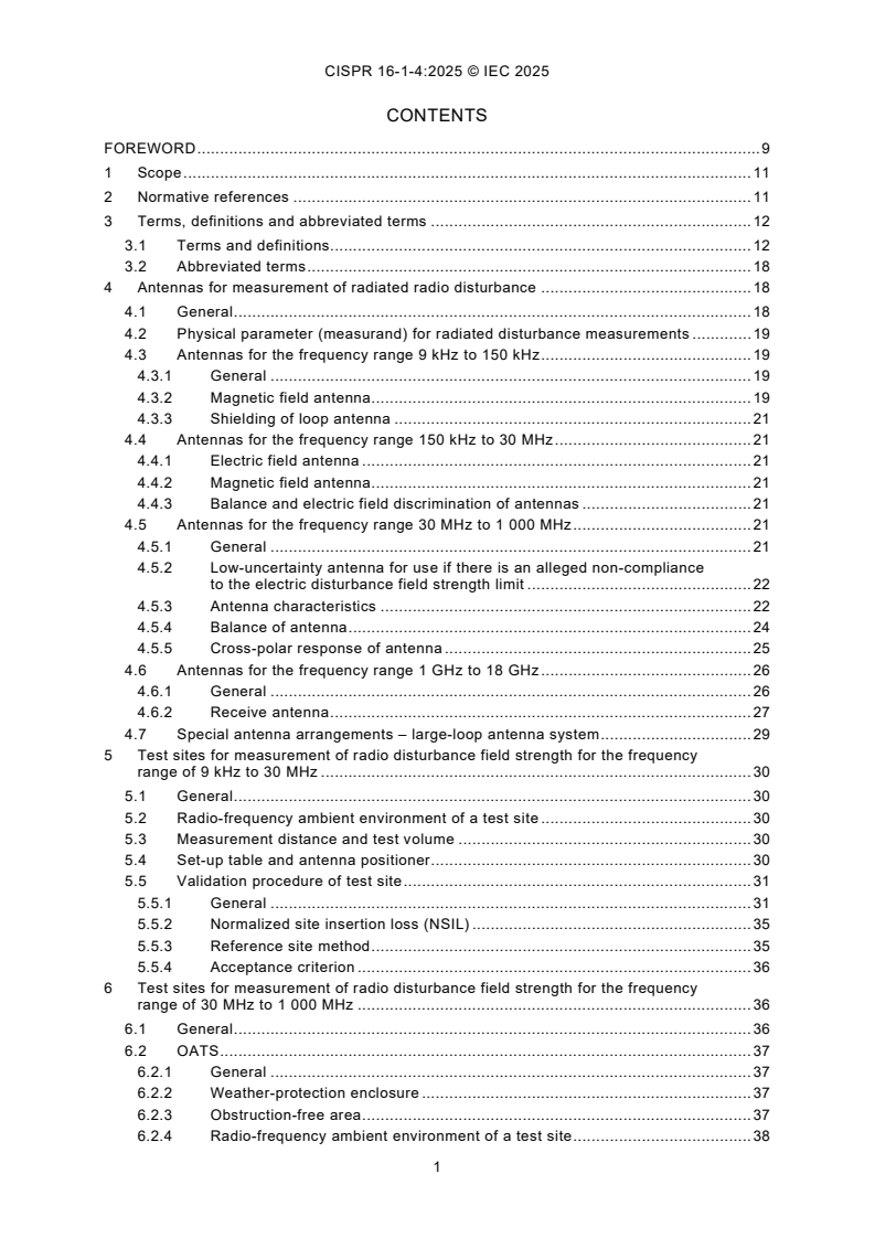
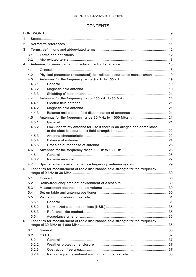
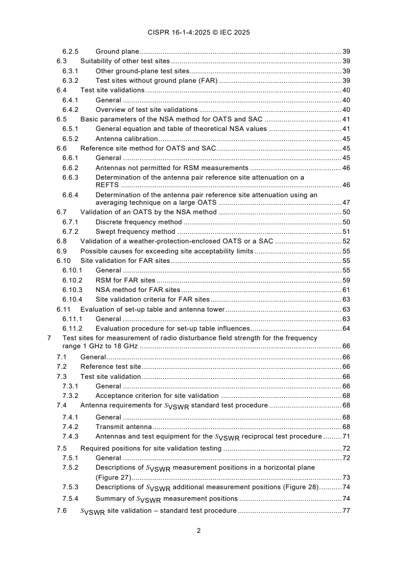
CONTENTS
FOREWORD . 9
1 Scope . 11
2 Normative references . 11
3 Terms, definitions and abbreviated terms . 12
3.1 Terms and definitions. 12
3.2 Abbreviated terms . 18
4 Antennas for measurement of radiated radio disturbance . 18
4.1 General . 18
4.2 Physical parameter (measurand) for radiated disturbance measurements . 19
4.3 Antennas for the frequency range 9 kHz to 150 kHz . 19
4.3.1 General . 19
4.3.2 Magnetic field antenna. 19
4.3.3 Shielding of loop antenna . 21
4.4 Antennas for the frequency range 150 kHz to 30 MHz . 21
4.4.1 Electric field antenna . 21
4.4.2 Magnetic field antenna. 21
4.4.3 Balance and electric field discrimination of antennas . 21
4.5 Antennas for the frequency range 30 MHz to 1 000 MHz . 21
4.5.1 General . 21
4.5.2 Low-uncertainty antenna for use if there is an alleged non-compliance
to the electric disturbance field strength limit . 22
4.5.3 Antenna characteristics . 22
4.5.4 Balance of antenna . 24
4.5.5 Cross-polar response of antenna . 25
4.6 Antennas for the frequency range 1 GHz to 18 GHz . 26
4.6.1 General . 26
4.6.2 Receive antenna . 27
4.7 Special antenna arrangements – large-loop antenna system . 29
5 Test sites for measurement of radio disturbance field strength for the frequency
range of 9 kHz to 30 MHz . 30
5.1 General . 30
5.2 Radio-frequency ambient environment of a test site . 30
5.3 Measurement distance and test volume . 30
5.4 Set-up table and antenna positioner . 30
5.5 Validation procedure of test site . 31
5.5.1 General . 31
5.5.2 Normalized site insertion loss (NSIL) . 35
5.5.3 Reference site method . 35
5.5.4 Acceptance criterion . 36
6 Test sites for measurement of radio disturbance field strength for the frequency
range of 30 MHz to 1 000 MHz . 36
6.1 General . 36
6.2 OATS . 37
6.2.1 General . 37
6.2.2 Weather-protection enclosure . 37
6.2.3 Obstruction-free area . 37
6.2.4 Radio-frequency ambient environment of a test site . 38
6.2.5 Ground plane . 39
6.3 Suitability of other test sites . 39
6.3.1 Other ground-plane test sites . 39
6.3.2 Test sites without ground plane (FAR) . 39
6.4 Test site validations . 40
6.4.1 General . 40
6.4.2 Overview of test site validations . 40
6.5 Basic parameters of the NSA method for OATS and SAC . 41
6.5.1 General equation and table of theoretical NSA values . 41
6.5.2 Antenna calibration . 45
6.6 Reference site method for OATS and SAC . 45
6.6.1 General . 45
6.6.2 Antennas not permitted for RSM measurements . 46
6.6.3 Determination of the antenna pair reference site attenuation on a
REFTS . 46
6.6.4 Determination of the antenna pair reference site attenuation using an
averaging technique on a large OATS . 47
6.7 Validation of an OATS by the NSA method . 50
6.7.1 Discrete frequency method . 50
6.7.2 Swept frequency method . 51
6.8 Validation of a weather-protection-enclosed OATS or a SAC . 52
6.9 Possible causes for exceeding site acceptability limits . 55
6.10 Site validation for FAR sites . 55
6.10.1 General . 55
6.10.2 RSM for FAR sites . 59
6.10.3 NSA method for FAR sites . 61
6.10.4 Site validation criteria for FAR sites . 63
6.11 Evaluation of set-up table and antenna tower . 63
6.11.1 General . 63
6.11.2 Evaluation procedure for set-up table influences. 64
7 Test sites for measurement of radio disturbance field strength for the frequency
range 1 GHz to 18 GHz . 66
7.1 General . 66
7.2 Reference test site . 66
7.3 Test site validation . 66
7.3.1 General . 66
7.3.2 Acceptance criterion for site validation . 68
7.4 Antenna requirements for S standard test procedure . 68
VSWR
7.4.1 General . 68
7.4.2 Transmit antenna . 68
7.4.3 Antennas and test equipment for the S reciprocal test procedure . 71
VSWR
7.5 Required positions for site validation testing . 72
7.5.1 General . 72
7.5.2 Descriptions of S measurement positions in a horizontal plane
VSWR
(Figure 27). 73
7.5.3 Descriptions of S additional measurement positions (Figure 28) . 74
VSWR
7.5.4 Summary of S measurement positions . 74
VSWR
7.6 S site validation – standard test procedure . 77
VSWR
7.7 S site validation – reciprocal test procedure using an isotropic field
VSWR
probe . 78
7.8 S conditional measurement position requirements . 79
VSWR
7.9 S site validation test report . 80
VSWR
7.10 Limitations of the S site validation method . 81
VSWR
7.11 Alternative test sites . 81
8 Cable termination devices used in radiated emission testing . 81
8.1 Common-mode absorption devices . 81
8.1.1 General . 81
8.1.2 CMAD S-parameter measurements . 82
8.1.3 CMAD test jig . 82
8.1.4 Measurement method using the TRL calibration . 83
8.1.5 Specification of ferrite clamp-type CMAD . 85
8.1.6 CMAD performance (degradation) check using spectrum analyzer and
tracking generator . 86
8.2 VHF-LISN cable termination devices . 88
8.2.1 General . 88
8.2.2 Balanced VHF-LISN . 89
8.2.3 Unbalanced VHF-LISN . 90
8.2.4 Measurement of the VHF-LISN impedance . 92
9 Reverberating chamber for total radiated power measurement . 98
10 TEM waveguides for radiated disturbance measurements . 98
Annex A (normative) Parameters of antennas . 99
A.1 General . 99
A.2 Preferred antennas . 99
A.2.1 General . 99
A.2.2 Calculable antenna . 99
A.2.3 Low-uncertainty antennas . 100
A.3 Simple dipole antennas . 101
A.3.1 General . 101
A.3.2 Tuned dipole. 101
A.3.3 Shortened dipole . 101
A.4 Broadband antenna parameters . 103
A.4.1 General . 103
A.4.2 Antenna type . 103
A.4.3 Specification of the antenna . 103
A.4.4 Antenna calibration . 104
A.4.5 Antenna user information . 104
Annex B (normative) Large-loop antenna system for magnetic field induced-current
measurements in the frequency range of 9 kHz to 30 MHz . 106
B.1 General . 106
B.2 Construction of an LLAS . 106
B.3 Construction of a large-loop antenna (LLA) . 106
B.4 Validation of an LLAS . 111
B.5 Construction of the LLAS verification dipole antenna . 113
B.6 Conversion factors . 114
B.6.1 General . 114
B.6.2 Current conversion factors for an LLAS with non-standard diameter . 115
B.6.3 Conversion of LLAS measured current to magnetic field strength . 116
B.7 Examples . 118
Annex C (normative) Construction details for open area test sites in the frequency
range of 30 MHz to 1 000 MHz (see Clause 6) . 119
C.1 General . 119
C.2 Ground plane construction . 119
C.2.1 Material . 119
C.2.2 Roughness . 119
C.3 Services to EUT . 120
C.4 Weather-protection enclosure construction . 120
C.4.1 Materials and fasteners . 120
C.4.2 Internal arrangements . 121
C.4.3 Size . 121
C.4.4 Uniformity with time and weather . 121
C.5 Turntable and set-up table . 121
C.6 Receive antenna mast installation . 122
Annex D (informative) Basis for the ±4 dB site acceptability criterion (see Clause 6) . 123
D.1 General . 123
D.2 Error analysis . 123
Annex E (informative) Examples of uncertainty budgets for site validation of a COMTS
using RSM with a calibrated antenna pair (see 6.6) . 125
E.1 Quantities to be considered for antenna pair reference site attenuation
calibration using the averaging technique . 125
E.2 Quantities to be considered for antenna pair reference site attenuation
calibration using a REFTS . 126
E.3 Quantities to be considered for COMTS validation using an antenna pair
reference site attenuation . 126
Annex F (informative) Definition of uncertainty in cross-polar response measurement . 128
F.1 General . 128
F.2 Example uncertainty estimate . 131
F.3 Rationale for the estimates of input quantities in Table F.1 and Table F.3 . 132
F.4 Measurement of XPR below 100 MHz at an OATS . 134
Annex G (informative) Measurement uncertainties of COMTS validation results in the
frequency range 9 kHz to 30 MHz . 135
G.1 Quantities to be considered for COMTS validation using the NSIL method . 135
G.2 Quantities to be considered for COMTS validation using the RSM method . 137
Annex H (normative) Derivation of NSIL values in the frequency range 9 kHz to
30 MHz . 140
H.1 General . 140
H.2 Magnetic field antenna factor . 141
H.3 Site insertion loss . 142
H.4 Normalized site insertion loss . 144
H.5 NSIL tables . 147
Annex I (informative) Recommendations for the design of test sites in the frequency
range 9 kHz to 30 MHz . 152
I.1 General . 152
I.2 Dimensions and quality of the ground plane . 152
I.3 Obstruction free area . 153
I.4 Resonance-free area . 153
Annex J (informative) Accuracy of NSIL values in the frequency range of 9 kHz to
30 MHz . 155
J.1 General . 155
J.2 Cross-check of NEC with analytic formulas . 155
J.3 Recommended NEC versions . 156
J.4 Instabilities at the lower frequency end . 157
J.5 Extrapolation methods to solve instabilities . 157
J.6 Reducing the number of segments to solve instabilities . 158
Annex K (informative) Example calculation for 10 m SAC sites that do not fulfil the
±4 dB criterion within 9 kHz to 30 MHz . 159
Annex L (normative) Calibration of the sum of magnetic field antenna factors in the
frequency range of 9 kHz to 30 MHz . 162
L.1 General . 162
L.2 Calibration procedure. 162
L.3 Measurement uncertainties . 163
Bibliography . 165
Figure 1 – Example of size-compliant loop antenna . 20
Figure 2 – Schematic of radiation from EUT reaching an LPDA antenna directly and via
ground reflection at a 3 m site, showing the beamwidth half-angle, ϕ,
at the reflected ray . 24
Figure 3 – RX antenna E-plane radiation pattern example, with limit area shaded for 3
m distance and 2 m EUT width . 28
Figure 4 – Determination of maximum useable EUT width using half-power beamwidth . 29
Figure 5 – General arrangement of the three measurement orientations H , H and H ,
x y z
where d is the measurement distance and h is the height of the reference point . 32
Figure 6 – Antenna positions (top view) . 33
Figure 7 – Antenna positions (3D view) . 34
Figure 8 – Test set-up for V with power amplifier and attenuator . 35
DIRECT
Figure 9 – Obstruction-free area of a test site with a turntable . 38
Figure 10 – Obstruction-free area with stationary EUT . 38
Figure 11 – Test point locations for 3 m and 10 m test distances . 47
Figure 12 – Paired test point locations for all test distances . 49
Figure 13 – Example of paired test point selection for a test distance of 10 m . 49
Figure 14 – Illustration of an investigation of influence of antenna mast on A . 50
APR
Figure 15 – Typical antenna positions for a weather-protected OATS or a SAC –
vertical polarization validation measurements . 53
Figure 16 – Typical antenna positions for a weather-protected OATS or a SAC –
horizontal polarization validation measurements . 53
Figure 17 – Typical antenna positions for a weather-protected OATS or a SAC –
vertical polarization validation measurements for a smaller EUT . 54
Figure 18 – Typical antenna positions for a weather-protected OATS or a SAC –
horizontal polarization validation measurements for a smaller EUT . 54
Figure 19 – Measurement positions for FAR site validation . 57
Figure 20 – Example of one measurement position and antenna tilt for FAR site
validation . 58
Figure 21 – Typical quasi free-space test site reference SA measurement set-up . 60
Figure 22 – Theoretical free-space NSA as a function of frequency for different
measurement distances [see Equation (18)]. 63
Figure 23 – Position of the antenna relative to the edge above a rectangle set-up table
(top view) . 66
Figure 24 – Antenna position above the set-up table (side view) . 66
Figure 25 – Transmit antenna E-plane radiation pattern example (this example is for
informative purposes only) . 69
Figure 26 – Transmit antenna H-plane radiation pattern (this example is for informative
purposes only) . 71
Figure 27 – S measurement positions in a horizontal plane (see 7.5.2 for
VSWR
description) . 72
Figure 28 – S positions (height requirements) . 74
VSWR
Figure 29 – S conditional measurement position requirements . 80
VSWR
Figure 30 – Definition of the reference planes inside the test jig . 83
Figure 31 – The four configurations for the TRL calibration . 85
Figure 32 – Limits for the magnitude of S , measured according to the provisions of
8.1.1 to 8.1.3 . 86
Figure 33 – Example of a 50 Ω adaptor construction in the vertical flange of the jig . 87
Figure 34 – Example of a matching adaptor with balun or transformer . 87
Figure 35 – Example of a matching adaptor with resistive matching network . 88
Figure 36 – Example circuit diagram of a balanced VHF-LISN . 90
Figure 37 – Example circuit diagram of an unbalanced VHF-LISN . 91
Figure 38 – Terminal-to-reference ground impedances of the VHF-LISN at the EUT
mains port . 93
Figure 39 – Example VHF-LISN impedance measurement set-up geometry . 95
Figure 40 – Example IMA . 96
Figure 41 – Connection between the IMA and the VHF-LISN . 97
Figure A.1 – Short dipole antenna factors for R = 50 Ω . 102
L
Figure B.1 – The LLAS, consisting of three mutually perpendicular large-loop antennas . 108
Figure B.2 – An LLA containing two opposite slits, positioned symmetrically with
respect to the current probe C . 109
Figure B.3 – Construction of an LLA slit . 109
Figure B.4 – Example of an LLA slit construction using a strap of printed circuit board
to obtain a rigid construction . 110
Figure B.5 – Construction of the metal box containing the current probe . 110
Figure B.6 – Example showing the routing of several cables from an EUT to minimize
capacitive coupling from the leads to the LLAS . 111
Figure B.7 – The eight positions of the LLAS verification dipole during validation
of an LLA . 112
Figure B.8 – Reference validation factors for loops of 2 m, 3 m, and 4 m diameters . 112
Figure B.9 – Construction of the LLAS verification dipole antenna . 114
Figure B.10 – Sensitivity S of an LLA with diameter D relative to an LLA with 2 m
D
diameter . 116
Figure B.11 – Conversion factor C [for conversion into dB(μA/m)] for three standard
dA
measurement distances d . 117
Figure C.1 – The Rayleigh criterion for roughness in the ground plane . 120
Figure H.1 – Investigation of wire radius, normalized to 0,001 m . 144
Figure H.2 – Investigation of feed point location (not to scale) . 145
Figure H.3 – Variation of NSIL values for various set-ups, for a distance of 3 m, h = 1,3 . 147
Figure H.4 – Specification of feed point location for tabular values (not to scale) . 148
Figure H.5 – Calculation examples, loop diameter 60 cm, feed point location per
Figure H.4 . 150
Figure I.1 – Recommended minimum dimensions of the ground plane (top view) . 152
Figure I.2 – Recommended obstruction free area (top view) . 153
Figure J.1 – Comparison of NSIL values by analytic formulas and computer simulation . 156
Figure K.1 – Example site validation result . 160
Figure K.2 – U calculated from site validation result . 161
lab
Figure K.3 – Frequency-dependent correction factor . 161
Figure L.1 – Antenna arrangement for the sum of antenna factors method . 163
Table 1 – Maximum frequency step size . 32
Table 2 – Acceptance criterion . 36
Table 3 – Site validation methods applicable for OATS, OATS-based, SAC, and FAR
site types . 40
Table 4 – Theoretical normalized site attenuation, A – recommended geometries for
N
a
broadband antennas . 43
Table 5 – Example template for A data sets . 46
APR
Table 6 – RSM frequency steps . 46
Table 7 – Maximum dimensions of test volume versus test distance . 55
Table 8 – Frequency ranges and step sizes for FAR site validation . 57
Table 9 – S measurement position designations . 75
VSWR
Table 10 – S reporting requirements . 80
VSWR
Table 11 – Specifications for the EUT mains port of the balanced VHF-LISN . 89
Table 12 – Specifications for the EUT mains port of the unbalanced VHF-LISN . 91
Table B.1 – Reference validation factors of Figure B.8 for loops of 2 m, 3 m, and 4 m
diameters . 113
Table B.2 – Sensitivity S of an LLA with diameter D relative to an LLA with 2 m
D
diameter (Figure B.10) . 115
Table B.3 – Magnetic field strength conversion factor C for three measurement
dA
distances (Figure B.11) . 118
Table C.1 – Maximum roughness for 3 m, 10 m and 30 m measurement distances . 120
Table D.1 – Error budget . 124
Table E.1 – Antenna pair reference site attenuation calibration using the large-OATS
averaging technique . 125
Table E.2 – Antenna pair reference site attenuation calibration using REFTS . 126
Table E.3 – COMTS validation using an antenna pair reference site attenuation . 127
Table F.1 – Example uncertainty estimate for XPR measurement in a FAR and
assumed a = 22 dB, a = 34 dB . 132
xpT xpR
Table F.2 – Uncertainties depending on other values of A (other assumptions as in
xpT
Table F.1) . 134
Table F.3 – Example uncertainty estimate for XPR measurement at an OATS and
assumed a = 22 dB, a = 34 dB . 134
xpT xpR
Table G.1 – Example measurement uncertainty budget for COMTS validation using the
NSIL method . 135
Table G.2 – Example measurement uncertainty budget for COMTS validation using the
RSM method . 138
Table H.1 – Calculation examples (loop diameter 60 cm, d = 3 m, h = 1,3 m) . 150
Table H.2 – Calculation examples (loop diameter 60 cm, d = 5 m, h = 1,3 m) . 150
Table H.3 – Calculation examples (loop diameter 60 cm, d = 10 m, h = 1,3 m) . 151
Table I.1 – Skin depth for some practical materials at 9 kHz . 153
Table J.1 – Recommended NEC implementations . 157
Table J.2 – Observed instabilities . 157
Table K.1 – Measurement uncertainty of radiated disturbance results from 9 kHz to
30 MHz . 159
Table K.2 – Influence of δA on U . 159
i lab
Table L.1 – Example of an uncertainty budget for sum of antenna factors method . 163
INTERNATIONAL ELECTROTECHNICAL COMMISSION
INTERNATIONAL SPECIAL COMMITTEE ON RADIO INTERFERENCE
____________
Specification for radio disturbance and
immunity measuring apparatus and methods -
Part 1-4: Radio disturbance and immunity measuring apparatus -
Antennas and test sites for radiated disturbance measurements
FOREWORD
1) The International Electrotechnical Commission (IEC) is a worldwide organization for standardization comprising
all national electrotechnical committees (IEC National Committees). The object of IEC is to promote international
co-operation on all questions concerning standardization in the electrical and electronic fields. To this end and
in addition to other activities, IEC publishes International Standards, Technical Specifications, Technical Reports,
Publicly Available Specifications (PAS) and Guides (hereafter referred to as "IEC Publication(s)"). Their
preparation is entrusted to technical committees; any IEC National Committee interested in the subject dealt with
may participate in this preparatory work. International, governmental and non-governmental organizations liaising
with the IEC also participate in this preparation. IEC collaborates closely with the International Organization for
Standardization (ISO) in accordance with conditions determined by agreement between the two organizations.
2) The formal decisions or agreements of IEC on technical matters express, as nearly as possible, an international
consensus of opinion on the relevant subjects since each technical committee has representation from all
interested IEC National Committees.
3) IEC Publications have the form of recommendations for international use and are accepted by IEC National
Committees in that sense. While all reasonable efforts are made to ensure that the technical content of IEC
Publications is accurate, IEC cannot be held responsible for the way in which they are used or for any
misinterpretation by any end user.
4) In order to promote international uniformity, IEC National Committees undertake to apply IEC Publications
transparently to the maximum extent possible in their national and regional publications. Any divergence between
any IEC Publication and the corresponding national or regional publication shall be clearly indicated in the latter.
5) IEC itself does not provide any attestation of conformity. Independent certification bodies provide conformity
assessment services and, in some areas, access to IEC marks of conformity. IEC is not responsible for any
services carried out by independent certification bodies.
6) All users should ensure that they have the latest edition of this publication.
7) No liability shall attach to IEC or its directors, employees, servants or agents including individual experts and
members of its technical committees and IEC National Committees for any personal injury, property damage or
other damage of any nature whatsoever, whether direct or indirect, or for costs (including legal fees) and
expenses arising out of the publication, use of, or reliance upon, this IEC Publication or any other I
...
CISPR 16-1-4 ®
Edition 5.0 2025-10
INTERNATIONAL
STANDARD
REDLINE VERSION
INTERNATIONAL SPECIAL COMMITTEE ON RADIO INTERFERENCE
Specification for radio disturbance and immunity measuring apparatus and
methods -
Part 1-4: Radio disturbance and immunity measuring apparatus - Antennas and
test sites for radiated disturbance measurements
ICS 33.100.10; 33.100.20 ISBN 978-2-8327-0762-3
All rights reserved. Unless otherwise specified, no part of this publication may be reproduced or utilized in any form or
by any means, electronic or mechanical, including photocopying and microfilm, without permission in writing from either
IEC or IEC's member National Committee in the country of the requester. If you have any questions about IEC copyright
or have an enquiry about obtaining additional rights to this publication, please contact the address below or your local
IEC member National Committee for further information.
IEC Secretariat Tel.: +41 22 919 02 11
3, rue de Varembé info@iec.ch
CH-1211 Geneva 20 www.iec.ch
Switzerland
About the IEC
The International Electrotechnical Commission (IEC) is the leading global organization that prepares and publishes
International Standards for all electrical, electronic and related technologies.
About IEC publications
The technical content of IEC publications is kept under constant review by the IEC. Please make sure that you have the
latest edition, a corrigendum or an amendment might have been published.
IEC publications search - IEC Products & Services Portal - products.iec.ch
webstore.iec.ch/advsearchform Discover our powerful search engine and read freely all the
The advanced search enables to find IEC publications by a publications previews, graphical symbols and the glossary.
variety of criteria (reference number, text, technical With a subscription you will always have access to up to date
committee, …). It also gives information on projects, content tailored to your needs.
replaced and withdrawn publications.
Electropedia - www.electropedia.org
The world's leading online dictionary on electrotechnology,
IEC Just Published - webstore.iec.ch/justpublished
Stay up to date on all new IEC publications. Just Published containing more than 22 500 terminological entries in English
details all new publications released. Available online and and French, with equivalent terms in 25 additional languages.
once a month by email. Also known as the International Electrotechnical Vocabulary
(IEV) online.
IEC Customer Service Centre - webstore.iec.ch/csc
If you wish to give us your feedback on this publication or
need further assistance, please contact the Customer
Service Centre: sales@iec.ch.
CONTENTS
FOREWORD . 9
1 Scope . 1
2 Normative references . 11
3 Terms, definitions and abbreviated terms . 12
3.1 Terms and definitions. 12
3.2 Abbreviated terms . 18
4 Antennas for measurement of radiated radio disturbance . 19
4.1 General . 19
4.2 Physical parameter (measurand) for radiated disturbance measurements . 19
4.3 Antennas for the frequency range 9 kHz to 150 kHz . 19
4.3.1 General . 19
4.3.2 Magnetic field antenna. 19
4.3.3 Shielding of loop antenna . 21
4.4 Antennas for the frequency range 150 kHz to 30 MHz . 21
4.4.1 Electric field antenna . 21
4.4.2 Magnetic field antenna. 21
4.4.3 Balance and electric field discrimination of antennas . 21
4.5 Antennas for the frequency range 30 MHz to 1 000 MHz . 22
4.5.1 General . 22
4.5.2 Low-uncertainty antenna for use if there is an alleged non-compliance
to the electric disturbance field strength limit . 22
4.5.3 Antenna characteristics . 22
4.5.4 Balance of antenna . 24
4.5.5 Cross-polar response of antenna . 25
4.6 Antennas for the frequency range 1 GHz to 18 GHz . 26
4.6.1 General . 26
4.6.2 Receive antenna . 27
4.7 Special antenna arrangements – large-loop antenna system . 29
5 Test sites for measurement of radio disturbance field strength for the frequency
range of 9 kHz to 30 MHz . 30
5.1 General . 30
5.2 Radio-frequency ambient environment of a test site . 30
5.3 Measurement distance and test volume . 30
5.4 Set-up table and antenna positioner . 30
5.5 Validation procedure of test site . 31
5.5.1 General . 31
5.5.2 Normalized site insertion loss (NSIL) . 35
5.5.3 Reference site method . 35
5.5.4 Acceptance criterion . 36
6 Test sites for measurement of radio disturbance field strength for the frequency
range of 30 MHz to 1 000 MHz . 36
6.1 General . 36
6.2 OATS . 37
6.2.1 General . 37
6.2.2 Weather-protection enclosure . 37
6.2.3 Obstruction-free area . 37
6.2.4 Radio-frequency ambient environment of a test site . 38
6.2.5 Ground plane . 39
6.3 Suitability of other test sites . 39
6.3.1 Other ground-plane test sites . 39
6.3.2 Test sites without ground plane (FAR) . 39
6.4 Test site validations . 40
6.4.1 General . 40
6.4.2 Overview of test site validations . 40
6.5 Basic parameters of the NSA method for OATS and SAC . 41
6.5.1 General equation and table of theoretical NSA values . 41
6.5.2 Antenna calibration . 45
6.6 Reference site method for OATS and SAC . 45
6.6.1 General . 45
6.6.2 Antennas not permitted for RSM measurements . 45
6.6.3 Determination of the antenna pair reference site attenuation on a
REFTS . 46
6.6.4 Determination of the antenna pair reference site attenuation using an
averaging technique on a large OATS . 47
6.7 Validation of an OATS by the NSA method . 50
6.7.1 Discrete frequency method . 50
6.7.2 Swept frequency method . 51
6.8 Validation of a weather-protection-enclosed OATS or a SAC . 52
6.9 Possible causes for exceeding site acceptability limits . 55
6.10 Site validation for FAR sites . 55
6.10.1 General . 55
6.10.2 RSM for FAR sites . 59
6.10.3 NSA method for FAR sites . 61
6.10.4 Site validation criteria for FAR sites . 63
6.11 Evaluation of set-up table and antenna tower . 63
6.11.1 General . 63
6.11.2 Evaluation procedure for set-up table influences. 64
7 Test sites for measurement of radio disturbance field strength for the frequency
range 1 GHz to 18 GHz . 66
7.1 General . 66
7.2 Reference test site . 66
7.3 Test site validation . 66
7.3.1 General . 66
7.3.2 Acceptance criterion for site validation . 68
7.4 Antenna requirements for S standard test procedure . 68
VSWR
7.4.1 General . 68
7.4.2 Transmit antenna . 68
7.4.3 Antennas and test equipment for the S reciprocal test procedure . 71
VSWR
7.5 Required positions for site validation testing . 72
7.5.1 General . 72
7.5.2 Descriptions of S measurement positions in a horizontal plane
VSWR
(Figure 27). 73
7.5.3 Descriptions of S additional measurement positions (Figure 28) . 74
VSWR
7.5.4 Summary of S measurement positions . 74
VSWR
7.6 S site validation – standard test procedure . 77
VSWR
7.7 S site validation – reciprocal test procedure using an isotropic field
VSWR
probe . 78
7.8 S conditional measurement position requirements . 79
VSWR
7.9 S site validation test report . 80
VSWR
7.10 Limitations of the S site validation method . 81
VSWR
7.11 Alternative test sites . 81
8 Cable termination devices used in radiated emission testing . 81
8.1 Common-mode absorption devices . 81
8.1.1 General . 81
8.1.2 CMAD S-parameter measurements . 82
8.1.3 CMAD test jig . 82
8.1.4 Measurement method using the TRL calibration . 83
8.1.5 Specification of ferrite clamp-type CMAD . 85
8.1.6 CMAD performance (degradation) check using spectrum analyzer and
tracking generator . 86
8.2 VHF-LISN cable termination devices . 88
8.2.1 General . 88
8.2.2 Balanced VHF-LISN . 89
8.2.3 Unbalanced VHF-LISN . 90
8.2.4 Measurement of the VHF-LISN impedance . 92
9 Reverberating chamber for total radiated power measurement . 98
10 TEM waveguides for radiated disturbance measurements . 98
Annex A (normative) Parameters of antennas . 99
A.1 General . 99
A.2 Preferred antennas . 99
A.2.1 General . 99
A.2.2 Calculable antenna . 99
A.2.3 Low-uncertainty antennas . 100
A.3 Simple dipole antennas . 101
A.3.1 General . 101
A.3.2 Tuned dipole. 101
A.3.3 Shortened dipole . 101
A.4 Broadband antenna parameters . 103
A.4.1 General . 103
A.4.2 Antenna type . 103
A.4.3 Specification of the antenna . 103
A.4.4 Antenna calibration . 104
A.4.5 Antenna user information . 104
Annex B (XXX) (Void) .
Annex B (normative) Large-loop antenna system for magnetic field induced-current
measurements in the frequency range of 9 kHz to 30 MHz . 107
B.1 General . 107
B.2 Construction of an LLAS . 107
B.3 Construction of a large-loop antenna (LLA) . 107
B.4 Validation of an LLAS . 112
B.5 Construction of the LLAS verification dipole antenna . 114
B.6 Conversion factors . 115
B.6.1 General . 115
B.6.2 Current conversion factors for an LLAS with non-standard diameter . 116
B.6.3 Conversion of LLAS measured current to magnetic field strength . 117
B.7 Examples . 119
Annex C (normative) Construction details for open area test sites in the frequency
range of 30 MHz to 1 000 MHz (see Clause 6) . 120
C.1 General . 120
C.2 Ground plane construction . 120
C.2.1 Material . 120
C.2.2 Roughness . 120
C.3 Services to EUT . 121
C.4 Weather-protection enclosure construction . 121
C.4.1 Materials and fasteners . 121
C.4.2 Internal arrangements . 122
C.4.3 Size . 122
C.4.4 Uniformity with time and weather . 122
C.5 Turntable and set-up table . 122
C.6 Receive antenna mast installation . 123
Annex D (informative) Basis for the ±4 dB site acceptability criterion (see Clause 6) . 124
D.1 General . 124
D.2 Error analysis . 124
Annex E (XXX) (Void) .
Annex E (informative) Examples of uncertainty budgets for site validation of a COMTS
using RSM with a calibrated antenna pair (see 6.6) . 127
E.1 Quantities to be considered for antenna pair reference site attenuation
calibration using the averaging technique . 127
E.2 Quantities to be considered for antenna pair reference site attenuation
calibration using a REFTS . 128
E.3 Quantities to be considered for COMTS validation using an antenna pair
reference site attenuation . 128
Annex F (informative) Definition of uncertainty in cross-polar response measurement . 130
F.1 General . 130
F.2 Example uncertainty estimate . 133
F.3 Rationale for the estimates of input quantities in Table F.1 and Table F.3 . 134
F.4 Measurement of XPR below 100 MHz at an OATS . 136
Annex G (informative) Measurement uncertainties of COMTS validation results in the
frequency range 9 kHz to 30 MHz . 137
G.1 Quantities to be considered for COMTS validation using the NSIL method . 137
G.2 Quantities to be considered for COMTS validation using the RSM method . 139
Annex H (normative) Derivation of NSIL values in the frequency range 9 kHz to
30 MHz . 142
H.1 General . 142
H.2 Magnetic field antenna factor . 143
H.3 Site insertion loss . 144
H.4 Normalized site insertion loss . 146
H.5 NSIL tables . 149
Annex I (informative) Recommendations for the design of test sites in the frequency
range 9 kHz to 30 MHz . 154
I.1 General . 154
I.2 Dimensions and quality of the ground plane . 154
I.3 Obstruction free area . 155
I.4 Resonance-free area . 155
Annex J (informative) Accuracy of NSIL values in the frequency range of 9 kHz to
30 MHz . 157
J.1 General . 157
J.2 Cross-check of NEC with analytic formulas . 157
J.3 Recommended NEC versions . 158
J.4 Instabilities at the lower frequency end . 159
J.5 Extrapolation methods to solve instabilities . 159
J.6 Reducing the number of segments to solve instabilities . 160
Annex K (informative) Example calculation for 10 m SAC sites that do not fulfil the
±4 dB criterion within 9 kHz to 30 MHz . 161
Annex L (normative) Calibration of the sum of magnetic field antenna factors in the
frequency range of 9 kHz to 30 MHz . 164
L.1 General . 164
L.2 Calibration procedure. 164
L.3 Measurement uncertainties . 165
Bibliography . 167
Figure 1 – Example of size-compliant loop antenna . 20
Figure 2 – Schematic of radiation from EUT reaching an LPDA antenna directly and via
ground reflection at a 3 m site, showing the beamwidth half-angle, ϕ,
at the reflected ray . 24
Figure 3 – RX antenna E-plane radiation pattern example, with limit area shaded for 3
m distance and 2 m EUT width . 28
Figure 4 – Determination of maximum useable EUT width using half-power beamwidth . 29
Figure 5 – General arrangement of the three measurement orientations H , H and H ,
x y z
where d is the measurement distance and h is the height of the reference point . 32
Figure 6 – Antenna positions (top view) . 33
Figure 7 – Antenna positions (3D view) . 34
Figure 8 – Test set-up for V with power amplifier and attenuator . 35
DIRECT
Figure 9 – Obstruction-free area of a test site with a turntable . 38
Figure 10 – Obstruction-free area with stationary EUT . 38
Figure 11 – Test point locations for 3 m and 10 m test distances . 47
Figure 12 – Paired test point locations for all test distances . 49
Figure 13 – Example of paired test point selection for a test distance of 10 m . 49
Figure 14 – Illustration of an investigation of influence of antenna mast on A . 50
APR
Figure 15 – Typical antenna positions for a weather-protected OATS or a SAC –
vertical polarization validation measurements . 53
Figure 16 – Typical antenna positions for a weather-protected OATS or a SAC –
horizontal polarization validation measurements . 53
Figure 17 – Typical antenna positions for a weather-protected OATS or a SAC –
vertical polarization validation measurements for a smaller EUT . 54
Figure 18 – Typical antenna positions for a weather-protected OATS or a SAC –
horizontal polarization validation measurements for a smaller EUT . 54
Figure 19 – Measurement positions for FAR site validation . 57
Figure 20 – Example of one measurement position and antenna tilt for FAR site
validation . 58
Figure 21 – Typical quasi free-space test site reference SA measurement set-up . 60
Figure 22 – Theoretical free-space NSA as a function of frequency for different
measurement distances [see Equation (18)]. 63
Figure 23 – Position of the antenna relative to the edge above a rectangle set-up table
(top view) . 66
Figure 24 – Antenna position above the set-up table (side view) . 66
Figure 25 – Transmit antenna E-plane radiation pattern example (this example is for
informative purposes only) . 69
Figure 26 – Transmit antenna H-plane radiation pattern (this example is for informative
purposes only) . 71
Figure 27 – S measurement positions in a horizontal plane (see 7.5.2 for
VSWR
description) . 72
Figure 28 – S positions (height requirements) . 74
VSWR
Figure 29 – S conditional measurement position requirements . 80
VSWR
Figure 30 – Definition of the reference planes inside the test jig . 83
Figure 31 – The four configurations for the TRL calibration . 85
Figure 32 – Limits for the magnitude of S , measured according to the provisions of
8.1.1 to 8.1.3 . 86
Figure 33 – Example of a 50 Ω adaptor construction in the vertical flange of the jig . 87
Figure 34 – Example of a matching adaptor with balun or transformer . 88
Figure 35 – Example of a matching adaptor with resistive matching network . 88
Figure 36 – Example circuit diagram of a balanced VHF-LISN . 90
Figure 37 – Example circuit diagram of an unbalanced VHF-LISN . 91
Figure 38 – Terminal-to-reference ground impedances of the VHF-LISN at the EUT
mains port . 93
Figure 39 – Example VHF-LISN impedance measurement set-up geometry . 95
Figure 40 – Example IMA . 96
Figure 41 – Connection between the IMA and the VHF-LISN . 97
Figure A.1 – Short dipole antenna factors for R = 50 Ω . 102
L
Figure B.1 – The LLAS, consisting of three mutually perpendicular large-loop antennas . 109
Figure B.2 – An LLA containing two opposite slits, positioned symmetrically with
respect to the current probe C . 110
Figure B.3 – Construction of an LLA slit . 110
Figure B.4 – Example of an LLA slit construction using a strap of printed circuit board
to obtain a rigid construction . 111
Figure B.5 – Construction of the metal box containing the current probe . 111
Figure B.6 – Example showing the routing of several cables from an EUT to minimize
capacitive coupling from the leads to the LLAS . 112
Figure B.7 – The eight positions of the LLAS verification dipole during validation
of an LLA . 113
Figure B.8 – Reference validation factors for loops of 2 m, 3 m, and 4 m diameters . 113
Figure B.9 – Construction of the LLAS verification dipole antenna . 115
Figure B.10 – Sensitivity S of an LLA with diameter D relative to an LLA with 2 m
D
diameter . 117
Figure B.11 – Conversion factor C [for conversion into dB(μA/m)] for three standard
dA
measurement distances d . 118
Figure C.1 – The Rayleigh criterion for roughness in the ground plane . 121
Figure H.1 – Investigation of wire radius, normalized to 0,001 m . 146
Figure H.2 – Investigation of feed point location (not to scale) . 147
Figure H.3 – Variation of NSIL values for various set-ups, for a distance of 3 m, h = 1,3 . 149
Figure H.4 – Specification of feed point location for tabular values (not to scale) . 150
Figure H.5 – Calculation examples, loop diameter 60 cm, feed point location per
Figure H.4 . 152
Figure I.1 – Recommended minimum dimensions of the ground plane (top view) . 154
Figure I.2 – Recommended obstruction free area (top view) . 155
Figure J.1 – Comparison of NSIL values by analytic formulas and computer simulation . 158
Figure K.1 – Example site validation result . 162
Figure K.2 – U calculated from site validation result . 163
lab
Figure K.3 – Frequency-dependent correction factor . 163
Figure L.1 – Antenna arrangement for the sum of antenna factors method . 165
Table 1 – Maximum frequency step size . 32
Table 2 – Acceptance criterion . 36
Table 3 – Site validation methods applicable for OATS, OATS-based, SAC, and FAR
site types . 40
Table 4 – Theoretical normalized site attenuation, A – recommended geometries for
N
a
broadband antennas . 43
Table 5 – Example template for A data sets . 46
APR
Table 6 – RSM frequency steps . 46
Table 7 – Maximum dimensions of test volume versus test distance . 55
Table 8 – Frequency ranges and step sizes for FAR site validation . 57
Table 9 – S measurement position designations . 75
VSWR
Table 10 – S reporting requirements . 80
VSWR
Table 11 – Specifications for the EUT mains port of the balanced VHF-LISN . 89
Table 12 – Specifications for the EUT mains port of the unbalanced VHF-LISN . 91
Table B.1 – Reference validation factors of Figure B.8 for loops of 2 m, 3 m, and 4 m
diameters . 114
Table B.2 – Sensitivity S of an LLA with diameter D relative to an LLA with 2 m
D
diameter (Figure B.10) . 116
Table B.3 – Magnetic field strength conversion factor C for three measurement
dA
distances (Figure B.11) . 119
Table C.1 – Maximum roughness for 3 m, 10 m and 30 m measurement distances . 121
Table D.1 – Error budget . 125
Table E.1 – Antenna pair reference site attenuation calibration using the large-OATS
averaging technique . 127
Table E.2 – Antenna pair reference site attenuation calibration using REFTS . 128
Table E.3 – COMTS validation using an antenna pair reference site attenuation . 129
Table F.1 – Example uncertainty estimate for XPR measurement in a FAR and
assumed a = 22 dB, a = 34 dB . 134
xpT xpR
Table F.2 – Uncertainties depending on other values of A (other assumptions as in
xpT
Table F.1) . 136
Table F.3 – Example uncertainty estimate for XPR measurement at an OATS and
assumed a = 22 dB, a = 34 dB . 136
xpT xpR
Table G.1 – Example measurement uncertainty budget for COMTS validation using the
NSIL method . 137
Table G.2 – Example measurement uncertainty budget for COMTS validation using the
RSM method . 140
Table H.1 – Calculation examples (loop diameter 60 cm, d = 3 m, h = 1,3 m) . 152
Table H.2 – Calculation examples (loop diameter 60 cm, d = 5 m, h = 1,3 m) . 152
Table H.3 – Calculation examples (loop diameter 60 cm, d = 10 m, h = 1,3 m) . 153
Table I.1 – Skin depth for some practical materials at 9 kHz . 155
Table J.1 – Recommended NEC implementations . 159
Table J.2 – Observed instabilities . 159
Table K.1 – Measurement uncertainty of radiated disturbance results from 9 kHz to
30 MHz . 161
Table K.2 – Influence of δA on U . 161
i lab
Table L.1 – Example of an uncertainty budget for sum of antenna factors method . 165
INTERNATIONAL ELECTROTECHNICAL COMMISSION
INTERNATIONAL SPECIAL COMMITTEE ON RADIO INTERFERENCE
____________
Specification for radio disturbance and
immunity measuring apparatus and methods -
Part 1-4: Radio disturbance and immunity measuring apparatus -
Antennas and test sites for radiated disturbance measurements
FOREWORD
1) The International Electrotechnical Commission (IEC) is a worldwide organization for standardization comprising
all national electrotechnical committees (IEC National Committees). The object of IEC is to promote international
co-operation on all questions concerning standardization in the electrical and electronic fields. To this end and
in addition to other activities, IEC publishes International Standards, Technical Specifications, Technical Reports,
Publicly Available Specifications (PAS) and Guides (hereafter referred to as "IEC Publication(s)"). Their
preparation is entrusted to technical committees; any IEC National Committee interested in the subject dealt with
may participate in this preparatory work. International, governmental and non-governmental organizations liaising
with the IEC also participate in this preparation. IEC collaborates closely with the International Organization for
Standardization (ISO) in accordance with conditions determined by agreement between the two organizations.
2) The formal decisions or agreements of IEC on technical matters express, as nearly as possible, an international
consensus of opinion on the relevant subjects since each technical committee has representation from all
interested IEC National Committees.
3) IEC Publications have the form of recommendations for international use and are accepted by IEC National
Committees in that sense. While all reasonable efforts are made to ensure that the technical content of IEC
Publications is accurate, IEC cannot be held responsible for the way in which they are used or for any
misinterpretation by any end user.
4) In order to promote international uniformity, IEC National Committees undertake to apply IEC Publications
transparently to the maximum extent possible in their national and regional publications. Any divergence between
any IEC Publication and the corresponding national or regional publication shall be clearly indicated in the latter.
5) IEC itself does not provide any attestation of conformity. Independent certification bodies provide conformity
assessment services and, in some areas, access to IEC marks of conformity. IEC is not responsible for any
services carried out by independent certification bodies.
6) All users should ensure that they have the latest edition of this publication.
7) No liability shall attach to IEC or its directors, employees, servants or agents including individual experts and
...
CISPR 16-1-4 ®
Edition 5.0 2025-10
NORME
INTERNATIONALE
COMITÉ INTERNATIONAL SPÉCIAL DES PERTURBATIONS RADIOÉLECTRIQUES
Spécifications des méthodes et des appareils de mesure des perturbations
radioélectriques et de l'immunité aux perturbations radioélectriques -
Partie 1-4: Appareils de mesure des perturbations radioélectriques et de
l'immunité aux perturbations radioélectriques - Antennes et emplacements
d'essai pour les mesurages des perturbations rayonnées
ICS 33.100.10; 33.100.20 ISBN 978-2-8327-0736-4
Droits de reproduction réservés. Sauf indication contraire, aucune partie de cette publication ne peut être reproduite ni
utilisée sous quelque forme que ce soit et par aucun procédé, électronique ou mécanique, y compris la photocopie et
les microfilms, sans l'accord écrit de l'IEC ou du Comité national de l'IEC du pays du demandeur. Si vous avez des
questions sur le copyright de l'IEC ou si vous désirez obtenir des droits supplémentaires sur cette publication, utilisez
les coordonnées ci-après ou contactez le Comité national de l'IEC de votre pays de résidence.
IEC Secretariat Tel.: +41 22 919 02 11
3, rue de Varembé info@iec.ch
CH-1211 Geneva 20 www.iec.ch
Switzerland
A propos de l'IEC
La Commission Electrotechnique Internationale (IEC) est la première organisation mondiale qui élabore et publie des
Normes internationales pour tout ce qui a trait à l'électricité, à l'électronique et aux technologies apparentées.
A propos des publications IEC
Le contenu technique des publications IEC est constamment revu. Veuillez vous assurer que vous possédez l’édition la
plus récente, un corrigendum ou amendement peut avoir été publié.
Recherche de publications IEC - IEC Products & Services Portal - products.iec.ch
webstore.iec.ch/advsearchform Découvrez notre puissant moteur de recherche et consultez
La recherche avancée permet de trouver des publications gratuitement tous les aperçus des publications, symboles
IEC en utilisant différents critères (numéro de référence, graphiques et le glossaire. Avec un abonnement, vous aurez
texte, comité d’études, …). Elle donne aussi des toujours accès à un contenu à jour adapté à vos besoins.
informations sur les projets et les publications remplacées
ou retirées. Electropedia - www.electropedia.org
Le premier dictionnaire d'électrotechnologie en ligne au
IEC Just Published - webstore.iec.ch/justpublished monde, avec plus de 22 500 articles terminologiques en
Restez informé sur les nouvelles publications IEC. Just anglais et en français, ainsi que les termes équivalents
dans 25 langues additionnelles. Egalement appelé
Published détaille les nouvelles publications parues.
Disponible en ligne et une fois par mois par email. Vocabulaire Electrotechnique International (IEV) en ligne.
Service Clients - webstore.iec.ch/csc
Si vous désirez nous donner des commentaires sur cette
publication ou si vous avez des questions contactez-
nous: sales@iec.ch.
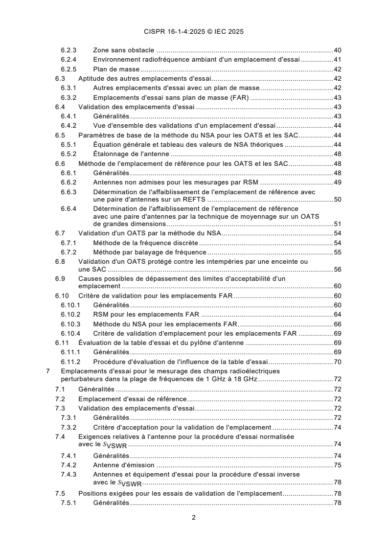
SOMMAIRE
AVANT-PROPOS . 10
1 Domaine d'application . 12
2 Références normatives . 12
3 Termes, définitions et abréviations . 13
3.1 Termes et définitions . 13
3.2 Abréviations . 20
4 Antennes pour le mesurage des perturbations radioélectriques rayonnées . 21
4.1 Généralités . 21
4.2 Paramètre physique (mesurande) pour les mesurages des perturbations
rayonnées . 21
4.3 Antennes pour la plage de fréquences de 9 kHz à 150 kHz . 22
4.3.1 Généralités . 22
4.3.2 Antenne à champ magnétique. 22
4.3.3 Blindage de l'antenne-cadre . 23
4.4 Antennes pour la plage de fréquences de 150 kHz à 30 MHz . 23
4.4.1 Antenne à champ électrique . 23
4.4.2 Antenne à champ magnétique. 24
4.4.3 Symétrisation et discrimination du champ électrique des antennes . 24
4.5 Antennes pour la plage de fréquences de 30 MHz à 1 000 MHz . 24
4.5.1 Généralités . 24
4.5.2 Antenne à faible incertitude pour utilisation en cas de non-conformité
présumée des limites d'intensité du champ électrique . 24
4.5.3 Caractéristiques de l'antenne . 25
4.5.4 Symétrisation de l'antenne . 27
4.5.5 Réponse de polarisation croisée de l'antenne . 29
4.6 Antennes pour la plage de fréquences de 1 GHz à 18 GHz . 30
4.6.1 Généralités . 30
4.6.2 Antenne de réception . 30
4.7 Montages d'antennes particuliers – Système d'antennes-cadres de grand
diamètre . 32
5 Emplacements d'essai pour le mesurage des champs radioélectriques
perturbateurs dans la plage de fréquences de 9 kHz à 30 MHz . 33
5.1 Généralités . 33
5.2 Environnement radiofréquence ambiant d'un emplacement d'essai . 33
5.3 Distance de mesure et volume d'essai . 33
5.4 Table d'essai et positionneur d'antenne . 33
5.5 Procédure de validation de l'emplacement d'essai . 34
5.5.1 Généralités . 34
5.5.2 Perte d'insertion normalisée de l'emplacement (NSIL) . 38
5.5.3 Méthode de l'emplacement de référence . 38
5.5.4 Critère d'acceptation . 39
6 Emplacements d'essai pour le mesurage des champs radioélectriques
perturbateurs dans la plage de fréquences de 30 MHz à 1 000 MHz . 39
6.1 Généralités . 39
6.2 OATS . 40
6.2.1 Généralités . 40
6.2.2 Enceinte de protection contre les intempéries . 40
6.2.3 Zone sans obstacle . 40
6.2.4 Environnement radiofréquence ambiant d'un emplacement d'essai . 41
6.2.5 Plan de masse . 42
6.3 Aptitude des autres emplacements d'essai . 42
6.3.1 Autres emplacements d'essai avec un plan de masse . 42
6.3.2 Emplacements d'essai sans plan de masse (FAR) . 43
6.4 Validation des emplacements d'essai . 43
6.4.1 Généralités . 43
6.4.2 Vue d'ensemble des validations d'un emplacement d'essai . 44
6.5 Paramètres de base de la méthode du NSA pour les OATS et les SAC . 44
6.5.1 Équation générale et tableau des valeurs de NSA théoriques . 44
6.5.2 Étalonnage de l'antenne . 48
6.6 Méthode de l'emplacement de référence pour les OATS et les SAC . 48
6.6.1 Généralités . 48
6.6.2 Antennes non admises pour les mesurages par RSM . 49
6.6.3 Détermination de l'affaiblissement de l'emplacement de référence avec
une paire d'antennes sur un REFTS . 50
6.6.4 Détermination de l'affaiblissement de l'emplacement de référence
avec une paire d'antennes par la technique de moyennage sur un OATS
de grandes dimensions . 51
6.7 Validation d'un OATS par la méthode du NSA . 54
6.7.1 Méthode de la fréquence discrète . 54
6.7.2 Méthode par balayage de fréquence . 55
6.8 Validation d'un OATS protégé contre les intempéries par une enceinte ou
une SAC . 56
6.9 Causes possibles de dépassement des limites d'acceptabilité d'un
emplacement . 60
6.10 Critère de validation pour les emplacements FAR . 60
6.10.1 Généralités . 60
6.10.2 RSM pour les emplacements FAR . 64
6.10.3 Méthode du NSA pour les emplacements FAR . 66
6.10.4 Critère de validation d'emplacement pour les emplacements FAR . 69
6.11 Évaluation de la table d'essai et du pylône d'antenne . 69
6.11.1 Généralités . 69
6.11.2 Procédure d'évaluation de l'influence de la table d'essai . 70
7 Emplacements d'essai pour le mesurage des champs radioélectriques
perturbateurs dans la plage de fréquences de 1 GHz à 18 GHz . 72
7.1 Généralités . 72
7.2 Emplacement d'essai de référence. 72
7.3 Validation des emplacements d'essai . 72
7.3.1 Généralités . 72
7.3.2 Critère d'acceptation pour la validation de l'emplacement . 74
7.4 Exigences relatives à l'antenne pour la procédure d'essai normalisée
avec le S . 74
VSWR
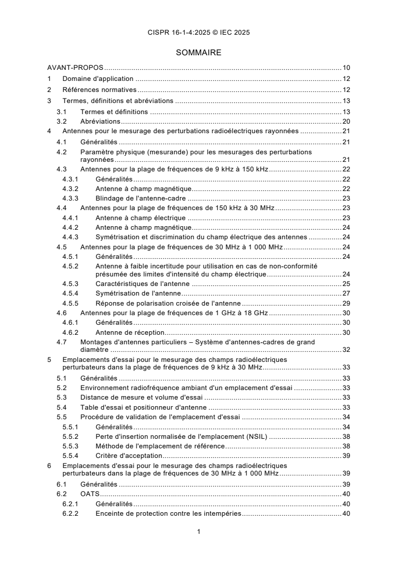
7.4.1 Généralités . 74
7.4.2 Antenne d'émission . 75
7.4.3 Antennes et équipement d'essai pour la procédure d'essai inverse
avec le S . 78
VSWR
7.5 Positions exigées pour les essais de validation de l'emplacement . 78
7.5.1 Généralités . 78
7.5.2 Description des positions de mesure de S dans un plan horizontal
VSWR
(Figure 27). 79
7.5.3 Description des positions de mesure supplémentaires de S
VSWR
(Figure 28). 80
7.5.4 Récapitulatif des positions de mesure de S . 81
VSWR
7.6 Validation de l'emplacement de S – procédure d'essai normalisée . 84
VSWR
7.7 Validation d'emplacement avec le S – procédure d'essai inverse
VSWR
utilisant une sonde de champ isotrope . 85
7.8 Exigences concernant les positions de mesure conditionnelles de S . 86
VSWR
7.9 Rapport d'essai de validation d'emplacement avec le S . 87
VSWR
7.10 Limites de la méthode de validation d'emplacement avec le S . 88
VSWR
7.11 Autres emplacements d'essai . 88
8 Dispositifs de terminaison de câble utilisés pour les essais des émissions
rayonnées . 89
8.1 Dispositifs d'absorption en mode commun . 89
8.1.1 Généralités . 89
8.1.2 Mesurages des paramètres S d'un CMAD . 89
8.1.3 Montage d'essai de CMAD . 89
8.1.4 Méthode de mesure utilisant l'étalonnage TRL . 91
8.1.5 Spécification d'un CMAD du type à pince en ferrite . 93
8.1.6 Vérification de la performance (dégradation) des CMAD en utilisant un
analyseur de spectre et un générateur de poursuite . 95
8.2 Dispositifs de terminaison de câble RISL-VHF . 97
8.2.1 Généralités . 97
8.2.2 RISL-VHF symétrique . 98
8.2.3 RISL-VHF asymétrique . 99
8.2.4 Mesurage de l'impédance du RISL-VHF . 101
9 Chambre de réverbération pour le mesurage de la puissance totale rayonnée . 107
10 Guides d'onde TEM pour les mesurages des perturbations rayonnées. 107
Annexe A (normative) Paramètres des antennes. 108
A.1 Généralités . 108
A.2 Antennes préférentielles . 108
A.2.1 Généralités . 108
A.2.2 Antenne calculable . 108
A.2.3 Antennes à faible incertitude . 109
A.3 Antennes doublets simples . 110
A.3.1 Généralités . 110
A.3.2 Doublet accordé . 110
A.3.3 Doublet raccourci . 111
A.4 Paramètres des antennes à large bande . 113
A.4.1 Généralités . 113
A.4.2 Type d'antenne . 113
A.4.3 Spécification de l'antenne . 113
A.4.4 Étalonnage de l'antenne . 114
A.4.5 Informations pour les utilisateurs de l'antenne . 114
Annexe B (normative) Système d'antennes-cadres de grand diamètre pour les
mesurages du courant induit par un champ magnétique dans la plage de fréquences
de 9 kHz à 30 MHz . 116
B.1 Généralités . 116
B.2 Construction d'un LLAS . 116
B.3 Construction d'une antenne-cadre de grand diamètre (LLA) . 116
B.4 Validation d'une LLAS . 121
B.5 Construction de l'antenne doublet de vérification du LLAS . 123
B.6 Facteurs de conversion . 124
B.6.1 Généralités . 124
B.6.2 Facteurs de conversion actuels pour un LLAS de diamètre non
normalisé . 125
B.6.3 Conversion du courant mesuré du LLAS en intensité du champ
magnétique . 126
B.7 Exemples . 129
Annexe C (normative) Détails de construction des emplacements d'essai en zone
dégagée dans la plage de fréquences de 30 MHz à1 000 MHz (voir l'Article 6) . 130
C.1 Généralités . 130
C.2 Construction du plan de masse . 130
C.2.1 Matériau . 130
C.2.2 Rugosité . 130
C.3 Servitudes de l'EUT . 131
C.4 Construction de l'enceinte de protection contre les intempéries . 131
C.4.1 Matériaux et fixations . 131
C.4.2 Montages internes . 132
C.4.3 Taille . 132
C.4.4 Stabilité dans le temps et aux conditions climatiques . 132
C.5 Table tournante et table d'essai . 132
C.6 Installation du mât de l'antenne de réception . 133
Annexe D (informative) Fondement du critère des ±4 dB pour l'acceptabilité d'un
emplacement (voir l'Article 6) . 134
D.1 Généralités . 134
D.2 Analyse des erreurs . 134
Annexe E (informative) Exemples de bilans d'incertitude pour la validation
d'emplacement d'un COMTS à l'aide de la méthode RSM avec une paire d'antennes
étalonnées (voir le 6.6) . 136
E.1 Grandeurs à étudier pour l'étalonnage de l'affaiblissement de l'emplacement
de référence avec une paire d'antennes par la technique de moyennage . 136
E.2 Grandeurs à étudier pour l'étalonnage de l'affaiblissement de l'emplacement
de référence avec une paire d'antennes à l'aide d'un REFTS . 137
E.3 Grandeurs à prendre en compte pour la validation d'un COMTS à l'aide de
l'affaiblissement de l'emplacement de référence avec une paire d'antennes . 137
Annexe F (informative) Définition de l'incertitude de mesure sur la réponse
de polarisation croisée . 139
F.1 Généralités . 139
F.2 Exemple d'estimation de l'incertitude . 142
F.3 Justification des estimations des grandeurs d'entrée indiquées
dans le Tableau F.1 et le Tableau F.3 . 144
F.4 Mesurage de la XPR au-dessous de 100 MHz sur un OATS . 145
Annexe G (informative) Incertitudes de mesure des résultats de validation d'un
COMTS dans la plage de fréquences de 9 kHz à 30 MHz . 147
G.1 Grandeurs à prendre en compte pour la validation d'un COMTS à l'aide de la
méthode NSIL . 147
G.2 Grandeurs à prendre en compte pour la validation d'un COMTS à l'aide de la
méthode RSM . 149
Annexe H (normative) Détermination des valeurs de NSIL dans la plage de fréquences
de 9 kHz à 30 MHz . 152
H.1 Généralités . 152
H.2 Facteur d'antenne à champ magnétique . 153
H.3 Perte d'insertion de l'emplacement. 154
H.4 Perte d'insertion normalisée de l'emplacement . 156
H.5 Tableaux de NSIL . 159
Annexe I (informative) Recommandations pour la conception des emplacements
d'essai dans la plage de fréquences de 9 kHz à 30 MHz . 164
I.1 Généralités . 164
I.2 Dimensions et qualité du plan de masse . 164
I.3 Zone sans obstacle . 165
I.4 Zone sans résonance . 165
Annexe J (informative) Exactitude des valeurs de NSIL dans la plage de fréquences
de 9 kHz à 30 MHz . 167
J.1 Généralités . 167
J.2 Vérification croisée du NEC avec des formules analytiques . 167
J.3 Versions recommandées du NEC . 168
J.4 Instabilités à l'extrémité inférieure de la plage de fréquences. 169
J.5 Méthodes d'extrapolation pour résoudre les instabilités . 169
J.6 Réduction du nombre de segments pour résoudre les instabilités . 170
Annexe K (informative) Exemple de calcul pour les emplacements de SAC de 10 m
qui ne remplissent pas le critère de ±4 dB dans la plage de fréquences de 9 kHz à
30 MHz . 171
Annexe L (normative) Étalonnage de la somme des facteurs d'antenne à champ
magnétique dans la plage de fréquences de 9 kHz à 30 MHz. 174
L.1 Généralités . 174
L.2 Procédure d'étalonnage . 174
L.3 Incertitudes de mesure . 175
Bibliographie . 177
Figure 1 – Exemple d'antenne-cadre de taille conforme . 22
Figure 2 – Représentation schématique du rayonnement de l'EUT atteignant
une antenne LPDA directement et par des réflexions sur le sol à un emplacement
de 3 m, présentant la moitié de l'angle d'ouverture de faisceau ϕ au niveau du rayon
réfléchi . 27
Figure 3 – Exemple de diagramme de rayonnement dans le plan E d'une antenne RX,
la zone limitée grisée correspondant à une distance de 3 m et un EUT d'une largeur
de 2 m . 31
Figure 4 – Détermination de la largeur maximale exploitable de l'EUT dans le cadre
de l'utilisation de l'ouverture de faisceau à mi-puissance . 32
Figure 5 – Montage général des trois orientations de mesure H , H et H , où d
x y z
est la distance de mesure et h est la hauteur du point de référence . 35
Figure 6 – Positions de l'antenne (vue de dessus) . 36
Figure 7 – Positions de l'antenne (vue en trois dimensions) . 37
Figure 8 – Montage d'essai pour V avec amplificateur de puissance
DIRECT
et affaiblisseur . 38
Figure 9 – Zone sans obstacle d'un emplacement d'essai équipé d'une table tournante . 41
Figure 10 – Zone sans obstacle avec EUT fixe . 41
Figure 11 – Position des points d'essai pour un essai à des distances de 3 m et de
10 m . 50
Figure 12 – Position des points d'essai appariés pour toutes les distances d'essai . 53
Figure 13 – Exemple de choix de points d'essai appariés pour une distance
d'essai de 10 m. 53
Figure 14 – Représentation d'une étude de l'influence du mât d'antenne sur A . 54
APR
Figure 15 – Positions types des antennes pour un OATS protégé contre les
intempéries ou une SAC – Mesurages de validation en polarisation verticale . 58
Figure 16 – Positions types des antennes pour un OATS protégé contre les
intempéries ou une SAC – Mesurages de validation en polarisation horizontale . 58
Figure 17 – Positions types des antennes pour un OATS protégé contre les
intempéries ou une SAC – Mesurages de validation en polarisation verticale pour un
EUT de petites dimensions . 59
Figure 18 – Positions types des antennes pour un OATS protégé contre les
intempéries ou une SAC – Mesurages de validation en polarisation horizontale pour un
EUT de petites dimensions . 59
Figure 19 – Positions de mesure pour la validation d'emplacement FAR . 62
Figure 20 – Exemple de position de mesure et d'inclinaison d'antenne pour la
validation d'emplacement FAR . 63
Figure 21 – Montage de mesure du SA de référence type pour un emplacement d'essai
en quasi espace libre . 66
Figure 22 – NSA théorique en espace libre en fonction de la fréquence pour différentes
distances de mesure [voir l'Équation (18)]. 69
Figure 23 – Position de l'antenne par rapport au bord au-dessus d'une table d'essai
rectangulaire (vue de dessus) . 72
Figure 24 – Position de l'antenne au-dessus de la table d'essai (vue latérale) . 72
Figure 25 – Exemple de diagramme de rayonnement dans le plan E d'une antenne
d'émission (exemple fourni à titre informatif uniquement) . 76
Figure 26 – Diagramme de rayonnement dans le plan H d'une antenne d'émission
(exemple fourni à titre informatif uniquement) . 77
Figure 27 – Positions de mesure de S dans un plan horizontal (voir la
VSWR
description fournie au 7.5.2) . 78
Figure 28 – Positions de S (exigences de hauteur) . 80
VSWR
Figure 29 – Exigences concernant les positions de mesure conditionnelles de S . 87
VSWR
Figure 30 – Définition des plans de référence à l'intérieur du montage d'essai . 90
Figure 31 – Les quatre configurations pour l'étalonnage TRL . 93
Figure 32 – Limites pour l'amplitude de S , mesurée selon les dispositions du 8.1.1
au 8.1.3 . 94
Figure 33 – Exemple de conception d'adaptateur de 50 Ω dans le flasque vertical du
montage . 96
Figure 34 – Exemple d'adaptateur avec symétriseur ou transformateur . 96
Figure 35 – Exemple d'adaptateur avec réseau d'adaptation résistif . 97
Figure 36 – Exemple de diagramme de circuit d'un RISL-VHF symétrique . 99
Figure 37 – Exemple de diagramme de circuit d'un RISL-VHF asymétrique . 100
Figure 38 – Impédances des bornes du RISL-VHF par rapport à la terre de référence
au niveau de l'accès d'alimentation de l'EUT . 102
Figure 39 – Exemple de géométrie pour le montage de mesure d'impédance
du RISL-VHF . 104
Figure 40 – Exemple d'IMA . 105
Figure 41 – Connexion entre l'IMA et le RISL-VHF . 106
Figure A.1 – Facteurs d'antenne des doublets courts pour R = 50 Ω . 112
L
Figure B.1 – LLAS composé de trois antennes-cadres de grand diamètre occupant
des plans mutuellement perpendiculaires. 118
Figure B.2 – LLA comportant deux fentes opposées, positionnées symétriquement par
rapport à la sonde de courant C . 119
Figure B.3 – Construction d'une fente de LLA . 119
Figure B.4 – Exemple de construction d'une fente de LLA utilisant une bande de circuit
imprimé pour obtenir une construction rigide . 120
Figure B.5 – Construction du boîtier métallique contenant la sonde de courant . 120
Figure B.6 – Exemple montrant le cheminement de plusieurs câbles de l'EUT afin
de réduire le plus possible le couplage capacitif entre les conducteurs et le LLAS . 121
Figure B.7 – Les huit positions du doublet de vérification du LLAS durant la validation
d'une LLA . 122
Figure B.8 – Facteurs de validation de référence pour des boucles de 2 m, 3 m et 4 m
de diamètre . 122
Figure B.9 – Construction de l'antenne doublet de vérification du LLAS . 124
Figure B.10 – Sensibilité S d'une LLA de diamètre D par rapport à une LLA d'un
D
diamètre de 2 m . 126
Figure B.11 – Facteur de conversion C [pour la conversion en dB(μA/m)] pour trois
dA
distances de mesure normalisées d . 127
Figure C.1 – Critère de Rayleigh pour la rugosité du plan de masse . 131
Figure H.1 – Étude du rayon du fil, normalisé à 0,001 m . 157
Figure H.2 – Étude de la position du point d'alimentation (non à l'échelle) . 157
Figure H.3 − Variation des valeurs de NSIL pour différents montages, à une distance
de 3 m, h = 1,3 . 159
Figure H.4 − Spécification de la position des points d'alimentation pour les valeurs
indiquées dans les tableaux (non à l'échelle) . 160
Figure H.5 − Exemples de calcul, diamètre du cadre de 60 cm, position des points
d'alimentation selon la Figure H.4 . 162
Figure I.1 − Dimensions minimales recommandées du plan de masse (vue du dessus). 164
Figure I.2 – Zone sans obstacle recommandée (vue du dessus) . 165
Figure J.1 – Comparaison des valeurs de NSIL obtenues par formules analytiques et
simulation informatique . 168
Figure K.1 Exemple de résultat de validation de l'emplacement . 172
Figure K.2 – U calculée à partir du résultat de validation de l'emplacement . 173
lab
Figure K.3 – Facteur de correction dépendant de la fréquence . 173
Figure L.1 – Montage des antennes pour la méthode de somme des facteurs d'antenne . 175
Tableau 1 – Taille de pas de fréquence maximale . 35
Tableau 2 – Critère d'acceptation . 39
Tableau 3 – Méthodes de validation d'emplacement applicables pour les
emplacements de type OATS, à base d'OATS, SAC et FAR . 44
Tableau 4 – Affaiblissement normalisé théorique de l'emplacement, A – Géométries
N
a
recommandées pour les antennes à large bande . 46
Tableau 5 – Exemple de modèle pour les ensembles de données A . 49
APR
Tableau 6 – Pas de fréquence de la RSM . 49
Tableau 7 – Dimensions maximales du volume d'essai en fonction de la distance
d'essai . 60
Tableau 8 – Plages de fréquences et tailles de pas de fréquence pour la validation
d'emplacement FAR . 63
Tableau 9 – Désignations des positions de mesure de S . 81
VSWR
Tableau 10 – Exigences concernant les rapports de S . 88
VSWR
Tableau 11 – Spécifications relatives à l'accès d'alimentation de l'EUT du RISL-VHF
symétrique . 98
Tableau 12 – Spécifications relatives à l'accès d'alimentation de l'EUT du RISL-VHF
asymétrique . 100
Tableau B.1 – Facteurs de validation de référence de la Figure B.8 pour des boucles
de 2 m, 3 m et 4 m de diamètre . 123
Tableau B.2 – Sensibilité S d'une LLA de diamètre D par rapport à une LLA d'un
D
diamètre de 2 m (Figure B.10) . 125
Tableau B.3 – Facteur de conversion de champ magnétique C pour trois distances
dA
de mesure (Figure B.11) . 128
Tableau C.1 – Rugosité maximale pour des distances de mesure de 3 m, 10 m et 30 m . 131
Tableau D.1 – Bilan d'erreur . 135
Tableau E.1 – Étalonnage de l'affaiblissement de l'emplacement de référence avec
une paire d'antennes par la technique de moyennage sur un OATS de grandes
dimensions . 136
Tableau E.2 – Étalonnage de l'affaiblissement de l'emplacement de référence
avec une paire d'antennes à l'aide d'un REFTS . 137
Tableau E.3 – Validation d'un COMTS à l'aide de l'affaiblissement de l'emplacement
de référence avec une paire d'antennes . 138
Tableau F.1 – Exemple d'estimation de l'incertitude pour le mesurage de la XPR
dans une FAR avec des valeurs a = 22 dB et a = 34 dB définies par hypothèse . 143
xpT xpR
Tableau F.2 – Incertitudes dépendant des autres valeurs de A (autres hypothèses
xpT
du Tableau F.1) . 145
Tableau F.3 – Exemple d'estimation de l'incertitude pour le mesurage de la XPR
sur un OATS avec des valeurs a = 22 dB et a = 34 dB définies par hypothèse . 146
xpT xpR
Tableau G.1 – Exemple de bilan d'incertitude de mesure pour la validation d'un
COMTS à l'aide de la méthode NSIL . 147
Tableau G.2 – Exemple de bilan d'incertitude de mesure pour la validation d'un
COMTS à l'aide de la méthode RSM . 150
Tableau H.1 – Exemples de calcul (diamètre du cadre de 60 cm, d = 3 m, h = 1,3 m) . 162
Tableau H.2 – Exemples de calcul (diamètre du cadre de 60 cm, d = 5 m, h = 1,3 m) . 162
Tableau H.3 – Exemples de calcul (diamètre du cadre de 60 cm, d = 10 m, h = 1,3 m). 163
Tableau I.1 – Épaisseur de peau pour certains matériaux pratiques à 9 kHz . 165
Tableau J.1 – Mises en œuvre recommandées du NEC . 169
Tableau J.2 – Instabilités observées . 169
Tableau K.1 – Incertitude de mesure sur les résultats des perturbations rayonnées de
9 kHz à 30 MHz . 171
Tableau K.2 – Influence de δA sur U . 171
i lab
Tableau L.1 – Exemple de bilan d'incertitude pour la méthode de somme des facteurs
d'antenne . 175
...
CISPR 16-1-4 ®
Edition 5.0 2025-10
INTERNATIONAL
STANDARD
NORME
INTERNATIONALE
INTERNATIONAL SPECIAL COMMITTEE ON RADIO INTERFERENCE
COMITÉ INTERNATIONAL SPÉCIAL DES PERTURBATIONS RADIOÉLECTRIQUES
Specification for radio disturbance and immunity measuring apparatus and
methods -
Part 1-4: Radio disturbance and immunity measuring apparatus - Antennas and
test sites for radiated disturbance measurements
Spécifications des méthodes et des appareils de mesure des perturbations
radioélectriques et de l'immunité aux perturbations radioélectriques -
Partie 1-4: Appareils de mesure des perturbations radioélectriques et de
l'immunité aux perturbations radioélectriques - Antennes et emplacements
d'essai pour les mesurages des perturbations rayonnées
ICS 33.100.10, 33.100.20 ISBN 978-2-8327-0736-4
All rights reserved. Unless otherwise specified, no part of this publication may be reproduced or utilized in any form or
by any means, electronic or mechanical, including photocopying and microfilm, without permission in writing from either
IEC or IEC's member National Committee in the country of the requester. If you have any questions about IEC copyright
or have an enquiry about obtaining additional rights to this publication, please contact the address below or your local
IEC member National Committee for further information.
Droits de reproduction réservés. Sauf indication contraire, aucune partie de cette publication ne peut être reproduite ni
utilisée sous quelque forme que ce soit et par aucun procédé, électronique ou mécanique, y compris la photocopie et
les microfilms, sans l'accord écrit de l'IEC ou du Comité national de l'IEC du pays du demandeur. Si vous avez des
questions sur le copyright de l'IEC ou si vous désirez obtenir des droits supplémentaires sur cette publication, utilisez
les coordonnées ci-après ou contactez le Comité national de l'IEC de votre pays de résidence.
IEC Secretariat Tel.: +41 22 919 02 11
3, rue de Varembé info@iec.ch
CH-1211 Geneva 20 www.iec.ch
Switzerland
About the IEC
The International Electrotechnical Commission (IEC) is the leading global organization that prepares and publishes
International Standards for all electrical, electronic and related technologies.
About IEC publications
The technical content of IEC publications is kept under constant review by the IEC. Please make sure that you have the
latest edition, a corrigendum or an amendment might have been published.
IEC publications search - IEC Products & Services Portal - products.iec.ch
webstore.iec.ch/advsearchform Discover our powerful search engine and read freely all the
The advanced search enables to find IEC publications by a publications previews, graphical symbols and the glossary.
variety of criteria (reference number, text, technical With a subscription you will always have access to up to date
committee, …). It also gives information on projects, content tailored to your needs.
replaced and withdrawn publications.
Electropedia - www.electropedia.org
IEC Just Published - webstore.iec.ch/justpublished The world's leading online dictionary on electrotechnology,
Stay up to date on all new IEC publications. Just Published containing more than 22 500 terminological entries in English
details all new publications released. Available online and and French, with equivalent terms in 25 additional languages.
once a month by email. Also known as the International Electrotechnical Vocabulary
(IEV) online.
IEC Customer Service Centre - webstore.iec.ch/csc
If you wish to give us your feedback on this publication or
need further assistance, please contact the Customer
Service Centre: sales@iec.ch.
A propos de l'IEC
La Commission Electrotechnique Internationale (IEC) est la première organisation mondiale qui élabore et publie des
Normes internationales pour tout ce qui a trait à l'électricité, à l'électronique et aux technologies apparentées.
A propos des publications IEC
Le contenu technique des publications IEC est constamment revu. Veuillez vous assurer que vous possédez l’édition la
plus récente, un corrigendum ou amendement peut avoir été publié.
Recherche de publications IEC - IEC Products & Services Portal - products.iec.ch
webstore.iec.ch/advsearchform Découvrez notre puissant moteur de recherche et consultez
La recherche avancée permet de trouver des publications gratuitement tous les aperçus des publications, symboles
IEC en utilisant différents critères (numéro de référence, graphiques et le glossaire. Avec un abonnement, vous aurez
texte, comité d’études, …). Elle donne aussi des toujours accès à un contenu à jour adapté à vos besoins.
informations sur les projets et les publications remplacées
ou retirées. Electropedia - www.electropedia.org
Le premier dictionnaire d'électrotechnologie en ligne au
IEC Just Published - webstore.iec.ch/justpublished monde, avec plus de 22 500 articles terminologiques en
Restez informé sur les nouvelles publications IEC. Just anglais et en français, ainsi que les termes équivalents
Published détaille les nouvelles publications parues. dans 25 langues additionnelles. Egalement appelé
Disponible en ligne et une fois par mois par email. Vocabulaire Electrotechnique International (IEV) en ligne.
Service Clients - webstore.iec.ch/csc
Si vous désirez nous donner des commentaires sur cette
publication ou si vous avez des questions contactez-
nous: sales@iec.ch.
CONTENTS
FOREWORD . 9
1 Scope . 11
2 Normative references . 11
3 Terms, definitions and abbreviated terms . 12
3.1 Terms and definitions. 12
3.2 Abbreviated terms . 18
4 Antennas for measurement of radiated radio disturbance . 18
4.1 General . 18
4.2 Physical parameter (measurand) for radiated disturbance measurements . 19
4.3 Antennas for the frequency range 9 kHz to 150 kHz . 19
4.3.1 General . 19
4.3.2 Magnetic field antenna. 19
4.3.3 Shielding of loop antenna . 21
4.4 Antennas for the frequency range 150 kHz to 30 MHz . 21
4.4.1 Electric field antenna . 21
4.4.2 Magnetic field antenna. 21
4.4.3 Balance and electric field discrimination of antennas . 21
4.5 Antennas for the frequency range 30 MHz to 1 000 MHz . 21
4.5.1 General . 21
4.5.2 Low-uncertainty antenna for use if there is an alleged non-compliance
to the electric disturbance field strength limit . 22
4.5.3 Antenna characteristics . 22
4.5.4 Balance of antenna . 24
4.5.5 Cross-polar response of antenna . 25
4.6 Antennas for the frequency range 1 GHz to 18 GHz . 26
4.6.1 General . 26
4.6.2 Receive antenna . 27
4.7 Special antenna arrangements – large-loop antenna system . 29
5 Test sites for measurement of radio disturbance field strength for the frequency
range of 9 kHz to 30 MHz . 30
5.1 General . 30
5.2 Radio-frequency ambient environment of a test site . 30
5.3 Measurement distance and test volume . 30
5.4 Set-up table and antenna positioner . 30
5.5 Validation procedure of test site . 31
5.5.1 General . 31
5.5.2 Normalized site insertion loss (NSIL) . 35
5.5.3 Reference site method . 35
5.5.4 Acceptance criterion . 36
6 Test sites for measurement of radio disturbance field strength for the frequency
range of 30 MHz to 1 000 MHz . 36
6.1 General . 36
6.2 OATS . 37
6.2.1 General . 37
6.2.2 Weather-protection enclosure . 37
6.2.3 Obstruction-free area . 37
6.2.4 Radio-frequency ambient environment of a test site . 38
6.2.5 Ground plane . 39
6.3 Suitability of other test sites . 39
6.3.1 Other ground-plane test sites . 39
6.3.2 Test sites without ground plane (FAR) . 39
6.4 Test site validations . 40
6.4.1 General . 40
6.4.2 Overview of test site validations . 40
6.5 Basic parameters of the NSA method for OATS and SAC . 41
6.5.1 General equation and table of theoretical NSA values . 41
6.5.2 Antenna calibration . 45
6.6 Reference site method for OATS and SAC . 45
6.6.1 General . 45
6.6.2 Antennas not permitted for RSM measurements . 46
6.6.3 Determination of the antenna pair reference site attenuation on a
REFTS . 46
6.6.4 Determination of the antenna pair reference site attenuation using an
averaging technique on a large OATS . 47
6.7 Validation of an OATS by the NSA method . 50
6.7.1 Discrete frequency method . 50
6.7.2 Swept frequency method . 51
6.8 Validation of a weather-protection-enclosed OATS or a SAC . 52
6.9 Possible causes for exceeding site acceptability limits . 55
6.10 Site validation for FAR sites . 55
6.10.1 General . 55
6.10.2 RSM for FAR sites . 59
6.10.3 NSA method for FAR sites . 61
6.10.4 Site validation criteria for FAR sites . 63
6.11 Evaluation of set-up table and antenna tower . 63
6.11.1 General . 63
6.11.2 Evaluation procedure for set-up table influences. 64
7 Test sites for measurement of radio disturbance field strength for the frequency
range 1 GHz to 18 GHz . 66
7.1 General . 66
7.2 Reference test site . 66
7.3 Test site validation . 66
7.3.1 General . 66
7.3.2 Acceptance criterion for site validation . 68
7.4 Antenna requirements for S standard test procedure . 68
VSWR
7.4.1 General . 68
7.4.2 Transmit antenna . 68
7.4.3 Antennas and test equipment for the S reciprocal test procedure . 71
VSWR
7.5 Required positions for site validation testing . 72
7.5.1 General . 72
7.5.2 Descriptions of S measurement positions in a horizontal plane
VSWR
(Figure 27). 73
7.5.3 Descriptions of S additional measurement positions (Figure 28) . 74
VSWR
7.5.4 Summary of S measurement positions . 74
VSWR
7.6 S site validation – standard test procedure . 77
VSWR
7.7 S site validation – reciprocal test procedure using an isotropic field
VSWR
probe . 78
7.8 S conditional measurement position requirements . 79
VSWR
7.9 S site validation test report . 80
VSWR
7.10 Limitations of the S site validation method . 81
VSWR
7.11 Alternative test sites . 81
8 Cable termination devices used in radiated emission testing . 81
8.1 Common-mode absorption devices . 81
8.1.1 General . 81
8.1.2 CMAD S-parameter measurements . 82
8.1.3 CMAD test jig . 82
8.1.4 Measurement method using the TRL calibration . 83
8.1.5 Specification of ferrite clamp-type CMAD . 85
8.1.6 CMAD performance (degradation) check using spectrum analyzer and
tracking generator . 86
8.2 VHF-LISN cable termination devices . 88
8.2.1 General . 88
8.2.2 Balanced VHF-LISN . 89
8.2.3 Unbalanced VHF-LISN . 90
8.2.4 Measurement of the VHF-LISN impedance . 92
9 Reverberating chamber for total radiated power measurement . 98
10 TEM waveguides for radiated disturbance measurements . 98
Annex A (normative) Parameters of antennas . 99
A.1 General . 99
A.2 Preferred antennas . 99
A.2.1 General . 99
A.2.2 Calculable antenna . 99
A.2.3 Low-uncertainty antennas . 100
A.3 Simple dipole antennas . 101
A.3.1 General . 101
A.3.2 Tuned dipole. 101
A.3.3 Shortened dipole . 101
A.4 Broadband antenna parameters . 103
A.4.1 General . 103
A.4.2 Antenna type . 103
A.4.3 Specification of the antenna . 103
A.4.4 Antenna calibration . 104
A.4.5 Antenna user information . 104
Annex B (normative) Large-loop antenna system for magnetic field induced-current
measurements in the frequency range of 9 kHz to 30 MHz . 106
B.1 General . 106
B.2 Construction of an LLAS . 106
B.3 Construction of a large-loop antenna (LLA) . 106
B.4 Validation of an LLAS . 111
B.5 Construction of the LLAS verification dipole antenna . 113
B.6 Conversion factors . 114
B.6.1 General . 114
B.6.2 Current conversion factors for an LLAS with non-standard diameter . 115
B.6.3 Conversion of LLAS measured current to magnetic field strength . 116
B.7 Examples . 118
Annex C (normative) Construction details for open area test sites in the frequency
range of 30 MHz to 1 000 MHz (see Clause 6) . 119
C.1 General . 119
C.2 Ground plane construction . 119
C.2.1 Material . 119
C.2.2 Roughness . 119
C.3 Services to EUT . 120
C.4 Weather-protection enclosure construction . 120
C.4.1 Materials and fasteners . 120
C.4.2 Internal arrangements . 121
C.4.3 Size . 121
C.4.4 Uniformity with time and weather . 121
C.5 Turntable and set-up table . 121
C.6 Receive antenna mast installation . 122
Annex D (informative) Basis for the ±4 dB site acceptability criterion (see Clause 6) . 123
D.1 General . 123
D.2 Error analysis . 123
Annex E (informative) Examples of uncertainty budgets for site validation of a COMTS
using RSM with a calibrated antenna pair (see 6.6) . 125
E.1 Quantities to be considered for antenna pair reference site attenuation
calibration using the averaging technique . 125
E.2 Quantities to be considered for antenna pair reference site attenuation
calibration using a REFTS . 126
E.3 Quantities to be considered for COMTS validation using an antenna pair
reference site attenuation . 126
Annex F (informative) Definition of uncertainty in cross-polar response measurement . 128
F.1 General . 128
F.2 Example uncertainty estimate . 131
F.3 Rationale for the estimates of input quantities in Table F.1 and Table F.3 . 132
F.4 Measurement of XPR below 100 MHz at an OATS . 134
Annex G (informative) Measurement uncertainties of COMTS validation results in the
frequency range 9 kHz to 30 MHz . 135
G.1 Quantities to be considered for COMTS validation using the NSIL method . 135
G.2 Quantities to be considered for COMTS validation using the RSM method . 137
Annex H (normative) Derivation of NSIL values in the frequency range 9 kHz to
30 MHz . 140
H.1 General . 140
H.2 Magnetic field antenna factor . 141
H.3 Site insertion loss . 142
H.4 Normalized site insertion loss . 144
H.5 NSIL tables . 147
Annex I (informative) Recommendations for the design of test sites in the frequency
range 9 kHz to 30 MHz . 152
I.1 General . 152
I.2 Dimensions and quality of the ground plane . 152
I.3 Obstruction free area . 153
I.4 Resonance-free area . 153
Annex J (informative) Accuracy of NSIL values in the frequency range of 9 kHz to
30 MHz . 155
J.1 General . 155
J.2 Cross-check of NEC with analytic formulas . 155
J.3 Recommended NEC versions . 156
J.4 Instabilities at the lower frequency end . 157
J.5 Extrapolation methods to solve instabilities . 157
J.6 Reducing the number of segments to solve instabilities . 158
Annex K (informative) Example calculation for 10 m SAC sites that do not fulfil the
±4 dB criterion within 9 kHz to 30 MHz . 159
Annex L (normative) Calibration of the sum of magnetic field antenna factors in the
frequency range of 9 kHz to 30 MHz . 162
L.1 General . 162
L.2 Calibration procedure. 162
L.3 Measurement uncertainties . 163
Bibliography . 165
Figure 1 – Example of size-compliant loop antenna . 20
Figure 2 – Schematic of radiation from EUT reaching an LPDA antenna directly and via
ground reflection at a 3 m site, showing the beamwidth half-angle, ϕ,
at the reflected ray . 24
Figure 3 – RX antenna E-plane radiation pattern example, with limit area shaded for 3
m distance and 2 m EUT width . 28
Figure 4 – Determination of maximum useable EUT width using half-power beamwidth . 29
Figure 5 – General arrangement of the three measurement orientations H , H and H ,
x y z
where d is the measurement distance and h is the height of the reference point . 32
Figure 6 – Antenna positions (top view) . 33
Figure 7 – Antenna positions (3D view) . 34
Figure 8 – Test set-up for V with power amplifier and attenuator . 35
DIRECT
Figure 9 – Obstruction-free area of a test site with a turntable . 38
Figure 10 – Obstruction-free area with stationary EUT . 38
Figure 11 – Test point locations for 3 m and 10 m test distances . 47
Figure 12 – Paired test point locations for all test distances . 49
Figure 13 – Example of paired test point selection for a test distance of 10 m . 49
Figure 14 – Illustration of an investigation of influence of antenna mast on A . 50
APR
Figure 15 – Typical antenna positions for a weather-protected OATS or a SAC –
vertical polarization validation measurements . 53
Figure 16 – Typical antenna positions for a weather-protected OATS or a SAC –
horizontal polarization validation measurements . 53
Figure 17 – Typical antenna positions for a weather-protected OATS or a SAC –
vertical polarization validation measurements for a smaller EUT . 54
Figure 18 – Typical antenna positions for a weather-protected OATS or a SAC –
horizontal polarization validation measurements for a smaller EUT . 54
Figure 19 – Measurement positions for FAR site validation . 57
Figure 20 – Example of one measurement position and antenna tilt for FAR site
validation . 58
Figure 21 – Typical quasi free-space test site reference SA measurement set-up . 60
Figure 22 – Theoretical free-space NSA as a function of frequency for different
measurement distances [see Equation (18)]. 63
Figure 23 – Position of the antenna relative to the edge above a rectangle set-up table
(top view) . 66
Figure 24 – Antenna position above the set-up table (side view) . 66
Figure 25 – Transmit antenna E-plane radiation pattern example (this example is for
informative purposes only) . 69
Figure 26 – Transmit antenna H-plane radiation pattern (this example is for informative
purposes only) . 71
Figure 27 – S measurement positions in a horizontal plane (see 7.5.2 for
VSWR
description) . 72
Figure 28 – S positions (height requirements) . 74
VSWR
Figure 29 – S conditional measurement position requirements . 80
VSWR
Figure 30 – Definition of the reference planes inside the test jig . 83
Figure 31 – The four configurations for the TRL calibration . 85
Figure 32 – Limits for the magnitude of S , measured according to the provisions of
8.1.1 to 8.1.3 . 86
Figure 33 – Example of a 50 Ω adaptor construction in the vertical flange of the jig . 87
Figure 34 – Example of a matching adaptor with balun or transformer . 87
Figure 35 – Example of a matching adaptor with resistive matching network . 88
Figure 36 – Example circuit diagram of a balanced VHF-LISN . 90
Figure 37 – Example circuit diagram of an unbalanced VHF-LISN . 91
Figure 38 – Terminal-to-reference ground impedances of the VHF-LISN at the EUT
mains port . 93
Figure 39 – Example VHF-LISN impedance measurement set-up geometry . 95
Figure 40 – Example IMA . 96
Figure 41 – Connection between the IMA and the VHF-LISN . 97
Figure A.1 – Short dipole antenna factors for R = 50 Ω . 102
L
Figure B.1 – The LLAS, consisting of three mutually perpendicular large-loop antennas . 108
Figure B.2 – An LLA containing two opposite slits, positioned symmetrically with
respect to the current probe C . 109
Figure B.3 – Construction of an LLA slit . 109
Figure B.4 – Example of an LLA slit construction using a strap of printed circuit board
to obtain a rigid construction . 110
Figure B.5 – Construction of the metal box containing the current probe . 110
Figure B.6 – Example showing the routing of several cables from an EUT to minimize
capacitive coupling from the leads to the LLAS . 111
Figure B.7 – The eight positions of the LLAS verification dipole during validation
of an LLA . 112
Figure B.8 – Reference validation factors for loops of 2 m, 3 m, and 4 m diameters . 112
Figure B.9 – Construction of the LLAS verification dipole antenna . 114
Figure B.10 – Sensitivity S of an LLA with diameter D relative to an LLA with 2 m
D
diameter . 116
Figure B.11 – Conversion factor C [for conversion into dB(μA/m)] for three standard
dA
measurement distances d . 117
Figure C.1 – The Rayleigh criterion for roughness in the ground plane . 120
Figure H.1 – Investigation of wire radius, normalized to 0,001 m . 144
Figure H.2 – Investigation of feed point location (not to scale) . 145
Figure H.3 – Variation of NSIL values for various set-ups, for a distance of 3 m, h = 1,3 . 147
Figure H.4 – Specification of feed point location for tabular values (not to scale) . 148
Figure H.5 – Calculation examples, loop diameter 60 cm, feed point location per
Figure H.4 . 150
Figure I.1 – Recommended minimum dimensions of the ground plane (top view) . 152
Figure I.2 – Recommended obstruction free area (top view) . 153
Figure J.1 – Comparison of NSIL values by analytic formulas and computer simulation . 156
Figure K.1 – Example site validation result . 160
Figure K.2 – U calculated from site validation result . 161
lab
Figure K.3 – Frequency-dependent correction factor . 161
Figure L.1 – Antenna arrangement for the sum of antenna factors method . 163
Table 1 – Maximum frequency step size . 32
Table 2 – Acceptance criterion . 36
Table 3 – Site validation methods applicable for OATS, OATS-based, SAC, and FAR
site types . 40
Table 4 – Theoretical normalized site attenuation, A – recommended geometries for
N
a
broadband antennas . 43
Table 5 – Example template for A data sets . 46
APR
Table 6 – RSM frequency steps . 46
Table 7 – Maximum dimensions of test volume versus test distance . 55
Table 8 – Frequency ranges and step sizes for FAR site validation . 57
Table 9 – S measurement position designations . 75
VSWR
Table 10 – S reporting requirements . 80
VSWR
Table 11 – Specifications for the EUT mains port of the balanced VHF-LISN . 89
Table 12 – Specifications for the EUT mains port of the unbalanced VHF-LISN . 91
Table B.1 – Reference validation factors of Figure B.8 for loops of 2 m, 3 m, and 4 m
diameters . 113
Table B.2 – Sensitivity S of an LLA with diameter D relative to an LLA with 2 m
D
diameter (Figure B.10) . 115
Table B.3 – Magnetic field strength conversion factor C for three measurement
dA
distances (Figure B.11) . 118
Table C.1 – Maximum roughness for 3 m, 10 m and 30 m measurement distances . 120
Table D.1 – Error budget . 124
Table E.1 – Antenna pair reference site attenuation calibration using the large-OATS
averaging technique . 125
Table E.2 – Antenna pair reference site attenuation calibration using REFTS . 126
Table E.3 – COMTS validation using an antenna pair reference site attenuation . 127
Table F.1 – Example uncertainty estimate for XPR measurement in a FAR and
assumed a = 22 dB, a = 34 dB . 132
xpT xpR
Table F.2 – Uncertainties depending on other values of A (other assumptions as in
xpT
Table F.1) . 134
Table F.3 – Example uncertainty estimate for XPR measurement at an OATS and
assumed a = 22 dB, a = 34 dB . 134
xpT xpR
Table G.1 – Example measurement uncertainty budget for COMTS validation using the
NSIL method . 135
Table G.2 – Example measurement uncertainty budget for COMTS validation using the
RSM method . 138
Table H.1 – Calculation examples (loop diameter 60 cm, d = 3 m, h = 1,3 m) . 150
Table H.2 – Calculation examples (loop diameter 60 cm, d = 5 m, h = 1,3 m) . 150
Table H.3 – Calculation examples (loop diameter 60 cm, d = 10 m, h = 1,3 m) . 151
Table I.1 – Skin depth for some practical materials at 9 kHz . 153
Table J.1 – Recommended NEC implementations . 157
Table J.2 – Observed instabilities . 157
Table K.1 – Measurement uncertainty of radiated disturbance results from 9 kHz to
30 MHz . 159
Table K.2 – Influence of δA on U . 159
i lab
Table L.1 – Example of an uncertainty budget for sum of antenna factors method . 163
INTERNATIONAL ELECTROTECHNICAL COMMISSION
INTERNATIONAL SPECIAL COMMITTEE ON RADIO INTERFERENCE
____________
Specification for radio disturbance and
immunity measuring apparatus and methods -
Part 1-4: Radio disturbance and immunity measuri
...