


IEC 60728-114:2026
(Main)Cable networks for television signals, sound signals and interactive services - Part 114: Optical transmission systems using RFoG technology
General Information
- Abstract
IEC 60728-114:2026 describes the system and equipment specification of FTTH/FTTB (fibre to the home/fibre to the building) networks where information is transmitted in both forward and return path directions using RF subcarrier multiplexing technology, and where the return path transmission uses additionally time division multiple access technique imposed by the transmission of the return path signals using a TDMA (e.g. TDMA mode of DOCSIS) protocol. Such systems are called RF over glass (RFoG) and consist of an RFoG optical network unit (R-ONU), an optical distribution network based on xPON structure, and an RFoG optical return path receiver. This document specifies the basic system parameters and methods of measurement for RFoG systems in order to assess the system performance and its performance limits.
The detailed description of physical layer is out of the scope of this document and it does not include IP transport technologies.
- Status
- Published
- Publication Date
- 24-Aug-2026
- Technical Committee
- TA 5 - Cable networks for television signals, sound signals and interactive services
- Drafting Committee
- WG 5 - TC 100/TA 5/WG 5
- Current Stage
- PPUB - Publication issued
- Start Date
- 25-Aug-2026
- Completion Date
- 25-Sep-2026
Buy Documents

IEC 60728-114:2026 - <p>Cable networks for television signals, sound signals and interactive services - Part 114: Optical transmission systems using RFoG technology</p>

iec60728-114{ed1.0}fr - IEC 60728-114:2026 - <p>Cable networks for television signals, sound signals and interactive services - Part 114: Optical transmission systems using RFoG technology</p>
Overview
IEC 60728-114:2026 is an international standard developed by the International Electrotechnical Commission (IEC) that addresses the specification and performance criteria for optical transmission systems utilizing RF over Glass (RFoG) technology within cable television, radio, and interactive service networks. Specifically, this standard focuses on FTTH (fibre to the home) and FTTB (fibre to the building) networks, where information is bidirectionally transmitted using RF subcarrier multiplexing and time division multiple access (TDMA) protocols, such as those found in DOCSIS return path signals.
This document outlines the fundamental system parameters and measurement methods necessary to evaluate and ensure the performance and limits of RFoG systems. It includes guidance on systems integrating an R-ONU (RFoG Optical Network Unit), an optical distribution network with xPON structure, and an RFoG return path receiver, while not covering details of physical layer or IP transport mechanisms.
Key Topics
- RFoG System Architecture: Describes the essential components of an RF over Glass network, including the R-ONU, optical distribution network, and headend return path receivers, and their functional relationships.
- Bidirectional Transmission: Outlines the use of RF subcarrier multiplexing for downstream and TDMA-based protocols for upstream/return path transmission in fibre-to-the-home/building scenarios.
- Performance Requirements: Specifies basic system parameters such as signal levels, noise figures, optical power, and crosstalk, with structured methods for measuring these metrics to assess network quality.
- Compatibility and Safety: Covers general equipment requirements, including electromagnetic compatibility (EMC), safety (according to IEC 60728-11), environmental conditions, and marking.
- Methods of Measurement: Detailed procedures for measuring optical power, wavelength, modulation index, noise characteristics, and key performance ratios like SNR and NPR.
- Implementation Notes: Informative annexes provide additional guidance on system losses, optical beat interference, enclosure design for R-ONU, and the impact of off-state optical power on signal quality.
Applications
IEC 60728-114:2026 is directly applicable to:
- Television and Radio Distribution: Ensuring efficient and high-quality delivery of TV and radio signals over optical fibre in residential and commercial buildings.
- Interactive Services: Supporting services such as video-on-demand (VOD), VoIP, and high-speed internet by specifying requirements for bidirectional communication in cable networks.
- FTTH/FTTB Deployments: Serving as a reference for network planners, operators, and equipment manufacturers implementing RFoG technology in fibre-to-the-home and fibre-to-the-building deployments.
- Equipment Testing and Validation: Guiding laboratories and certification agencies in verifying compliance of R-ONUs, optical receivers, and headend equipment based on defined measurement methods and performance limits.
- Network Upgrades: Facilitating the migration of existing coaxial-based cable networks to optical access while maintaining compatibility with RF-based legacy customer equipment.
Adhering to IEC 60728-114:2026 ensures optimized network performance, reliability, and coexistence with existing RF spectrum users, promoting scalable and future-proof cable network infrastructures.
Related Standards
IEC 60728-114:2026 is part of the broader IEC 60728 standards series on cable networks. Relevant associated standards include:
- IEC 60728-2: Electromagnetic compatibility for equipment
- IEC 60728-3: Broadband active equipment for cable distribution networks
- IEC 60728-6: Optical equipment for cable networks
- IEC 60728-10: Return path system performance
- IEC 60728-11: Safety requirements
- IEC 60728-13: Optical systems for broadcast signal transmission
- IEC 60728-113: Optical systems for networks with exclusively digital carrier load
- IEC 60728-106: Optical equipment for carrier load exclusively digital systems
Adoption of IEC 60728-114:2026, in conjunction with these related standards, ensures comprehensive compliance and robust performance of cable network optical transmission systems using RFoG technology.
Buy Documents
IEC 60728-114:2026 - <p>Cable networks for television signals, sound signals and interactive services - Part 114: Optical transmission systems using RFoG technology</p>
iec60728-114{ed1.0}fr - IEC 60728-114:2026 - <p>Cable networks for television signals, sound signals and interactive services - Part 114: Optical transmission systems using RFoG technology</p>
Get Certified
Connect with accredited certification bodies for this standard

ANCE
Mexican certification and testing association.

Intertek Slovenia
Intertek testing, inspection, and certification services in Slovenia.

LNE (Laboratoire National de Métrologie et d'Essais)
French national laboratory for metrology and testing.
Sponsored listings
Frequently Asked Questions
IEC 60728-114:2026 is a standard published by the International Electrotechnical Commission (IEC). Its full title is "<p>Cable networks for television signals, sound signals and interactive services - Part 114: Optical transmission systems using RFoG technology</p>". This standard covers: IEC 60728-114:2026 describes the system and equipment specification of FTTH/FTTB (fibre to the home/fibre to the building) networks where information is transmitted in both forward and return path directions using RF subcarrier multiplexing technology, and where the return path transmission uses additionally time division multiple access technique imposed by the transmission of the return path signals using a TDMA (e.g. TDMA mode of DOCSIS) protocol. Such systems are called RF over glass (RFoG) and consist of an RFoG optical network unit (R-ONU), an optical distribution network based on xPON structure, and an RFoG optical return path receiver. This document specifies the basic system parameters and methods of measurement for RFoG systems in order to assess the system performance and its performance limits. The detailed description of physical layer is out of the scope of this document and it does not include IP transport technologies.
IEC 60728-114:2026 describes the system and equipment specification of FTTH/FTTB (fibre to the home/fibre to the building) networks where information is transmitted in both forward and return path directions using RF subcarrier multiplexing technology, and where the return path transmission uses additionally time division multiple access technique imposed by the transmission of the return path signals using a TDMA (e.g. TDMA mode of DOCSIS) protocol. Such systems are called RF over glass (RFoG) and consist of an RFoG optical network unit (R-ONU), an optical distribution network based on xPON structure, and an RFoG optical return path receiver. This document specifies the basic system parameters and methods of measurement for RFoG systems in order to assess the system performance and its performance limits. The detailed description of physical layer is out of the scope of this document and it does not include IP transport technologies.
IEC 60728-114:2026 is classified under the following ICS (International Classification for Standards) categories: 33.160.01 - Audio, video and audiovisual systems in general; 33.180.20 - Fibre optic interconnecting devices. The ICS classification helps identify the subject area and facilitates finding related standards.
IEC 60728-114:2026 is available in PDF format for immediate download after purchase. The document can be added to your cart and obtained through the secure checkout process. Digital delivery ensures instant access to the complete standard document.
Standards Content (Sample)
IEC 60728-114 ®
Edition 1.0 2026-08
INTERNATIONAL
STANDARD
Cable networks for television signals, sound signals and interactive services -
Part 114: Optical transmission systems using RFoG technology
ICS 33.160.01; 33.180.20 ISBN 978-2-8327-1457-7
All rights reserved. Unless otherwise specified, no part of this publication may be reproduced or utilized in any form or
by any means, electronic or mechanical, including photocopying and microfilm, without permission in writing from either
IEC or IEC's member National Committee in the country of the requester. If you have any questions about IEC copyright
or have an enquiry about obtaining additional rights to this publication, please contact the address below or your local
IEC member National Committee for further information.
IEC Secretariat Tel.: +41 22 919 02 11
3, rue de Varembé info@iec.ch
CH-1211 Geneva 20 www.iec.ch
Switzerland
About the IEC
The International Electrotechnical Commission (IEC) is the leading global organization that prepares and publishes
International Standards for all electrical, electronic and related technologies.
About IEC publications
The technical content of IEC publications is kept under constant review by the IEC. Please make sure that you have the
latest edition, a corrigendum or an amendment might have been published.
IEC publications search - IEC Products & Services Portal - products.iec.ch
webstore.iec.ch/advsearchform Discover our powerful search engine and read freely all the
The advanced search enables to find IEC publications by a publications previews, graphical symbols and the glossary.
variety of criteria (reference number, text, technical With a subscription you will always have access to up to date
committee, …). It also gives information on projects, content tailored to your needs.
replaced and withdrawn publications.
Electropedia - www.electropedia.org
The world's leading online dictionary on electrotechnology,
IEC Just Published - webstore.iec.ch/justpublished
Stay up to date on all new IEC publications. Just Published containing more than 22 500 terminological entries in English
details all new publications released. Available online and and French, with equivalent terms in 25 additional languages.
once a month by email. Also known as the International Electrotechnical Vocabulary
(IEV) online.
IEC Customer Service Centre - webstore.iec.ch/csc
If you wish to give us your feedback on this publication or
need further assistance, please contact the Customer
Service Centre: sales@iec.ch.
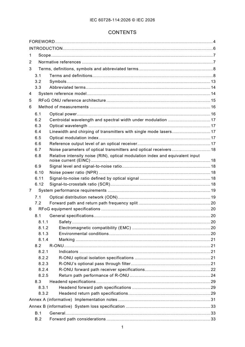
CONTENTS
FOREWORD . 4
INTRODUCTION . 6
1 Scope . 7
2 Normative references . 7
3 Terms, definitions, symbols and abbreviated terms . 8
3.1 Terms and definitions. 8
3.2 Symbols . 13
3.3 Abbreviated terms . 14
4 System reference model . 14
5 RFoG ONU reference architecture . 15
6 Method of measurements . 16
6.1 Optical power . 16
6.2 Centroidal wavelength and spectral width under modulation . 17
6.3 Optical wavelength . 17
6.4 Linewidth and chirping of transmitters with single mode lasers . 17
6.5 Optical modulation index . 17
6.6 Reference output level of an optical receiver . 17
6.7 Noise parameters of optical transmitters and optical receivers . 18
6.8 Relative intensity noise (RIN), optical modulation index and equivalent input
noise current (EINC) . 18
6.9 Signal level and signal-to-noise ratio. 18
6.10 Noise power ratio (NPR) . 18
6.11 Signal-to-noise ratio defined by optical signal . 18
6.12 Signal-to-crosstalk ratio (SCR) . 18
7 System performance requirements . 19
7.1 Optical distribution network (ODN) . 19
7.2 Forward path and return path frequency split . 20
8 RFoG equipment specifications . 20
8.1 General specifications. 20
8.1.1 Safety . 20
8.1.2 Electromagnetic compatibility (EMC) . 20
8.1.3 Environmental conditions . 20
8.1.4 Marking . 21
8.2 R-ONU . 21
8.2.1 Indicators . 21
8.2.2 R-ONU optical isolation specifications . 21
8.2.3 R-ONU’s optional pass through filter . 21
8.2.4 R-ONU forward path receiver specifications . 22
8.2.5 Return path performance of R-ONU . 24
8.3 Headend specifications . 29
8.3.1 Headend forward path specifications . 29
8.3.2 Headend return path specifications . 29
Annex A (informative) Implementation notes . 31
Annex B (informative) System loss specification . 33
B.1 General . 33
B.2 Forward path considerations . 33
B.3 Return path considerations . 34
Annex C (informative) Optical beat interference . 36
C.1 General . 36
C.2 Operating conditions of ODN . 36
C.3 Operating conditions of optical receiver at the headend system . 36
C.4 Operating conditions of CMTS . 37
C.5 Environmental conditions . 37
C.6 Relation between optical transmission loss and OMI . 37
C.7 Design margin of ODN . 38
C.8 Example of system design . 39
C.9 Method of measurement of OBI . 40
C.9.1 Purpose . 40
C.9.2 Measurement setup . 40
C.9.3 Example of measurement conditions. 40
C.9.4 Procedure . 41
C.9.5 Presentation of results . 41
C.10 Method of measurement of OBI (measurement with CW signals) . 41
C.10.1 Purpose . 41
C.10.2 Measurement setup . 41
C.10.3 Procedure . 42
Annex D (informative) Outdoor housings for R-ONU protection . 43
Annex E (informative) Effect of off-state optical power on SNR of transmission signal . 44
Bibliography . 45
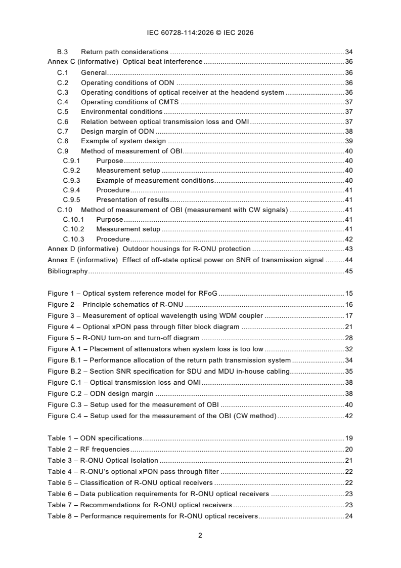
Figure 1 – Optical system reference model for RFoG . 15
Figure 2 – Principle schematics of R-ONU . 16
Figure 3 – Measurement of optical wavelength using WDM coupler . 17
Figure 4 – Optional xPON pass through filter block diagram . 21
Figure 5 – R-ONU turn-on and turn-off diagram . 28
Figure A.1 – Placement of attenuators when system loss is too low . 32
Figure B.1 – Performance allocation of the return path transmission system . 34
Figure B.2 – Section SNR specification for SDU and MDU in-house cabling. 35
Figure C.1 – Optical transmission loss and OMI . 38
Figure C.2 – ODN design margin . 38
Figure C.3 – Setup used for the measurement of OBI . 40
Figure C.4 – Setup used for the measurement of the OBI (CW method) . 42
Table 1 – ODN specifications . 19
Table 2 – RF frequencies . 20
Table 3 – R-ONU Optical Isolation . 21
Table 4 – R-ONU’s optional xPON pass through filter . 22
Table 5 – Classification of R-ONU optical receivers . 22
Table 6 – Data publication requirements for R-ONU optical receivers . 23
Table 7 – Recommendations for R-ONU optical receivers . 23
Table 8 – Performance requirements for R-ONU optical receivers . 24
Table 9 – Classes of optical return path transmitters . 24
Table 10 – Data publication requirements for optical return path transmitters . 24
Table 11 – Performance requirements for optical parameters and interfaces . 25
Table 12 – Electrical properties requirements for R-ONU optical return path
transmitters. 26
Table 13 – R-ONU turn-on and turn-off specifications . 27
Table 14 – Data publication requirements for return path optical receivers . 29
Table 15 – Performance requirements for optical return path receivers . 30
Table C.1 – Operating conditions related to ODN parameters . 36
Table C.2 – Operating conditions related to ODN parameters . 37
Table C.3 – Environmental conditions for system evaluation . 37
Table C.4 – Factors affecting the transmission loss of ODN . 39
Table C.5 – System design example 1 . 39
Table C.6 – System design example 2 . 39
Table C.7 – Example of list of measurement conditions . 40
Table C.8 – Presentation of OBI measurement results . 41
INTERNATIONAL ELECTROTECHNICAL COMMISSION
____________
Cable networks for television signals,
sound signals and interactive services -
Part 114: Optical transmission systems using RFoG technology
FOREWORD
1) The International Electrotechnical Commission (IEC) is a worldwide organization for standardization comprising
all national electrotechnical committees (IEC National Committees). The object of IEC is to promote international
co-operation on all questions concerning standardization in the electrical and electronic fields. To this end and
in addition to other activities, IEC publishes International Standards, Technical Specifications, Technical Reports,
Publicly Available Specifications (PAS) and Guides (hereafter referred to as "IEC Publication(s)"). Their
preparation is entrusted to technical committees; any IEC National Committee interested in the subject dealt with
may participate in this preparatory work. International, governmental and non-governmental organizations liaising
with the IEC also participate in this preparation. IEC collaborates closely with the International Organization for
Standardization (ISO) in accordance with conditions determined by agreement between the two organizations.
2) The formal decisions or agreements of IEC on technical matters express, as nearly as possible, an international
consensus of opinion on the relevant subjects since each technical committee has representation from all
interested IEC National Committees.
3) IEC Publications have the form of recommendations for international use and are accepted by IEC National
Committees in that sense. While all reasonable efforts are made to ensure that the technical content of IEC
Publications is accurate, IEC cannot be held responsible for the way in which they are used or for any
misinterpretation by any end user.
4) In order to promote international uniformity, IEC National Committees undertake to apply IEC Publications
transparently to the maximum extent possible in their national and regional publications. Any divergence between
any IEC Publication and the corresponding national or regional publication shall be clearly indicated in the latter.
5) IEC itself does not provide any attestation of conformity. Independent certification bodies provide conformity
assessment services and, in some areas, access to IEC marks of conformity. IEC is not responsible for any
services carried out by independent certification bodies.
6) All users should ensure that they have the latest edition of this publication.
7) No liability shall attach to IEC or its directors, employees, servants or agents including individual experts and
members of its technical committees and IEC National Committees for any personal injury, property damage or
other damage of any nature whatsoever, whether direct or indirect, or for costs (including legal fees) and
expenses arising out of the publication, use of, or reliance upon, this IEC Publication or any other IEC
Publications.
8) Attention is drawn to the Normative references cited in this publication. Use of the referenced publications is
indispensable for the correct application of this publication.
9) IEC draws attention to the possibility that the implementation of this document may involve the use of (a)
patent(s). IEC takes no position concerning the evidence, validity or applicability of any claimed patent rights in
respect thereof. As of the date of publication of this document, IEC had received notice of (a) patent(s), which
may be required to implement this document. However, implementers are cautioned that this may not represent
the latest information, which may be obtained from the patent database available at https://patents.iec.ch. IEC
shall not be held responsible for identifying any or all such patent rights.
IEC 60728-14 has been prepared by IEC technical committee 100: Audio, video and multimedia
systems and equipment. It is an International Standard.
The text of this International Standard is based on the following documents:
Draft Report on voting
100/4513/FDIS 100/4560/RVD
Full information on the voting for its approval can be found in the report on voting indicated in
the above table.
The language used for the development of this International Standard is English.
This document was drafted in accordance with ISO/IEC Directives, Part 2, and developed in
accordance with ISO/IEC Directives, Part 1 and ISO/IEC Directives, IEC Supplement, available
at www.iec.ch/members_experts/refdocs. The main document types developed by IEC are
described in greater detail at www.iec.ch/publications.
The list of all the parts of the IEC 60728 series, under the general title Cable networks for
television signals, sound signals and interactive services, can be found on the IEC website.
This standard follows closely (where applicable) the ANSI/SCTE 174 2018 standard "Radio
Frequency over Glass / Fiber-to-the-Home (RFoG) Specification / Extension". In agreement with
SCTE major parts of ANSI/SCTE 174:2018 have been copied into this standard.
The committee has decided that the contents of this document will remain unchanged until the
stability date indicated on the IEC website under webstore.iec.ch in the data related to the
specific document. At this date, the document will be
– reconfirmed,
– withdrawn, or
– revised.
___________
SCTE = Society of Cable Telecommunications Engineers
INTRODUCTION
Standards and other deliverables of the IEC 60728 series deal with cable networks, including
equipment and associated methods of measurement for headend reception, processing and
distribution of television and sound signals, and for processing, interfacing and transmitting all
kinds of data signals for interactive services using all applicable transmission media. These
signals are typically transmitted in networks by frequency-multiplexing techniques:
– regional and local broadband cable networks,
– extended satellite and terrestrial television distribution systems,
– individual satellite and terrestrial television receiving systems,
and all kinds of equipment, systems and installations used in such cable networks, distribution
systems and receiving systems.
The extent of this standardization work is from the antennas and/or special signal source inputs
to the headend or other interface points to the network up to the terminal input of the equipment
of the customer's premises.
The standardization work will consider coexistence with users of the RF spectrum in wired and
wireless transmission systems.
The standardization of any user terminals (i.e. tuners, receivers, decoders, multimedia
terminals, etc.) as well as of any coaxial, balanced and optical cables and accessories thereof
is excluded.
The annexes provide the following information:
Annex A describes implementation notes with design considerations based on the content of
this document;
Annex B describes the system loss specification;
Annex C describes multiple CMTS operation;
Annex D gives a design guideline of housings for R-ONU protection;
Annex E contains information on the effect of off-state optical power on the SNR of the
transmission signal.
1 Scope
This part of IEC 60728 describes the system and equipment specification of FTTH/FTTB (fibre
to the home/fibre to the building) networks where information is transmitted in both forward and
return path directions using RF subcarrier multiplexing technology, and where the return path
transmission uses additionally time division multiple access technique imposed by the
transmission of the return path signals using a TDMA (e.g. TDMA mode of DOCSIS) protocol.
Such systems are called RF over glass (RFoG) and consist of an RFoG optical network unit (R-
ONU), an optical distribution network based on xPON structure, and an RFoG optical return
path receiver. This document specifies the basic system parameters and methods of
measurement for RFoG systems in order to assess the system performance and its performance
limits.
The detailed description of physical layer is out of the scope of this document and it does not
include IP transport technologies.
2 Normative references
The following documents are referred to in the text in such a way that some or all of their content
constitutes requirements of this document. For dated references, only the edition cited applies.
For undated references, the latest edition of the referenced document (including any
amendments) applies.
IEC 60068-2 (all parts), Environmental testing
IEC 60529, Degrees of protection provided by enclosures (IP Code)
IEC 60728-2, Cable networks for television signals, sound signals and interactive services -
Part 2: Electromagnetic compatibility of equipment
IEC 60728-3, Cable networks for television signals, sound signals and interactive services -
Part 3: Active wideband equipment for cable networks
IEC 60728-6:2011, Cable networks for television signals, sound signals and interactive
services - Part 6: Optical equipment
IEC 60728-10:2014, Cable networks for television signals, sound signals and interactive
services – Part 10: System performance of return paths
IEC 60728-11, Cable networks for television signals, sound signals and interactive services -
Part 11: Safety
IEC 60728-13:2010, Cable networks for television signals, sound signals and interactive
services - Part 13: Optical systems for broadcast signal transmissions
IEC 60728-113:2023, Cable networks for television signals, sound signals and interactive
services - Part 113: Optical systems for broadcast signal transmissions loaded with digital
channels only
IEC 60728-106:2023, Cable networks for television signals, sound signals and interactive
services - Part 106: Optical equipment for systems loaded with digital channels only
IEC 60794-3-11:2010, Optical fibre cables - Part 3-11: Outdoor cables - Product specification
for duct, directly buried, and lashed aerial single-mode optical fibre telecommunication cables
IEC 60825-1, Safety of laser products - Part 1: Equipment classification and requirements
IEC 61169-2, Radio-frequency connectors - Part 2: Sectional specification - Radio frequency
coaxial connectors of type 9,52
IEC 61169-24, Radio-frequency connectors - Part 24: Sectional specification - Radio-frequency
coaxial connectors with screw coupling, typically for use in 75 Ω cable networks (type F)
IEC 61280-1-1, Fibre optic communication subsystem basic test procedures - Part 1-1: Test
procedures for general communication subsystems - Transmitter output optical power
measurement for single-mode optical fibre cable
IEC 61280-1-3, Fibre optic communication subsystem test procedures - Part 1-3: General
communication subsystems - Measurement of central wavelength, spectral width and additional
spectral characteristics
IEC 61754-4, Fibre optic interconnecting devices and passive components - Fibre optic
connector interfaces - Part 4: Type SC connector family
ISO/IEC/IEEE Standard 8802-3:2021, Standard for Ethernet
3 Terms, definitions, symbols and abbreviated terms
3.1 Terms and definitions
For the purposes of this document, the following terms and definitions apply.
ISO and IEC maintain terminology databases for use in standardization at the following
addresses:
– IEC Electropedia: available at https://www.electropedia.org/
– ISO Online browsing platform: available at https://www.iso.org/obp
3.1.1
equivalent input noise current density
notional input noise current density which, when applied to the input of an ideal noiseless
device, produces an output noise current density equal in value to that observed at the output
of the actual device under consideration
Note 1 to entry: Equivalent input noise current density can be calculated from the RF signal-to-noise ratio (see
IEC 60728-106) of a device or system.
[SOURCE: IEC 60728-14:2014, 3.1.2, modified – The equation in Note 1 to entry and Note 2
entry have been deleted.]
3.1.2
flatness
difference between the maximum and the minimum RF gain or attenuation, not taking into
account the slope within the specified modulation frequency range of a device or system
[SOURCE: IEC 60728-14:2014, 3.1.6]
3.1.3
headend system
system comprising modulators, demodulators, CMTS, an optical transmitter with optional optical
amplifiers and a WDM for the transmission of analogue video as well as digitally modulated
signals located at the central office side of the optical network
Note 1 to entry: The headend system is equipped with an optical return path receiver receiving digitally modulated
signals of data in the return path direction to enable e.g. VoIP, VOD and internet services.
Note 2 to entry: V-OLT is a part of the headend system and deals with video transmission in the forward path only.
[SOURCE: IEC 60728-14:2014, 3.1.7]
3.1.4
local broadband cable network
network designed to provide sound and television signals as well as signals for interactive
services to a local area (e.g. one town or one village)
3.1.5
WDM device
wavelength selective branching device (used in WDM transmission systems) in which optical
signals can be transferred between two predetermined ports, depending on the wavelength of
the signal
3.1.6
noise power ratio
NPR
ratio of the signal power density to the power density of the combined noise and intermodulation
distortion
3.1.7
off-state optical power
residual optical output power emitted from the fibre of the R-ONU when the laser is switched to
off-state
Note 1 to entry: In a typical burst mode transmitter, for fast switching operation, the laser bias may be kept near
the threshold bias level to avoid turn-on and turn-off delays. The off-state optical power affects the system
performance when a large number of transmitters are connected to the same distribution network.
3.1.8
optical distribution network
ODN
passive optical network (PON) mainly consisting of optical fibres and splitters
3.1.9
optical modulation index
index m defined as
φ - φ
h l
m =
(1)
φ + φ
h l
where φ is the highest and φ is the lowest instantaneous optical power of the intensity
h l
modulated optical signal
Note 1 to entry: This definition does not apply to systems where the input signals are converted and transported as
digital baseband signals. In this case, the terms modulation depth or extinction ratio defined in 2.6.79 and 2.7.46 of
IEC TR 61931:1998 are used. A test procedure for extinction ratio is described in IEC 61280-2-2.
[SOURCE: IEC 60728-6:2011,3.1.10, modified – In the definition, "optical modulation" has been
deleted and Note 1 has been omitted.]
3.1.10
optical return loss
return loss
ORL
ratio of the total reflected power to the incident power from an optical fibre, optical device, or
optical system, and defined as:
P
r
−10lg
(2)
P
i
where
is the reflected power;
P
r
P is the incident power.
i
Note 1 to entry: When referring to a reflected power from an individual component, reflectance is the preferred
term.
Note 2 to entry: For the purposes of this standard, the term reflectance is used for optical amplifiers only. The term
optical return loss is used for ports of all other types of equipment.
Note 3 to entry: The term return loss is also used for electrical ports. The definition relates to electrical powers in
this case.
Note 4 to entry: The ratio is expressed in dB.
[SOURCE: IEC TR 61931:1998, 2.6.49, modified – Notes 2 to 4 to entry have been added.]
3.1.11
radio frequency over glass
RFoG
transmission technology on optical networks where information is transmitted in both, forward
and return path directions, using RF subcarrier multiplexing technology
3.1.12
responsivity
ratio of an optical detector’s electrical output to its optical input at a given wavelength
Note 1 to entry: The responsivity is expressed in ampere per watt (A/W) or volts per watt (V/W) of incident radiant
power.
Note 2 to entry: "Sensitivity" is sometimes used as an imprecise synonym for responsivity.
Note 3 to entry: The wavelength interval around the given wavelength may be specified.
[SOURCE: IEC TR 61931:1998, 2.7.56]
3.1.13
relative intensity noise
RIN
ratio of the mean square of the intensity fluctuations in the optical power of a light source to the
square of the mean of the optical output power
−1
Note 1 to entry: The RIN is usually expressed in dB(Hz ) resulting in negative values.
Note 2 to entry: The value for the RIN can be calculated from the results of a RF signal-to-noise measurement for
the system.
[SOURCE: IEC 60728-106:2023, 3.1.24]
3.1.14
RFoG optical network unit
R-ONU
fibre optic terminal comprising an optical receiver for reception of analogue signals and an
optical transmitter for the transmission of analogue signals originating from the customer side
of the optical network, and a coaxial interface for the transmission of analogue signals to the
customer network and reception of analogue signals from the customer network generally
consisting of digital data using a TDMA (e.g. TDMA mode of DOCSIS) protocol
3.1.15
signal-to-crosstalk ratio
SCR
level difference of desired signal level and worst case of other services single frequency
crosstalk signal measured at RF output port of optical receiver
Note 1 to entry: SCR(R ) is defined by the following equation:
SC
R DU−
(3)
SC OS
where
D is the nominal level of the desired signal in dB(µV) at RF output port of optical receiver;
U is the worst-case level of another service’s single frequency crosstalk in dB(µV) at RF output port of the
OS
optical receiver.
Note 2 to entry: SCR is expressed in dB.
3.1.16
signal-to-noise ratio
SNR
level difference of desired signal level and noise level
Note 1 to entry: SNR is defined for both analogue and digital modulated signals in IEC 60728-13.
[SOURCE: IEC 60728-1:2014, 3.1.80, modified – The term has been replaced.]
=
3.1.17
slope
gain or attenuation difference at two defined frequencies between two ports of a device or
system
Note 1 to entry: In this document, the term slope relates only to the electrical gain or attenuation of equipment.
Note 2 to entry: In equipment for cable networks, a line of best fit of the amplitude frequency response is considered
at the band limits.
[SOURCE: IEC 60728-106:2023, 3.1.29]
3.1.18
stimulated Brillouin scattering
SBS
non-linear scattering of optical radiation characterized by a frequency shift as for the Raman
scattering, but accompanied by a lower frequency (acoustical) vibration of the medium lattice;
the light is scattered backward with respect to the incident radiation
Note 1 to entry: In silica fibres, the frequency shift is typically around 10 GHz.
[SOURCE: IEC TR 61931:1998, 2.1.88]
3.1.19
wavelength
distance covered in a period by the wavefront of a harmonic plane wave
Note 1 to entry: The wavelength λ of light in vacuum is given by
c
λ =
(4)
f
where
c is the speed of light in vacuum (c ≈ 2,997 92 × 10 m/s);
f is the optical frequency.
Note 2 to entry: Although the wavelength in dielectric material such as fibres is shorter than in vacuum, only the
wavelength of light in vacuum is used.
[SOURCE: IEC TR 61931:1998, 2.2.9, modified – Notes to entry have been added.]
・・・
・・・
3.2 Symbols
The following graphical symbols are used in the figures of this document. These symbols are
either listed in IEC 60617 or based on symbols defined in IEC 60617.
Electrical to optical converter Optical to electrical converter
E O
(Optical transmitter) (Optical receiver)
based on based on
E
O
IEC 60617-S00213:2001-07 IEC 60617-S00213:2001-07
O E
E
O
Optical amplifier
based on Optical fibre
IEC 60617-S00127:2001-07 and IEC 60617-S01318:2001-07
IEC 60617-S01239:2001-07
Low-pass filter High-pass filter
IEC 60617-S01248:2001-07, IEC 60617-S01247:2001-07,
modified modified
Directional coupler
MUX Wavelength-division multiplexer
based on
(WDM)
λ
IEC 60617-S00059:2001-07 and
IEC 60617- S01933:2025-02
IEC 60617-S01193:2001-07
Electrical spectrum analyser Optical spectrum analyser
based on based on
P(f) P(λ)
IEC 60617-S00059:2001-07 and IEC 60617-S00059:2001-07 and
IEC 60617-S00910:2001-07 IEC 60617-S00910:2001-07
Polarization control device Variable attenuator
A
IEC 60617-S01934:2025-12 IEC 60617-S01245:2001-07
Sine-wave generator
based on
G
Splitter, two-way
IEC 60617-S00899:2001-07 and
IEC 60617-S01334:2001-07
IEC 60617-S01403:2001-09
Optical splitter based on
[IEC TR 61930:1998 3.33.1] Splitter, three-way
IEC 60617-S00435:2001-07
3.3 Abbreviated terms
The following abbreviated terms are used in this standard:
AC alternating current AGC automatic gain control
CM cable modem CMTS cable modem termination system
CW continuous wave DC direct current
DFB distributed feedback DS downstream
EINC equivalent input noise current EMC electromagnetic compatibility
EPON Ethernet passive optical network FTTB Fibre to the building
(defined in ISO/IEC/IEEE Standard
8802-3:2021)
FTTH fibre to the home GEPON Gigabit Ethernet passive optical
network
(defined in ISO/IEC/IEEE Standard
8802-3:2021)
GPON Gigabit-capable passive optical networks HFC hybrid fibre coaxial
(defined in ITU-T Recommendation G.984)
MDU multiple dwelling unit NPR noise power ratio
OBI optical beat interference ODN optical distribution network
OFDM orthogonal frequency division multiplex OMI optical modulation index
ONU optical network unit PON passive optical network
QAM quadrature amplitude modulation QPSK quadrature phase shift keying
RF radio frequency RFoG RF over glass
RIN relative intensity noise R-ONU RFoG optical network unit
R-RRX RFoF return path receiver Rx (optical) receiver
SBS stimulated Brillouin scattering SCR signal-to-crosstalk ratio
SDU single dwelling unit SNR Signal-to-noise ratio
TDMA Time division multiple access Tx (optical) transmitter
US upstream V-OLT video optical line termination unit
V-ONU video optical network unit WDM wavelength division multiplexing
XG-PON 10-Gigabit-capable passive optical network xPON x- passive optical network,
(defined in ITU-T Recommendation G.987)
"x" = G, E, 10 G, 10 GE, etc.
4 System reference model
Figure 1 shows the optical system reference model for forward path signal transmission and
return path signal transmission. The forward path signal transmission system is the subject of
IEC 60728-13. Compared to IEC 60728-13:2010, Figure 1, the V-ONU has been replaced by an
R-ONU which includes a WDM and a burst mode return path transmitter in addition to the
V-ONU functionalities. The R-ONU is capable of transmitting interactive signals and is therefore
connected to a cable modem (CM) as well.
Figure 1 – Optical system reference model for RFoG
Figure 1 illustrates the reference architecture of the system. In the reference architecture, the
headend system, the start of the RFoG system, comprises an optical forward path transmitter
operating nominally on 1 550 nm, optical amplification and splitting as appropriate, and an
optical return path receiver which receives optical return path signals on λ (defined below),
up
and converts them to RF form. The wavelength division multiplexer used to combine and
separate the two wavelengths is a part of the headend system. For the purpose of optical loss
budget calculation, the WDM optical loss shall be included in the total loss of ODN, consistent
with the ODN definition in EPON and GPON.
Specifications contained in this document apply between the electrical signal terminal of the
headend system and the RF electrical terminal from the R-ONU. The system designer is
responsible for making sure that the effects of any signal degradation are properly accounted
for in the network design. Return path system performance will vary by choice of optical return
path receiver hardware. Receiver noise performance and technology choice determines
interoperability. The ODN is defined to start at the input of the WDM at the optical headend
system and to end at the pigtail on the R-ONU at the home.
The ODN is shown with a single point splitter. However, the ODN may also be implemented as
a series of optical taps or as a multi-layer splitter, such as a 1:4 split followed by a set of 1:8
splitters at a different location. As long as the maximum distance, loss budget, and split ratio
are respected, the architecture of the splitting is at the discretion of the operator.
5 RFoG ONU reference architecture
Figure 2 illustrates the R-ONU reference architecture. The R-ONU comprises a wavelength
division multiplexer (WDM) which separates the optical forward path signal at 1 550 nm nominal
and the optical return path signal at λ . The WDM optionally passes optical signals to and from
up
the PON port for connection to an ONT. The forward path receiver recovers RF forward path
signals from the 1 550 nm (nominal) forward path optical carrier and supplies them to the output
via a diplexer.
Figure 2 – Principle schematics of R-ONU
The low port of the diplexer supplies return path signals to a return path transmitter whose
output is at λ . It also supplies signals to a signal detector, whose job it is to turn on the return
up
path transmitter when RF signals in the return path band are detected at a level exceeding a
specified minimum threshold.
The specification permits either of two return path wavelengths λ . One permitted wavelength
up
is 1 310 nm nominal, and the other is 1 610 nm nominal. Use of 1 610 nm permits an optional
overlay of an RFoG system with either an in ISO/IEC/IEEE 8802-3:2021 EPON system or an
ITU G.984 GPON system. Both systems use 1 310 nm or lower wavelengths for return path
data communications. Both return path wavelengths work with the same physical network. Note
that if the 1 310 nm return path wavelength is used for RFoG, then neither EPON nor GPON
will coexist in the same physical passive optical network.
For compatibility with 10G-EPON or XG-PON systems, the 1 610 nm return path option may be
used, but might need an external optical trap at 1 577 nm (nominal) to eliminate that forward
path carrier. Alternatively, a manufacturer may offer an R-ONU with a built-in optical trap, or
the operator may choose to deploy RFoG and 10GEPON or XG-PON on separate networks with
co-located splitting. Furthermore, a manufacturer may optionally include a 10G-E/XG-PON
WDM in the R-ONU to provide PON pass-through.
6 Method of measurements
6.1 Optical power
The measurement of optical power at single wavelength shall be carried out in accordance with
IEC 61280-1-1. For measuring the total average optical power of multiple wavelengths
emanating from the end of a test fibre, the method described in IEC 60728-13 shall be used.
NOTE In general, there is no wavelength selectivity in the optical power meter that is calculated and is displayed
as total optical power. Therefore, it is necessary to separate the wavelengths using a WDM coupler or a WDM filter
if multiple wavelengths are present. In that case, it is necessary to compensate the loss of the WDM filter used.
6.2 Centroidal wavelength and spectral width under modulation
For measuring the centroidal wavelength λ of the spectrum and the spectral width Δλ of a
transmitter under modulation, the method described in IEC 61280-1-3 shall be used. The
centroidal wavelength and the spectral width shall be expressed in nanometres. This method is
not suitable for light sources and transmitters with very narrow spectral width (such as single
mode lasers typically used for forward path transmission) or for measuring the chirping of
transmitters.
6.3 Optical wavelength
The optical wavelength, in the RFoG system, shall be measured following the description given
below.
If a single R-ONU is used to receive multiple wavelengths simultaneously without any WDM
filter, a test WDM filter shall be used to measure the individual optical wavelength at the input
of R-ONU. The measurement setup is shown in Figure 3.
Figure 3 – Measurement of optical wavelength using WDM coupler
For measuring the central wavelength λ of the spe
...
IEC 60728-114 ®
Edition 1.0 2026-08
NORME
INTERNATIONALE
Réseaux de distribution par câbles pour signaux de télévision, signaux de
radiodiffusion sonore et services interactifs -
Partie 114: Systèmes de transmission optique qui utilisent la technologie RFoG
ICS 33.160.01; 33.180.20 ISBN 978-2-8327-1457-7
Droits de reproduction réservés. Sauf indication contraire, aucune partie de cette publication ne peut être reproduite ni
utilisée sous quelque forme que ce soit et par aucun procédé, électronique ou mécanique, y compris la photocopie et
les microfilms, sans l'accord écrit de l'IEC ou du Comité national de l'IEC du pays du demandeur. Si vous avez des
questions sur le copyright de l'IEC ou si vous désirez obtenir des droits supplémentaires sur cette publication, utilisez
les coordonnées ci-après ou contactez le Comité national de l'IEC de votre pays de résidence.
IEC Secretariat Tel.: +41 22 919 02 11
3, rue de Varembé info@iec.ch
CH-1211 Geneva 20 www.iec.ch
Switzerland
A propos de l'IEC
La Commission Electrotechnique Internationale (IEC) est la première organisation mondiale qui élabore et publie des
Normes internationales pour tout ce qui a trait à l'électricité, à l'électronique et aux technologies apparentées.
A propos des publications IEC
Le contenu technique des publications IEC est constamment revu. Veuillez vous assurer que vous possédez l’édition la
plus récente, un corrigendum ou amendement peut avoir été publié.
Recherche de publications IEC - IEC Products & Services Portal - products.iec.ch
webstore.iec.ch/advsearchform Découvrez notre puissant moteur de recherche et consultez
La recherche avancée permet de trouver des publications gratuitement tous les aperçus des publications, symboles
IEC en utilisant différents critères (numéro de référence, graphiques et le glossaire. Avec un abonnement, vous aurez
texte, comité d’études, …). Elle donne aussi des toujours accès à un contenu à jour adapté à vos besoins.
informations sur les projets et les publications remplacées
ou retirées. Electropedia - www.electropedia.org
Le premier dictionnaire d'électrotechnologie en ligne au
IEC Just Published - webstore.iec.ch/justpublished monde, avec plus de 22 500 articles terminologiques en
Restez informé sur les nouvelles publications IEC. Just anglais et en français, ainsi que les termes équivalents
dans 25 langues additionnelles. Egalement appelé
Published détaille les nouvelles publications parues.
Disponible en ligne et une fois par mois par email. Vocabulaire Electrotechnique International (IEV) en ligne.
Service Clients - webstore.iec.ch/csc
Si vous désirez nous donner des commentaires sur cette
publication ou si vous avez des questions contactez-
nous: sales@iec.ch.
SOMMAIRE
AVANT-PROPOS . 4
INTRODUCTION . 6
1 Domaine d'application . 7
2 Références normatives . 7
3 Termes, définitions, symboles et abréviations . 8
3.1 Termes et définitions . 8
3.2 Symboles . 13
3.3 Abréviations . 14
4 Modèle de référence du système . 15
5 Architecture de référence de l'ONU RFoG . 16
6 Méthode de mesurage . 17
6.1 Puissance optique . 17
6.2 Longueur d'onde centroïdale et largeur spectrale sous modulation . 17
6.3 Longueur d'onde optique . 17
6.4 Largeur de raie et fluctuation de longueur d'onde des émetteurs avec lasers
unimodaux . 18
6.5 Indice de modulation optique . 18
6.6 Niveau de sortie de référence d'un récepteur optique . 18
6.7 Paramètres de bruit des émetteurs optiques et des récepteurs optiques . 18
6.8 Bruit d'intensité relatif (RIN), indice de modulation optique et courant
d'entrée équivalent au bruit (EINC) . 18
6.9 Niveau du signal et rapport signal sur bruit . 18
6.10 Rapport bruit sur puissance (NPR) . 19
6.11 Rapport signal sur bruit défini par le signal optique . 19
6.12 Rapport signal sur diaphonie (SCR) . 19
7 Exigences de performance du système . 20
7.1 Réseau de distribution optique (ODN) . 20
7.2 Répartition de la fréquence en voie directe et en voie de retour . 21
8 Spécifications du matériel RFoG . 21
8.1 Spécifications générales . 21
8.1.1 Sécurité . 21
8.1.2 Compatibilité électromagnétique (CEM) . 21
8.1.3 Conditions d'environnement . 22
8.1.4 Marquage . 22
8.2 R-ONU . 22
8.2.1 Indicateurs. 22
8.2.2 Spécifications de l'isolement optique de la R-ONU. 22
8.2.3 Filtre passerelle facultatif de la R-ONU . 22
8.2.4 Spécifications du récepteur à voie directe de la R-ONU . 23
8.2.5 Performances en voie de retour de la R-ONU . 25
8.3 Spécifications de la tête de réseau . 30
8.3.1 Spécifications de la voie directe de la tête de réseau . 30
8.3.2 Spécifications de la voie de retour de la tête de réseau . 30
Annexe A (informative) Notes de mise en œuvre . 32
Annexe B (informative) Spécification des pertes du système . 35
B.1 Généralités . 35
B.2 Aspects relatifs à la voie directe . 35
B.3 Aspects relatifs à la voie de retour . 36
Annexe C (informative) Interférence de battement optique . 39
C.1 Généralités . 39
C.2 Conditions de fonctionnement de l'ODN . 39
C.3 Conditions de fonctionnement du récepteur optique au niveau du système
de tête de réseau . 39
C.4 Conditions de fonctionnement du CMTS . 40
C.5 Conditions d'environnement . 40
C.6 Relation entre la perte de transmission optique et l'OMI . 40
C.7 Marge de conception de l'ODN . 41
C.8 Exemple de conception de système . 42
C.9 Méthode de mesurage de l'OBI . 43
C.9.1 Objet . 43
C.9.2 Montage de mesure . 43
C.9.3 Exemple de conditions de mesurage. 44
C.9.4 Procédure . 44
C.9.5 Présentation des résultats . 45
C.10 Méthode de mesurage de l'OBI (mesurage avec des signaux CW) . 45
C.10.1 Objet . 45
C.10.2 Montage de mesure . 45
C.10.3 Procédure . 46
Annexe D (informative) Boîtiers extérieurs de protection des R-ONU . 47
Annexe E (informative) Effet de la puissance optique à l'état hors tension sur le SNR
du signal de transmission . 48
Bibliographie . 50
Figure 1 – Modèle de référence du système optique pour RFoG . 15
Figure 2 – Schéma de principe de R-ONU . 16
Figure 3 – Mesurage d'une longueur d'onde optique avec un coupleur MRL . 18
Figure 4 – Schéma fonctionnel du filtre passerelle xPON facultatif . 23
Figure 5 – Schéma de mise sous tension et de mise hors tension de la R-ONU . 30
Figure A.1 – Positionnement des affaiblisseurs lorsque les pertes du système sont trop
faibles . 34
Figure B.1 – Attribution des performances du système de transmission par voie de
retour . 37
Figure B.2 – Spécification du SNR de section pour le câblage interne d'une SDU et
d'une MDU . 38
Figure C.1 – Perte de transmission optique et OMI . 41
Figure C.2 – Marge de conception de l'ODN . 42
Figure C.3 – Montage utilisé pour le mesurage de l'OBI . 44
Figure C.4 – Montage utilisé pour le mesurage de l'OBI (méthode CW) . 46
Tableau 1 – Spécifications de l'ODN . 20
Tableau 2 – Fréquences RF . 21
Tableau 3 – Isolement optique de la R-ONU . 22
Tableau 4 – Filtre passerelle xPON facultatif de la R-ONU . 23
Tableau 5 – Classification des récepteurs optiques de R-ONU . 23
Tableau 6 – Exigences relatives à la publication des données pour les récepteurs
optiques de R-ONU . 24
Tableau 7 – Recommandations pour les récepteurs optiques de R-ONU . 24
Tableau 8 – Exigences de performances pour les récepteurs optiques de R-ONU . 25
Tableau 9 – Classes d'émetteurs optiques à voie de retour . 25
Tableau 10 – Exigences relatives à la publication des données pour les émetteurs
optiques à voie de retour . 26
Tableau 11 – Exigences de performances pour les paramètres et les interfaces
optiques . 26
Tableau 12 – Exigences relatives aux propriétés électriques des émetteurs optiques à
voie de retour de R-ONU . 27
Tableau 13 – Spécifications de mise sous tension et de mise hors tension de la R-ONU . 28
Tableau 14 – Exigences relatives à la publication des données pour les récepteurs
optiques à voie de retour . 31
Tableau 15 – Exigences de performances pour les émetteurs optiques à voie de retour . 31
Tableau C.1 – Conditions de fonctionnement associées aux paramètres de l'ODN. 39
Tableau C.2 – Conditions de fonctionnement associées aux paramètres de l'ODN. 40
Tableau C.3 – Conditions d'environnement pour l'évaluation du système . 40
Tableau C.4 – Facteurs qui influencent la perte de transmission de l'ODN . 42
Tableau C.5 – Exemple 1 de conception de système . 43
Tableau C.6 – Exemple 2 de conception de système . 43
Tableau C.7 – Exemple de liste de conditions de mesurage . 44
Tableau C.8 – Présentation des résultats de mesure de l'OBI . 45
COMMISSION ÉLECTROTECHNIQUE INTERNATIONALE
____________
Réseaux de distribution par câbles pour signaux de télévision,
signaux de radiodiffusion sonore et services interactifs -
Partie 114: Systèmes de transmission optique
qui utilisent la technologie RFoG
AVANT-PROPOS
1) La Commission Électrotechnique Internationale (IEC) est une organisation mondiale de normalisation composée
de l'ensemble des comités électrotechniques nationaux (Comités nationaux de l'IEC). L'IEC a pour objet de
favoriser la coopération internationale pour toutes les questions de normalisation dans les domaines de
l'électricité et de l'électronique. À cet effet, l'IEC – entre autres activités – publie des Normes internationales,
des Spécifications techniques, des Rapports techniques, des Spécifications accessibles au public (PAS) et des
Guides (ci-après dénommés "Publication(s) de l'IEC"). Leur élaboration est confiée à des comités d'études, aux
travaux desquels tout Comité national intéressé par le sujet traité peut participer. Les organisations
internationales, gouvernementales et non gouvernementales, en liaison avec l'IEC, participent également aux
travaux. L'IEC collabore étroitement avec l'Organisation Internationale de Normalisation (ISO), selon des
conditions fixées par accord entre les deux organisations.
2) Les décisions ou accords officiels de l'IEC concernant les questions techniques représentent, dans la mesure du
possible, un accord international sur les sujets étudiés, étant donné que les Comités nationaux de l'IEC intéressés
sont représentés dans chaque comité d'études.
3) Les Publications de l'IEC se présentent sous la forme de recommandations internationales et sont agréées
comme telles par les Comités nationaux de l'IEC. Tous les efforts raisonnables sont entrepris afin que l'IEC
s'assure de l'exactitude du contenu technique de ses publications; l'IEC ne peut pas être tenue responsable de
l'éventuelle mauvaise utilisation ou interprétation qui en est faite par un quelconque utilisateur final.
4) Dans le but d'encourager l'uniformité internationale, les Comités nationaux de l'IEC s'engagent, dans toute la
mesure possible, à appliquer de façon transparente les Publications de l'IEC dans leurs publications nationales
et régionales. Toutes divergences entre toutes Publications de l'IEC et toutes publications nationales ou
régionales correspondantes doivent être indiquées en termes clairs dans ces dernières.
5) L'IEC elle-même ne fournit aucune attestation de conformité. Des organismes de certification indépendants
fournissent des services d'évaluation de conformité et, dans certains secteurs, accèdent aux marques de
conformité de l'IEC. L'IEC n'est responsable d'aucun des services effectués par les organismes de certification
indépendants.
6) Tous les utilisateurs doivent s'assurer qu'ils sont en possession de la dernière édition de cette publication.
7) Aucune responsabilité ne doit être imputée à l'IEC, à ses administrateurs, employés, auxiliaires ou mandataires,
y compris ses experts particuliers et les membres de ses comités d'études et des Comités nationaux de l'IEC,
pour tout préjudice causé en cas de dommages corporels et matériels, ou de tout autre dommage de quelque
nature que ce soit, directe ou indirecte, ou pour supporter les coûts (y compris les frais de justice) et les dépenses
découlant de la publication ou de l'utilisation de cette Publication de l'IEC ou de toute autre Publication de l'IEC,
ou au crédit qui lui est accordé.
8) L'attention est attirée sur les références normatives citées dans cette publication. L'utilisation de publications
référencées est obligatoire pour une application correcte de la présente publication.
9) L'IEC attire l'attention sur le fait que la mise en application du présent document peut entraîner l'utilisation d'un
ou de plusieurs brevets. L'IEC ne prend pas position quant à la preuve, à la validité et à l'applicabilité de tout
droit de brevet revendiqué à cet égard. À la date de publication du présent document, l'IEC avait reçu notification
qu'un ou plusieurs brevets pouvaient être nécessaires à sa mise en application. Toutefois, il y a lieu d'avertir les
responsables de la mise en application du présent document que des informations plus récentes sont
susceptibles de figurer dans la base de données de brevets, disponible à l'adresse https://patents.iec.ch. L'IEC
ne saurait être tenue pour responsable de ne pas avoir identifié de tels droits de brevets.
L'IEC 60728-14 a été établie par le comité d'études 100 de l'IEC: Systèmes et équipements
audio, vidéo et services de données. Il s'agit d'une Norme internationale.
Le texte de cette Norme internationale est issu des documents suivants:
Projet Rapport de vote
100/4513/FDIS 100/4560/RVD
Le rapport de vote indiqué dans le tableau ci-dessus donne toute information sur le vote ayant
abouti à son approbation.
La langue employée pour l'élaboration de cette Norme internationale est l'anglais.
Ce document a été rédigé selon les Directives ISO/IEC, Partie 2, il a été développé selon les
Directives ISO/IEC, Partie 1 et les Directives ISO/IEC, Supplément IEC, disponibles sous
www.iec.ch/members_experts/refdocs. Les principaux types de documents développés par
l'IEC sont décrits plus en détail sous www.iec.ch/publications.
Une liste de toutes les parties de la série IEC 60728, publiées sous le titre général Réseaux de
distribution par câbles pour signaux de télévision, signaux de radiodiffusion sonore et services
interactifs, se trouve sur le site web de l'IEC.
La présente norme suit étroitement (le cas échéant) la norme ANSI/SCTE 174 2018, intitulée
"Radio Frequency over Glass / Fiber-to-the-Home (RFoG) Specification / Extension" (disponible
en anglais seulement). En accord avec la SCTE , les principales parties de
l'ANSI/SCTE 174:2018 ont été copiées dans la présente norme.
Le comité a décidé que le contenu de ce document ne sera pas modifié avant la date de stabilité
indiquée sur le site web de l'IEC sous webstore.iec.ch dans les données relatives au document
recherché. À cette date, le document sera
– reconduit,
– supprimé, ou
– révisé.
___________
SCTE = Society of Cable Telecommunications Engineers.
INTRODUCTION
Les normes et autres publications de la série IEC 60728 traitent des réseaux de distribution par
câbles, notamment des matériels et des méthodes de mesurage associées pour la réception
en tête de réseau, le traitement et la distribution de signaux de télévision et de signaux de
radiodiffusion sonore, ainsi que pour le traitement, l'interfaçage et la transmission de tous types
de signaux de données pour les services interactifs qui utilisent tout support de transmission
applicable. Ces signaux sont habituellement transmis dans les réseaux par des techniques de
multiplexage fréquentiel:
– les réseaux régionaux et locaux de distribution par câbles à large bande;
– les systèmes étendus de distribution de télévision terrestre et par satellite;
– les systèmes de réception individuelle de télévision terrestre et par satellite;
et tous types de matériels, de systèmes et d'installations utilisés dans de tels réseaux de
distribution par câbles, systèmes de distribution et systèmes de réception.
Ce travail de normalisation s'étend des antennes et/ou des entrées pour source de signal
particulière à l'entrée de terminal de l'équipement chez le client en passant par la tête de réseau
ou d'autres points d'interface d'accès au réseau.
Le travail de normalisation prend en compte la coexistence des utilisateurs du spectre de RF
dans les systèmes de transmission filaires et sans fil.
Le présent document ne couvre donc pas la normalisation des terminaux d'utilisateur
(syntoniseurs, récepteurs, décodeurs, terminaux multimédias, etc.), des câbles coaxiaux,
symétriques et optiques, ainsi que de leurs accessoires.
Les annexes fournissent les informations suivantes:
Annexe A décrit des notes de mise en œuvre avec des considérations relatives à la
conception fondées sur le contenu du présent document;
Annexe B décrit la spécification des pertes du système;
Annexe C décrit le fonctionnement de CMTS multiples;
Annexe D fournit une ligne directrice pour la conception des boîtiers de protection des R-ONU;
Annexe E contient des informations sur l'effet de la puissance optique à l'état hors tension sur
le SNR du signal de transmission.
1 Domaine d'application
La présente partie de l'IEC 60728 décrit les spécifications des systèmes et matériels des
réseaux DFA/DFI (desserte par fibre de l'abonné/desserte par fibre de l'immeuble), où les
informations sont transmises dans les deux sens, en voie directe et en voie de retour, à l'aide
de la technologie de multiplexage des sous-porteuses RF, et où la transmission en voie de
retour utilise en outre la technique d'accès multiple à répartition temporelle, imposée par la
transmission des signaux en voie de retour à l'aide d'un protocole TDMA (mode TDMA de la
DOCSIS, par exemple). Ces systèmes dits RF sur verre (RFoG) se composent d'une unité de
réseau optique RFoG (R-ONU), d'un réseau de distribution optique fondé sur la structure xPON
et d'un récepteur optique à voie de retour RFoG. Le présent document spécifie les paramètres
de base du système et les méthodes de mesurage des systèmes RFoG, afin d'évaluer les
performances du système et ses limites de performances.
La description précise de la couche physique ne fait pas partie du domaine d'application du
présent document et n'inclut pas les technologies de transport IP.
2 Références normatives
Les documents suivants sont cités dans le texte de sorte qu'ils constituent, pour tout ou partie
de leur contenu, des exigences du présent document. Pour les références datées, seule
l'édition citée s'applique. Pour les références non datées, la dernière édition du document de
référence s'applique (y compris les éventuels amendements).
IEC 60068-2 (toutes les parties), Essais d'environnement
IEC 60529, Degrés de protection procurés par les enveloppes (Code IP)
IEC 60728-2, Réseaux de distribution par câbles pour signaux de télévision, signaux de
radiodiffusion sonore et services interactifs - Partie 2: Electromagnetic compatibility for
equipment (disponible en anglais seulement)
IEC 60728-3, Réseaux de distribution par câbles pour signaux de télévision, signaux de
radiodiffusion sonore et services interactifs - Partie 3: Matériel actif à large bande pour réseaux
de distribution par câbles
IEC 60728-6:2011, Réseaux de distribution par câbles pour signaux de télévision, signaux de
radiodiffusion sonore et services interactifs - Partie 6: Matériels optiques
IEC 60728-10:2014, Réseaux de distribution par câbles pour signaux de télévision, signaux de
radiodiffusion sonore et services interactifs - Partie 10: Performances des systèmes de voie de
retour
IEC 60728-11, Réseaux de distribution par câbles pour signaux de télévision, signaux de
radiodiffusion sonore et services interactifs - Partie 11: Sécurité
IEC 60728-13:2010, Réseaux de distribution par câbles pour signaux de télévision, signaux de
radiodiffusion sonore et services interactifs - Partie 13: Systèmes optiques pour la transmission
de signaux de diffusion
IEC 60728-113:2023, Réseaux de distribution par câbles pour signaux de télévision, signaux
de radiodiffusion sonore et services interactifs - Partie 113: Systèmes optiques pour la
transmission de signaux de diffusion soumis à une charge de porteuses exclusivement
numériques
IEC 60728-106:2023, Réseaux de distribution par câbles pour signaux de télévision, signaux
de radiodiffusion sonore et services interactifs - Partie 106: Matériel optique pour systèmes
soumis à une charge de porteuses exclusivement numériques
IEC 60794-3-11:2010, Câbles à fibres optiques - Partie 3-11: Câbles extérieurs - Spécification
de produits pour les câbles de télécommunication à fibres optiques unimodales, destinés à être
installés dans des conduites, directement enterrés et en aériens ligaturés
IEC 60825-1, Sécurité des appareils à laser - Partie 1: Classification des matériels et exigences
IEC 61169-2, Connecteurs pour fréquences radioélectriques - Partie 2: Spécification
intermédiaire - Connecteurs coaxiaux pour fréquences radioélectriques de série 9,52
IEC 61169-24, Connecteurs pour fréquences radioélectriques - Partie 24: Spécification
intermédiaire - Connecteurs coaxiaux pour fréquences radioélectriques avec couplage à vis,
typiquement utilisés dans des réseaux de distribution par câbles de 75 Ω (type F)
IEC 61280-1-1, Procédures d'essai de base des sous-systèmes de télécommunication à fibres
optiques - Partie 1-1: Procédures d'essai des sous-systèmes généraux de télécommunication -
Mesure de la puissance optique des émetteurs couplés à des câbles à fibres optiques
unimodales
IEC 61280-1-3, Procédures d'essai des sous-systèmes de télécommunication fibroniques -
Partie 1-3: Sous-systèmes généraux de télécommunication - Mesure de la longueur d'onde
centrale, de la largeur spectrale et des caractéristiques spectrales supplémentaires
IEC 61754-4, Dispositifs d'interconnexion et composants passifs fibroniques - Interfaces de
connecteurs fibroniques - Partie 4: Famille de connecteurs de type SC
Norme ISO/IEC/IEEE 8802-3:2021, Norme pour Ethernet
3 Termes, définitions, symboles et abréviations
3.1 Termes et définitions
Pour les besoins du présent document, les termes et définitions suivants s'appliquent.
L'ISO et l'IEC tiennent à jour des bases de données terminologiques destinées à être utilisées
en normalisation, consultables aux adresses suivantes:
– IEC Electropedia: disponible à l'adresse https://www.electropedia.org/
– ISO Online browsing platform: disponible à l'adresse https://www.iso.org/obp
3.1.1
densité de courant d'entrée équivalente au bruit
densité de courant de bruit d'entrée théorique qui, lorsqu'elle est appliquée à l'entrée d'un
dispositif non résonnant théorique, produit une densité de courant de bruit de sortie égale en
valeur à la densité observée à la sortie du dispositif réel à l'étude
Note 1 à l'article: La densité de courant d'entrée équivalente au bruit peut être calculée à partir du rapport signal RF
sur bruit (voir l'IEC 60728-106) d'un dispositif ou d'un système.
[SOURCE: IEC 60728-14:2014, 3.1.2, modifié – Les équations dans la Note 1 à l'article et dans
la Note 2 à l'article ont été supprimées.]
3.1.2
planéité
différence entre le gain ou l'affaiblissement RF maximal et minimal sans tenir compte de la
pente dans la plage de fréquences de modulation spécifiée d'un dispositif ou d'un système
[SOURCE: IEC 60728-14:2014, 3.1.6]
3.1.3
système de tête de réseau
système composé de modulateurs, de démodulateurs, d'un CMTS, d'un émetteur optique avec
amplificateurs optiques facultatifs et d'un MRL pour la transmission de signaux vidéo
analogiques ainsi que de signaux modulés numériquement situés du côté central du réseau
optique
Note 1 à l'article: Le système de tête de réseau est équipé d'un récepteur optique à voie de retour qui reçoit des
signaux de données modulés numériquement dans le sens de la voie de retour afin d'activer, par exemple, les
services VoIP, VOD et Internet.
Note 2 à l'article: La V-OLT fait partie du système de tête de réseau et couvre uniquement la transmission vidéo en
voie directe.
[SOURCE: IEC 60728-14:2014, 3.1.7]
3.1.4
réseau local de distribution par câbles à large bande
réseau conçu pour fournir des signaux de radiodiffusion sonore et de télévision ainsi que des
signaux pour services interactifs à une zone locale (une ville ou un village, par exemple)
3.1.5
dispositif MRL
dispositif de couplage qui sélectionne les longueurs d'onde (utilisé dans les systèmes de
transmission MRL) et dans lequel les signaux optiques peuvent être transférés entre deux
accès prédéterminés, selon la longueur d'onde du signal
3.1.6
rapport bruit sur puissance
NPR
rapport de la densité de puissance du signal à la densité de puissance du bruit combiné et de
la distorsion d'intermodulation
Note 1 à l'article: L'abréviation "NPR" est dérivée du terme anglais développé correspondant "noise power ratio".
3.1.7
puissance optique à l'état hors tension
puissance de sortie optique résiduelle émise par la fibre de la R-ONU lorsque le laser passe à
l'état hors tension
Note 1 à l'article: Dans un émetteur en mode salve type, pour un fonctionnement à commutation rapide, la
polarisation du laser peut être maintenue à proximité du niveau seuil de polarisation afin d'éviter les retards de mise
sous tension et de mise hors tension. La puissance optique à l'état hors tension influe sur les performances du
système lorsqu'un grand nombre d'émetteurs sont connectés au même réseau de distribution.
3.1.8
réseau de distribution optique
ODN
réseau optique passif (PON) constitué principalement de fibres et de répartiteurs optiques
Note 1 à l'article: L'abréviation "ODN" est dérivée du terme anglais développé correspondant "optical distribution
network".
3.1.9
indice de modulation optique
indice m défini par
φ - φ
h l
m =
(1)
φ + φ
h l
où φ est la plus grande et φ est la plus petite puissance optique instantanée du signal optique
h l
modulé en intensité
Note 1 à l'article: Cette définition ne s'applique pas aux systèmes où les signaux d'entrée sont convertis et
acheminés sous la forme de signaux numériques en bande de base. Dans ce cas, les termes profondeur de
modulation ou rapport d'extinction, définis en 2.6.79 et en 2.7.46 de l'IEC TR 61931:1998 sont utilisés. Une
procédure d'essai pour le rapport d'extinction est décrite dans l'IEC 61280-2-2.
[SOURCE: IEC 60728-6:2011, 3.1.10, modifié – Dans la définition, le terme "de modulation
optique" a été supprimé et la Note 1 a été omise.]
3.1.10
coefficient de réflexion
rapport de la puissance réfléchie totale à la puissance incidente provenant d'une fibre, d'un
dispositif ou d'un système optiques et représenté par la formule
P
r
−10lg
(2)
P
i
où
P est la puissance réfléchie;
r
P est la puissance incidente.
i
Note 1 à l'article: Lorsque l'on fait référence à la puissance réfléchie pour un composant individuel, il est préférable
d'employer le terme réflectance ou facteur de réflexion.
Note 2 à l'article: Pour les besoins de la présente norme, le terme réflectance est utilisé uniquement pour les
amplificateurs optiques. Le terme coefficient de réflexion est utilisé pour désigner les accès de tous les autres types
de matériels.
Note 3 à l'article: Le terme coefficient de réflexion est également utilisé pour les accès électriques. Dans ce cas,
la définition se rapporte aux puissances électriques.
Note 4 à l'article: Le rapport est exprimé en dB.
[SOURCE: IEC TR 61931:1998, 2.6.49, modifié – Les Notes 2 et 4 à l'article ont été ajoutées.]
3.1.11
radiofréquence sur verre
RFoG
technologie de transmission sur réseaux optiques, où les informations sont transmises dans les
deux sens, en voie directe et en voie de retour, à l'aide de la technologie de multiplexage des
sous-porteuses RF
3.1.12
sensibilité (énergétique)
quotient de la grandeur électrique de sortie d'un photodétecteur par la grandeur optique
d'entrée à une longueur d'onde donnée
Note 1 à l'article: La sensibilité est exprimée en ampères par watt (A/W) ou en volts par watt (V/W) de puissance
rayonnante incidente.
Note 2 à l'article: En anglais, le terme "sensitivity" est parfois utilisé de façon imprécise pour désigner la sensibilité
énergétique.
Note 3 à l'article: L'intervalle de longueur d'onde autour de la longueur d'onde donnée peut être spécifié.
[SOURCE: IEC TR 61931:1998, 2.7.56]
3.1.13
bruit d'intensité relatif
RIN
rapport entre la racine carrée des fluctuations d'intensité de la puissance optique d'une source
de lumière et le carré de la moyenne de la puissance optique de sortie
−1
Note 1 à l'article: Le RIN est habituellement exprimé en dB(Hz ) ce qui lui donne des valeurs négatives.
Note 2 à l'article: La valeur du RIN peut également être calculée d'après les résultats d'un mesurage du signal RF
sur bruit pour le système.
Note 3 à l'article: L'abréviation "RIN" est dérivée du terme anglais développé correspondant "relative intensity
noise".
[SOURCE: IEC 60728-106:2023, 3.1.24]
3.1.14
unité de réseau optique RFoG
R-ONU
terminal à fibres optiques composé d'un récepteur optique pour la réception de signaux
analogiques et d'un émetteur optique pour la transmission de signaux analogiques en
provenance du côté client du réseau optique, ainsi que d'une interface coaxiale pour la
transmission de signaux analogiques vers le réseau client et la réception de signaux
analogiques en provenance du réseau client, généralement constitués de données numériques
qui utilisent un protocole TDMA (mode TDMA de DOCSIS, par exemple)
Note 1 à l'article: L'abréviation "R-ONU" est dérivée du terme anglais développé correspondant "RFoG optical
network unit".
3.1.15
rapport signal sur diaphonie
SCR
différence de niveau entre le niveau de signal souhaité et le signal de diaphonie sur une
fréquence provoqué par d'autres services, mesurée dans le scénario le plus défavorable à
l'accès de sortie RF du récepteur optique
Note 1 à l'article: Le SCR (R ) est défini par l'équation suivante:
SC
R DU− (3)
SC OS
où
D est le niveau nominal du signal souhaité en dB(µV) sur l'accès de sortie RF du récepteur optique;
U est le niveau de diaphonie le plus défavorable sur une fréquence provoqué par un autre service, en dB(µV),
OS
mesuré à l'accès de sortie RF du récepteur optique.
=
Note 2 à l'article: Le SCR est exprimé en dB.
Note 3 à l'article: L'abréviation "SCR" est dérivée du terme anglais développé correspondant "signal-to-crosstalk
ratio".
3.1.16
rapport signal sur bruit
SNR
différence de niveau entre le niveau de signal souhaité et le niveau de bruit
Note 1 à l'article: Le SNR est défini dans l'IEC 60728-13 pour les signaux à modulation analogique et numérique.
Note 2 à l'article: L'abréviation "SNR" est dérivée du terme anglais développé correspondant "signal-to-noise ratio".
[SOURCE: IEC 60728-1:2014, 3.1.80, modifié – Le terme a été remplacé.]
3.1.17
pente
différence des gains ou des affaiblissements à deux fréquences définies, entre deux accès d'un
dispositif ou d'un système
Note 1 à l'article: Dans le présent document, le terme pente concerne uniquement le gain ou l'affaiblissement
électrique du matériel.
Note 2 à l'article: Dans les matériels pour réseaux de distribution par câbles, une ligne de meilleur ajustement de
la réponse amplitude-fréquence est prise en compte aux limites de bande.
[SOURCE: IEC 60728-106:2023, 3.1.29]
3.1.18
diffusion de Brillouin stimulée
SBS
diffusion non linéaire du rayonnement optique caractérisée par un déplacement de fréquence
comme dans le cas de la diffusion de Raman, mais accompagnée d'une vibration (acoustique)
de fréquence plus faible du réseau cristallin moyen. La lumière est diffusée en arrière en
fonction du rayonnement incident
Note 1 à l'article: Dans les fibres de silice, le changement de longueurs d'onde se situe généralement à environ
10 GHz.
Note 2 à l'article: L'abréviation "SBS" est dérivée du terme anglais développé correspondant " Brillouin
scattering".
[SOURCE: IEC TR 61931:1998, 2.1.88]
3.1.19
longueur d'onde
distance couverte par la surface d'une harmonique plane, dans une période donnée
Note 1 à l'article: La longueur d'onde λ de la lumière dans le vide est donnée par:
c
λ =
(4)
f
où
c est la vitesse de la lumière dans le vide (c ≈ 2,997 92 × 10 m/s);
f est la fréquence optique.
Note 2 à l'article: Même si la longueur d'onde dans un matériau diélectrique tel que des fibres est plus courte que
dans le vide, seule la longueur d'onde de la lumière dans le vide est utilisée.
[SOURCE: IEC TR 61931:1998, 2.2.9, modifié – Les Notes à l'article ont été ajoutées.]
・・・
・・・
3.2 Symboles
Les symboles graphiques suivants sont utilisés dans les figures du présent document. Ces
symboles sont soit énumérés dans l'IEC 60617 soit inspirés de symboles définis dans
l'IEC 60617.
Convertisseur électrique-optique Convertisseur optique-électrique
O
E
(Émetteur optique) (Récepteur optique)
d'après d'après
O E
IEC 60617-S00213:2001-07 IEC 60617-S00213:2001-07
O
E
E
O
Amplificateur optique
d'après Fibre optique
IEC 60617-S00127:2001-07 et IEC 60617-S01318:2001-07
IEC 60617-S01239:2001-07
Filtre passe-bas Filtre passe-haut
IEC 60617-S01248:2001-07, IEC 60617-S01247:2001-07,
modifiée modifiée
Coupleur directif
MUX
MRL
d'après
λ
IEC 60617-S00059:2001-07 et
IEC 60617-S01933:2025-02
IEC 60617-S01193:2001-07
Analyseur de spectre électrique Analyseur de spectre optique
d'après d'après
P(f)
P(λ)
IEC 60617-S00059:2001-07 et IEC 60617-S00059:2001-07 et
IEC 60617-S00910:2001-07 IEC 60617-S00910:2001-07
Dispositif de commande de
Affaiblisseur variable
polarisation
A
IEC 60617-S01245:2001-07
IEC 60617-S01934:2025-12
Générateur d'ondes sinusoïdales
d'après
G
Répartiteur, deux voies
IEC 60617-S00899:2001-07 et
IEC 60617-S01334:2001-07
IEC 60617-S01403:2001-09
Répartiteur optique d'après
Répartiteur, trois voies
[IEC TR 61930:1998 3.33.1]
IEC 60617-S00435:2001-07
3.3 Abréviations
Les abréviations suivantes sont utilisées dans la présente norme:
AC courant alternatif CAG commande automatique de gain
(Alternating
Current)
CM (Cable modem câblé CMTS (Cable système de terminaison de modem
Modem) Modem câblé
Termination
System)
CW onde entretenue DC (Direct courant continu
(Continuous Current)
Wave)
DFB rétroaction répartie DS aval
(Distributed (DownStream)
FeedBack)
EINC courant d'entrée équivalent au bruit CEM compatibilité électromagnétique
(Equivalent
Input Noise
Current)
EPON réseau optique passif Ethernet DFI desserte par fibre de l'immeuble
(Ethernet (défini dans la norme
Passive ISO/IEC/IEEE 8802-3:2021)
Optical
Network)
DFA desserte par fibre de l'abonné GEPON réseau optique passif Gigabit
(Gigabit Ethernet
Ethernet (défini dans la norme
Passive ISO/IEC/IEEE 8802-3:2021)
Optical
Network)
GPON réseaux optiques passifs compatibles HFC (Hybrid fibre hybride coaxiale
(Gigabit-capa Gigabit Fibre Coaxial)
ble Passive (définis dans la
Optical Recommandation UIT-T G.984)
Networks)
MDU (Multiple unité résidentielle multiple NPR (Noise rapport bruit sur puissance
Dwelling Unit) Power Ratio)
OBI (Optical interférence de battement optique ODN (Optical réseau de distribution optique
Beat Distribution
Interference) Network)
OFDM multiplexage par répartition orthogonale OMI (Optical indice de modulation optique
(Orthogonal des fréquences Modulation
Frequency Index)
Division
Multiplex)
ONU (Optical PON (Passive
unité de réseau optique réseau optique passif
Network Unit) Optical
Network)
QPSK modulation par déplacement de
MAQ modulation d'amplitude en quadrature
(Quadrature phase en quadrature
Phase Shift
Keying)
RF radiofréquence RFoG (RF RF sur verre
Over Glass)
RIN (Relative bruit d'intensité relatif R-ONU unité de réseau optique RFoG
Intensity (RFoG Optical
Noise) Network Unit)
R-RRX (RFoF récepteur à voie de retour RFoF Rx récepteur (optique)
Return path
Receiver)
SBS diffusion de Brillouin stimulée SCR rapport signal sur diaphonie
(Stimulated (Signal-to-Cro
Brillouin sst
...