


IEC 62282-3-201:2025
(Main)Fuel cell technologies - Part 3-201: Stationary fuel cell power systems - Performance test methods for small fuel cell power systems
General Information
- Abstract
IEC 62282-3-201:2025 provides test methods for the electrical, thermal, and environmental performance of small stationary fuel cell power systems that meet the following criteria:
- output: rated electric power output of less than 10 kW;
- output mode: grid-connected/independent operation or stand-alone operation with single-phase AC output or 3-phase AC output not exceeding 1 000 V, or DC output not exceeding 1 500 V;
- operating pressure: maximum allowable working pressure of 0,1 MPa (gauge) for the fuel and oxidant passages;
- fuel: gaseous fuel (natural gas, liquefied petroleum gas, propane, butane, hydrogen, etc.) or liquid fuel (kerosene, methanol, etc.);
- oxidant: air.
This document describes type tests and their test methods only. No routine tests are required or identified, and no performance targets are set in this document.
This document provides test methods to be carried out under laboratory conditions.
This document covers fuel cell power systems whose primary purpose is the production of electric power and whose secondary purpose can be the utilization of heat. Accordingly, fuel cell power systems for which the use of heat is primary, and the use of electric power is secondary are outside the scope of this document.
This third edition cancels and replaces the second edition published in 2017 and Amendment 1:2022. This edition includes the following significant technical changes with respect to the previous edition:
- revision of Introduction;
- revision of terms and definitions;
- revision of Table 1;
- revision of Figure 1, Figure 2, Figure 3 and Figure 4;
- revision of measurement instruments (10.2);
- revision of minimum required measurement systematic uncertainty (10.4);
- revision of test conditions (Clause 11);
- revision of operating process (Clause 12);
- revision of fuel consumption test (14.2);
- revision of heat recovery test (14.4);
- revision of Figure 13 and Figure 14;
- revision of calculation of results (14.14.4);
- revision of Annex A and Annex B.
- Status
- Published
- Publication Date
- 24-Sep-2025
- Technical Committee
- TC 105 - Fuel cell technologies
- Drafting Committee
- MT 203 - TC 105/MT 203
- Current Stage
- PPUB - Publication issued
- Start Date
- 25-Sep-2025
- Completion Date
- 15-Aug-2025
Buy Documents
IEC 62282-3-201:2025 - Fuel cell technologies - Part 3-201: Stationary fuel cell power systems - Performance test methods for small fuel cell power systems/25/2025
IEC 62282-3-201:2025 RLV - Fuel cell technologies - Part 3-201: Stationary fuel cell power systems - Performance test methods for small fuel cell power systems Released:9/25/2025
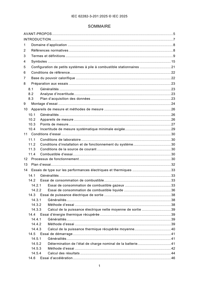
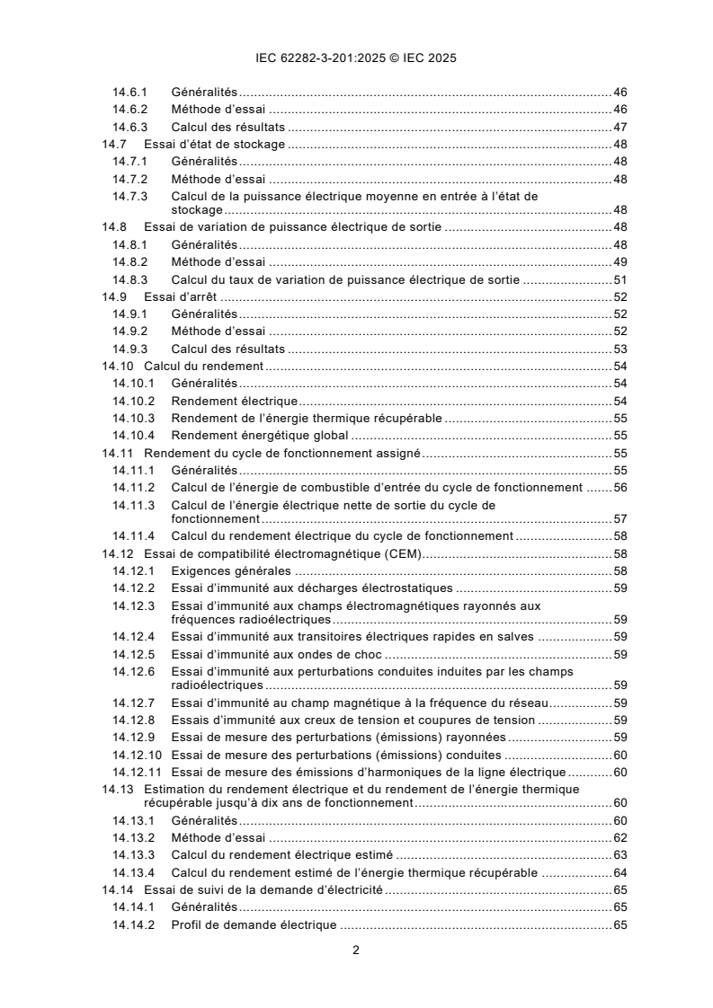
IEC 62282-3-201:2025 - Technologies des piles à combustible - Partie 3-201: Systèmes à piles à combustible stationnaires - Méthodes d'essai des performances pour petits systèmes à piles à combustible/25/2025
IEC 62282-3-201:2025 - Fuel cell technologies - Part 3-201: Stationary fuel cell power systems - Performance test methods for small fuel cell power systems/25/2025
Overview
IEC 62282-3-201:2025 - "Fuel cell technologies - Part 3-201: Stationary fuel cell power systems - Performance test methods for small fuel cell power systems" defines laboratory type test methods for evaluating the electrical, thermal and environmental performance of small stationary fuel cell power systems. It applies to systems with a rated electric output < 10 kW, single- or three-phase AC (≤ 1 000 V) or DC (≤ 1 500 V) output, fuel/oxidant passages rated ≤ 0.1 MPa (gauge), gaseous or liquid fuels (natural gas, LPG, hydrogen, kerosene, methanol, etc.) and air as oxidant. This third edition (2025) replaces the 2017 edition and Amendment 1:2022 and updates terminology, measurement requirements, test conditions and multiple test procedures.
Key Topics and Requirements
- Scope limits: small stationary fuel cell power systems intended primarily for electricity production (heat recovery optional).
- Type tests only: the standard specifies test methods under laboratory conditions; it does not set performance targets or routine test requirements.
- Measurement & uncertainty: updated requirements for measurement instruments and minimum systematic uncertainty.
- Test regimes (selected):
- Fuel consumption (gaseous and liquid fuels)
- Electric power output and net power calculations
- Heat recovery and recovered thermal power measurement
- Start-up, ramp-up, shutdown, storage and demand-following tests
- Efficiency computations (electrical, heat recovery, overall) and estimated performance up to 10 years
- Environmental tests: noise, exhaust gas composition, discharge water
- Electromagnetic compatibility (EMC) and emissions tests
- Test preparation: reference conditions, data acquisition plans, test set-ups and instrumentation points are defined.
- Reporting: structured test report content and annex guidance (heating values, gas compositions, example schedules).
Applications and Who Uses It
- Manufacturers of small stationary fuel cell systems for product development and design verification.
- Test laboratories and certification bodies performing type testing, performance verification and compliance assessment.
- R&D teams and integrators evaluating fuel consumption, heat recovery potential and long-term efficiency estimates.
- System specifiers, energy consultants and utilities assessing suitability of small fuel cell systems for micro-generation, CHP (combined heat and power) and backup power applications.
- Useful when documenting performance for procurement, certification, product datasheets and regulatory submissions.
Related Standards
- Other parts of the IEC 62282 fuel cell technologies family (for complementary safety, interfaces and system aspects).
- Relevant EMC standards (e.g., IEC 61000 series) for detailed electromagnetic immunity/emission requirements.
Keywords: IEC 62282-3-201:2025, fuel cell performance tests, small stationary fuel cell, type tests, heat recovery, fuel consumption, EMC testing, exhaust emissions, noise testing, <10 kW systems.
Relations
- Effective Date
- 05-Sep-2023
- Effective Date
- 05-Sep-2023
Buy Documents
IEC 62282-3-201:2025 - Fuel cell technologies - Part 3-201: Stationary fuel cell power systems - Performance test methods for small fuel cell power systems/25/2025
IEC 62282-3-201:2025 RLV - Fuel cell technologies - Part 3-201: Stationary fuel cell power systems - Performance test methods for small fuel cell power systems Released:9/25/2025
IEC 62282-3-201:2025 - Technologies des piles à combustible - Partie 3-201: Systèmes à piles à combustible stationnaires - Méthodes d'essai des performances pour petits systèmes à piles à combustible/25/2025
IEC 62282-3-201:2025 - Fuel cell technologies - Part 3-201: Stationary fuel cell power systems - Performance test methods for small fuel cell power systems/25/2025
Get Certified
Connect with accredited certification bodies for this standard

DNV
DNV is an independent assurance and risk management provider.

Lloyd's Register
Lloyd's Register is a global professional services organisation specialising in engineering and technology.
DNV Energy Systems
Energy and renewable energy certification.
Sponsored listings
Frequently Asked Questions
IEC 62282-3-201:2025 is a standard published by the International Electrotechnical Commission (IEC). Its full title is "Fuel cell technologies - Part 3-201: Stationary fuel cell power systems - Performance test methods for small fuel cell power systems". This standard covers: IEC 62282-3-201:2025 provides test methods for the electrical, thermal, and environmental performance of small stationary fuel cell power systems that meet the following criteria: - output: rated electric power output of less than 10 kW; - output mode: grid-connected/independent operation or stand-alone operation with single-phase AC output or 3-phase AC output not exceeding 1 000 V, or DC output not exceeding 1 500 V; - operating pressure: maximum allowable working pressure of 0,1 MPa (gauge) for the fuel and oxidant passages; - fuel: gaseous fuel (natural gas, liquefied petroleum gas, propane, butane, hydrogen, etc.) or liquid fuel (kerosene, methanol, etc.); - oxidant: air. This document describes type tests and their test methods only. No routine tests are required or identified, and no performance targets are set in this document. This document provides test methods to be carried out under laboratory conditions. This document covers fuel cell power systems whose primary purpose is the production of electric power and whose secondary purpose can be the utilization of heat. Accordingly, fuel cell power systems for which the use of heat is primary, and the use of electric power is secondary are outside the scope of this document. This third edition cancels and replaces the second edition published in 2017 and Amendment 1:2022. This edition includes the following significant technical changes with respect to the previous edition: - revision of Introduction; - revision of terms and definitions; - revision of Table 1; - revision of Figure 1, Figure 2, Figure 3 and Figure 4; - revision of measurement instruments (10.2); - revision of minimum required measurement systematic uncertainty (10.4); - revision of test conditions (Clause 11); - revision of operating process (Clause 12); - revision of fuel consumption test (14.2); - revision of heat recovery test (14.4); - revision of Figure 13 and Figure 14; - revision of calculation of results (14.14.4); - revision of Annex A and Annex B.
IEC 62282-3-201:2025 provides test methods for the electrical, thermal, and environmental performance of small stationary fuel cell power systems that meet the following criteria: - output: rated electric power output of less than 10 kW; - output mode: grid-connected/independent operation or stand-alone operation with single-phase AC output or 3-phase AC output not exceeding 1 000 V, or DC output not exceeding 1 500 V; - operating pressure: maximum allowable working pressure of 0,1 MPa (gauge) for the fuel and oxidant passages; - fuel: gaseous fuel (natural gas, liquefied petroleum gas, propane, butane, hydrogen, etc.) or liquid fuel (kerosene, methanol, etc.); - oxidant: air. This document describes type tests and their test methods only. No routine tests are required or identified, and no performance targets are set in this document. This document provides test methods to be carried out under laboratory conditions. This document covers fuel cell power systems whose primary purpose is the production of electric power and whose secondary purpose can be the utilization of heat. Accordingly, fuel cell power systems for which the use of heat is primary, and the use of electric power is secondary are outside the scope of this document. This third edition cancels and replaces the second edition published in 2017 and Amendment 1:2022. This edition includes the following significant technical changes with respect to the previous edition: - revision of Introduction; - revision of terms and definitions; - revision of Table 1; - revision of Figure 1, Figure 2, Figure 3 and Figure 4; - revision of measurement instruments (10.2); - revision of minimum required measurement systematic uncertainty (10.4); - revision of test conditions (Clause 11); - revision of operating process (Clause 12); - revision of fuel consumption test (14.2); - revision of heat recovery test (14.4); - revision of Figure 13 and Figure 14; - revision of calculation of results (14.14.4); - revision of Annex A and Annex B.
IEC 62282-3-201:2025 is classified under the following ICS (International Classification for Standards) categories: 27.070 - Fuel cells. The ICS classification helps identify the subject area and facilitates finding related standards.
IEC 62282-3-201:2025 has the following relationships with other standards: It is inter standard links to IEC 62282-3-201:2017/AMD1:2022, IEC 62282-3-201:2017. Understanding these relationships helps ensure you are using the most current and applicable version of the standard.
IEC 62282-3-201:2025 is available in PDF format for immediate download after purchase. The document can be added to your cart and obtained through the secure checkout process. Digital delivery ensures instant access to the complete standard document.
Standards Content (Sample)
IEC 62282-3-201 ®
Edition 3.0 2025-09
INTERNATIONAL
STANDARD
Fuel cell technologies -
Part 3-201: Stationary fuel cell power systems - Performance test methods for
small fuel cell power systems
ICS 27.070 ISBN 978-2-8327-0637-4
All rights reserved. Unless otherwise specified, no part of this publication may be reproduced or utilized in any form or
by any means, electronic or mechanical, including photocopying and microfilm, without permission in writing from either
IEC or IEC's member National Committee in the country of the requester. If you have any questions about IEC copyright
or have an enquiry about obtaining additional rights to this publication, please contact the address below or your local
IEC member National Committee for further information.
IEC Secretariat Tel.: +41 22 919 02 11
3, rue de Varembé info@iec.ch
CH-1211 Geneva 20 www.iec.ch
Switzerland
About the IEC
The International Electrotechnical Commission (IEC) is the leading global organization that prepares and publishes
International Standards for all electrical, electronic and related technologies.
About IEC publications
The technical content of IEC publications is kept under constant review by the IEC. Please make sure that you have the
latest edition, a corrigendum or an amendment might have been published.
IEC publications search - IEC Products & Services Portal - products.iec.ch
webstore.iec.ch/advsearchform Discover our powerful search engine and read freely all the
The advanced search enables to find IEC publications by a publications previews, graphical symbols and the glossary.
variety of criteria (reference number, text, technical With a subscription you will always have access to up to date
committee, …). It also gives information on projects, content tailored to your needs.
replaced and withdrawn publications.
Electropedia - www.electropedia.org
The world's leading online dictionary on electrotechnology,
IEC Just Published - webstore.iec.ch/justpublished
Stay up to date on all new IEC publications. Just Published containing more than 22 500 terminological entries in English
details all new publications released. Available online and and French, with equivalent terms in 25 additional languages.
once a month by email. Also known as the International Electrotechnical Vocabulary
(IEV) online.
IEC Customer Service Centre - webstore.iec.ch/csc
If you wish to give us your feedback on this publication or
need further assistance, please contact the Customer
Service Centre: sales@iec.ch.
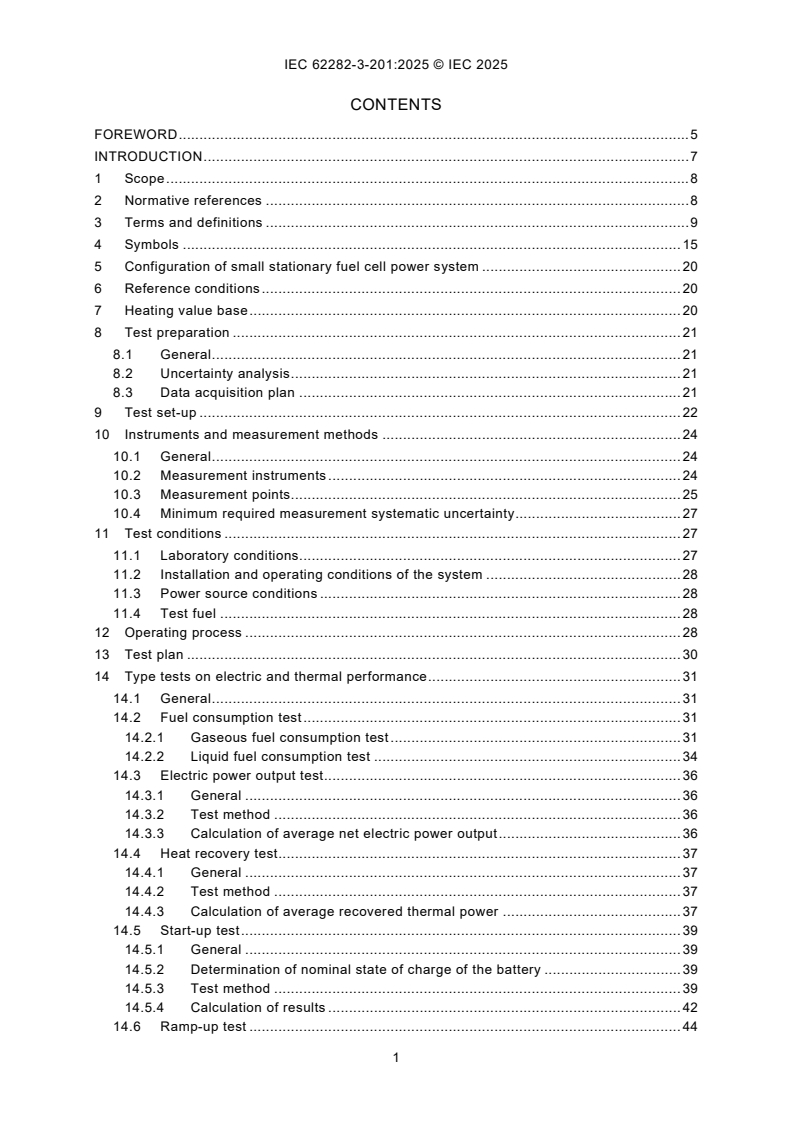
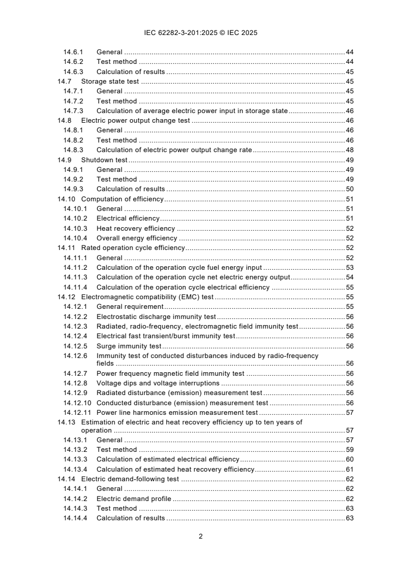
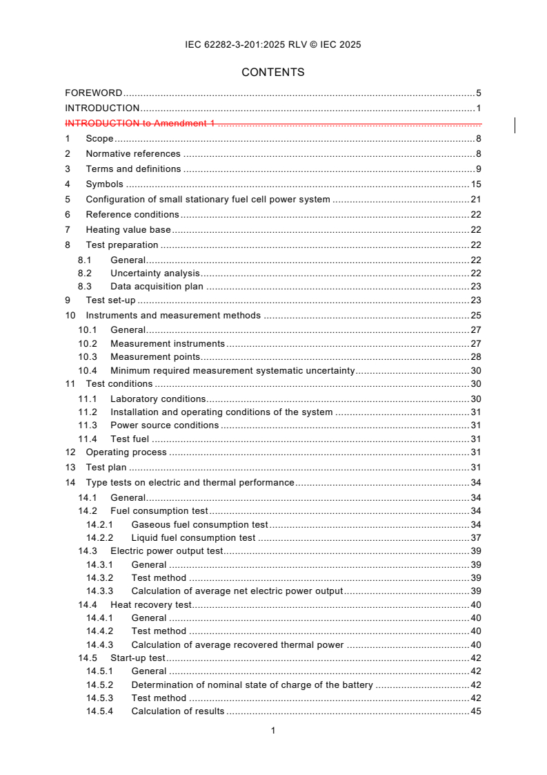
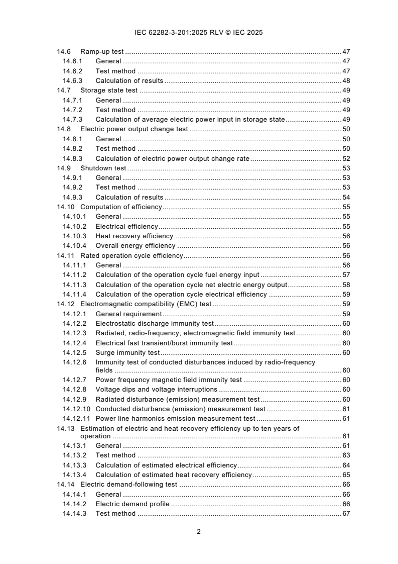
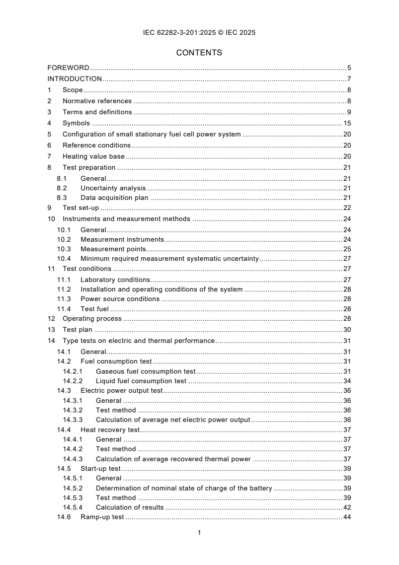
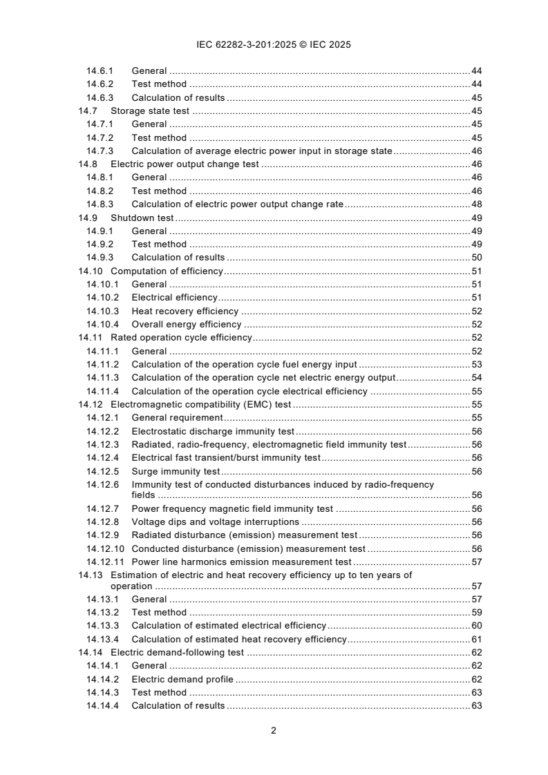
CONTENTS
FOREWORD . 5
INTRODUCTION . 7
1 Scope . 8
2 Normative references . 8
3 Terms and definitions . 9
4 Symbols . 15
5 Configuration of small stationary fuel cell power system . 20
6 Reference conditions . 20
7 Heating value base . 20
8 Test preparation . 21
8.1 General . 21
8.2 Uncertainty analysis . 21
8.3 Data acquisition plan . 21
9 Test set-up . 22
10 Instruments and measurement methods . 24
10.1 General . 24
10.2 Measurement instruments . 24
10.3 Measurement points. 25
10.4 Minimum required measurement systematic uncertainty . 27
11 Test conditions . 27
11.1 Laboratory conditions. 27
11.2 Installation and operating conditions of the system . 28
11.3 Power source conditions . 28
11.4 Test fuel . 28
12 Operating process . 28
13 Test plan . 30
14 Type tests on electric and thermal performance . 31
14.1 General . 31
14.2 Fuel consumption test . 31
14.2.1 Gaseous fuel consumption test . 31
14.2.2 Liquid fuel consumption test . 34
14.3 Electric power output test . 36
14.3.1 General . 36
14.3.2 Test method . 36
14.3.3 Calculation of average net electric power output . 36
14.4 Heat recovery test . 37
14.4.1 General . 37
14.4.2 Test method . 37
14.4.3 Calculation of average recovered thermal power . 37
14.5 Start-up test . 39
14.5.1 General . 39
14.5.2 Determination of nominal state of charge of the battery . 39
14.5.3 Test method . 39
14.5.4 Calculation of results . 42
14.6 Ramp-up test . 44
14.6.1 General . 44
14.6.2 Test method . 44
14.6.3 Calculation of results . 45
14.7 Storage state test . 45
14.7.1 General . 45
14.7.2 Test method . 45
14.7.3 Calculation of average electric power input in storage state . 46
14.8 Electric power output change test . 46
14.8.1 General . 46
14.8.2 Test method . 46
14.8.3 Calculation of electric power output change rate . 48
14.9 Shutdown test . 49
14.9.1 General . 49
14.9.2 Test method . 49
14.9.3 Calculation of results . 50
14.10 Computation of efficiency . 51
14.10.1 General . 51
14.10.2 Electrical efficiency . 51
14.10.3 Heat recovery efficiency . 52
14.10.4 Overall energy efficiency . 52
14.11 Rated operation cycle efficiency. 52
14.11.1 General . 52
14.11.2 Calculation of the operation cycle fuel energy input . 53
14.11.3 Calculation of the operation cycle net electric energy output . 54
14.11.4 Calculation of the operation cycle electrical efficiency . 55
14.12 Electromagnetic compatibility (EMC) test . 55
14.12.1 General requirement . 55
14.12.2 Electrostatic discharge immunity test . 56
14.12.3 Radiated, radio-frequency, electromagnetic field immunity test . 56
14.12.4 Electrical fast transient/burst immunity test . 56
14.12.5 Surge immunity test . 56
14.12.6 Immunity test of conducted disturbances induced by radio-frequency
fields . 56
14.12.7 Power frequency magnetic field immunity test . 56
14.12.8 Voltage dips and voltage interruptions . 56
14.12.9 Radiated disturbance (emission) measurement test . 56
14.12.10 Conducted disturbance (emission) measurement test . 56
14.12.11 Power line harmonics emission measurement test . 57
14.13 Estimation of electric and heat recovery efficiency up to ten years of
operation . 57
14.13.1 General . 57
14.13.2 Test method . 59
14.13.3 Calculation of estimated electrical efficiency . 60
14.13.4 Calculation of estimated heat recovery efficiency . 61
14.14 Electric demand-following test . 62
14.14.1 General . 62
14.14.2 Electric demand profile . 62
14.14.3 Test method . 63
14.14.4 Calculation of results . 63
14.14.5 Calculation of efficiencies . 65
15 Type tests on environmental performance . 65
15.1 General . 65
15.2 Noise test . 65
15.2.1 General . 65
15.2.2 Test conditions . 65
15.2.3 Test method . 66
15.2.4 Processing of data . 67
15.3 Exhaust gas test . 67
15.3.1 General . 67
15.3.2 Components to be measured . 67
15.3.3 Test method . 68
15.3.4 Processing of data . 70
15.4 Discharge water test . 81
15.4.1 General . 81
15.4.2 Test method . 81
16 Test reports . 82
16.1 General . 82
16.2 Title page. 82
16.3 Table of contents . 82
16.4 Summary report . 82
Annex A (normative) Heating values for components of natural gas . 83
Annex B (informative) Examples of compositions for natural gas and propane gas . 85
Annex C (informative) Example of a test operation schedule . 87
Annex D (informative) Typical exhaust gas components . 88
Annex E (informative) Guidelines for the contents of detailed and full reports . 89
E.1 General . 89
E.2 Detailed report . 89
E.3 Full report . 89
Annex F (informative) Selected duration of rated power operation . 90
Bibliography . 91
Figure 1 – Symbol diagram . 18
Figure 2 – General configuration of small stationary fuel cell power system . 20
Figure 3 – Test set-up for small stationary fuel cell power system fed with gaseous fuel
which supplies electricity and useful heat. 23
Figure 4 – Test set-up for small stationary fuel cell power system fed with gaseous fuel
which supplies only electricity . 24
Figure 5 – Operating states of stationary fuel cell power system without battery . 29
Figure 6 – Operating states of stationary fuel cell power system with battery . 30
Figure 7 – Example of electric power chart during start-up time for system without
battery . 40
Figure 8 – Example of electric power chart during start-up time for system with battery . 41
Figure 9 – Example of liquid fuel supply systems . 42
Figure 10 – Example of electric power chart during ramp-up for system without battery . 44
Figure 11 – Electric power output change pattern for system without battery . 47
Figure 12 – Electric power output change pattern for system with battery . 47
Figure 13 – Guideline to attain steady state . 48
Figure 14 – Electric power chart during shutdown time . 50
Figure 15 – Example of electrical efficiency during ten years of operation . 58
Figure 16 – Example of the electric demand of a residential application . 62
Figure 17 – Noise measurement points for small stationary fuel cell power systems . 66
Figure 18 – Example of combustion exhaust gas collectors and collection locations . 69
Table 1 – Symbols and their meanings for electric and thermal performance . 15
Table 2 – Additional symbols and their meanings for environmental performance . 18
Table 3 – Compensation of readings against the effect of background noise . 66
Table A.1 – Heating values for components of natural gas at reference temperature
(288,15 K) on molar and mass basis for ideal gas . 83
Table B.1 – Example of compositions for natural gas (%) . 85
Table B.2 – Example of compositions for propane gas (%) . 86
Table C.1 – Example of a test operation schedule . 87
Table D.1 – Typical exhaust gas components to be expected for typical fuels . 88
Table F.1 – Selected duration of rated power operation . 90
INTERNATIONAL ELECTROTECHNICAL COMMISSION
____________
Fuel cell technologies -
Part 3-201: Stationary fuel cell power systems -
Performance test methods for small fuel cell power systems
FOREWORD
1) The International Electrotechnical Commission (IEC) is a worldwide organization for standardization comprising
all national electrotechnical committees (IEC National Committees). The object of IEC is to promote international
co-operation on all questions concerning standardization in the electrical and electronic fields. To this end and
in addition to other activities, IEC publishes International Standards, Technical Specifications, Technical Reports,
Publicly Available Specifications (PAS) and Guides (hereafter referred to as "IEC Publication(s)"). Their
preparation is entrusted to technical committees; any IEC National Committee interested in the subject dealt with
may participate in this preparatory work. International, governmental and non-governmental organizations liaising
with the IEC also participate in this preparation. IEC collaborates closely with the International Organization for
Standardization (ISO) in accordance with conditions determined by agreement between the two organizations.
2) The formal decisions or agreements of IEC on technical matters express, as nearly as possible, an international
consensus of opinion on the relevant subjects since each technical committee has representation from all
interested IEC National Committees.
3) IEC Publications have the form of recommendations for international use and are accepted by IEC National
Committees in that sense. While all reasonable efforts are made to ensure that the technical content of IEC
Publications is accurate, IEC cannot be held responsible for the way in which they are used or for any
misinterpretation by any end user.
4) In order to promote international uniformity, IEC National Committees undertake to apply IEC Publications
transparently to the maximum extent possible in their national and regional publications. Any divergence between
any IEC Publication and the corresponding national or regional publication shall be clearly indicated in the latter.
5) IEC itself does not provide any attestation of conformity. Independent certification bodies provide conformity
assessment services and, in some areas, access to IEC marks of conformity. IEC is not responsible for any
services carried out by independent certification bodies.
6) All users should ensure that they have the latest edition of this publication.
7) No liability shall attach to IEC or its directors, employees, servants or agents including individual experts and
members of its technical committees and IEC National Committees for any personal injury, property damage or
other damage of any nature whatsoever, whether direct or indirect, or for costs (including legal fees) and
expenses arising out of the publication, use of, or reliance upon, this IEC Publication or any other IEC
Publications.
8) Attention is drawn to the Normative references cited in this publication. Use of the referenced publications is
indispensable for the correct application of this publication.
9) IEC draws attention to the possibility that the implementation of this document may involve the use of (a)
patent(s). IEC takes no position concerning the evidence, validity or applicability of any claimed patent rights in
respect thereof. As of the date of publication of this document, IEC had not received notice of (a) patent(s), which
may be required to implement this document. However, implementers are cautioned that this may not represent
the latest information, which may be obtained from the patent database available at https://patents.iec.ch. IEC
shall not be held responsible for identifying any or all such patent rights.
IEC 62282-3-201 has been prepared by IEC technical committee 105: Fuel cell technologies. It
is an International Standard.
This third edition cancels and replaces the second edition published in 2017 and
Amendment 1:2022. This edition constitutes a technical revision.
This edition includes the following significant technical changes with respect to the previous
edition:
a) revision of Introduction;
b) revision of terms and definitions;
c) revision of Table 1;
d) revision of Figure 1, Figure 2, Figure 3 and Figure 4;
e) revision of measurement instruments (10.2);
f) revision of minimum required measurement systematic uncertainty (10.4);
g) revision of test conditions (Clause 11);
h) revision of operating process (Clause 12);
i) revision of fuel consumption test (14.2);
j) revision of heat recovery test (14.4);
k) revision of Figure 13 and Figure 14;
l) revision of calculation of results (14.14.4);
m) revision of Annex A and Annex B.
The text of this International Standard is based on the following documents:
Draft Report on voting
105/1114/FDIS 105/1128/RVD
Full information on the voting for its approval can be found in the report on voting indicated in
the above table.
The language used for the development of this International Standard is English.
This document was drafted in accordance with ISO/IEC Directives, Part 2, and developed in
accordance with ISO/IEC Directives, Part 1 and ISO/IEC Directives, IEC Supplement, available
at www.iec.ch/members_experts/refdocs. The main document types developed by IEC are
described in greater detail at www.iec.ch/publications.
A list of all parts in the IEC 62282 series, published under the general title Fuel cell technologies,
can be found on the IEC website.
The committee has decided that the contents of this document will remain unchanged until the
stability date indicated on the IEC website under webstore.iec.ch in the data related to the
specific document. At this date, the document will be
• reconfirmed,
• withdrawn, or
• revised.
INTRODUCTION
This part of IEC 62282 provides consistent and repeatable test methods for the electrical,
thermal and environmental performance of small stationary fuel cell power systems.
This document limits its scope to small stationary fuel cell power systems (electrical power
output below 10 kW, which is typical for residential, small commercial and off-grid applications)
and provides test methods specifically designed for them in detail. It is based on the latest
edition of IEC 62282-3-200, which generally describes performance test methods that are
common to all types of fuel cells.
This document is intended for manufacturers of small stationary fuel cell power systems or
those who evaluate the performance of their systems for certification purposes, or both.
Users of this document can selectively execute test items that are suitable for their purposes
from those described in this document. This document is not intended to exclude any other
methods.
1 Scope
This part of IEC 62282 provides test methods for the electrical, thermal, and environmental
performance of small stationary fuel cell power systems that meet the following criteria:
• output: rated electric power output of less than 10 kW;
• output mode: grid-connected/independent operation or stand-alone operation with single-
phase AC output or 3-phase AC output not exceeding 1 000 V, or DC output not exceeding
1 500 V;
NOTE The limit of 1 000 V for alternating current comes from the definition for "low voltage" given in
IEC 60050-601:1985, 601-01-26.
• operating pressure: maximum allowable working pressure of 0,1 MPa (gauge) for the fuel
and oxidant passages;
• fuel: gaseous fuel (natural gas, liquefied petroleum gas, propane, butane, hydrogen, etc.)
or liquid fuel (kerosene, methanol, etc.);
• oxidant: air.
This document describes type tests and their test methods only. No routine tests are required
or identified, and no performance targets are set in this document.
This document provides test methods to be carried out under laboratory conditions.
This document covers fuel cell power systems whose primary purpose is the production of
electric power and whose secondary purpose can be the utilization of heat. Accordingly, fuel
cell power systems for which the use of heat is primary, and the use of electric power is
secondary are outside the scope of this document.
All systems with integrated batteries are covered by this document. This includes systems
where batteries are recharged internally or recharged from an external source.
This document does not cover additional auxiliary heat generators that produce thermal energy.
2 Normative references
The following documents are referred to in the text in such a way that some or all of their content
constitutes requirements of this document. For dated references, only the edition cited applies.
For undated references, the latest edition of the referenced document (including any
amendments) applies.
CISPR 11, Industrial, scientific, and medical equipment - Radio-frequency disturbance
characteristics - Limits and methods of measurement
IEC 61000-3-2, Electromagnetic compatibility (EMC) - Part 3-2: Limits - Limits for harmonic
current emissions (equipment input current ≤ 16 A per phase)
IEC 61000-4-2, Electromagnetic compatibility (EMC) - Part 4-2: Testing and measurement
techniques - Electrostatic discharge immunity test
IEC 61000-4-3, Electromagnetic compatibility (EMC) - Part 4-3: Testing and measurement
techniques - Radiated, radio-frequency, electromagnetic field immunity test
IEC 61000-4-4, Electromagnetic compatibility (EMC) - Part 4-4: Testing and measurement
techniques - Electrical fast transient/burst immunity test
IEC 61000-4-5, Electromagnetic compatibility (EMC) - Part 4-5: Testing and measurement
techniques - Surge immunity test
IEC 61000-4-6, Electromagnetic compatibility (EMC) - Part 4-6: Testing and measurement
techniques - Immunity to conducted disturbances, induced by radio-frequency fields
IEC 61000-4-8, Electromagnetic compatibility (EMC) - Part 4-8: Testing and measurement
techniques - Power frequency magnetic field immunity test
IEC 61000-4-11, Electromagnetic compatibility (EMC) - Part 4-11: Testing and measurement
techniques - Voltage dips, short interruptions and voltage variations immunity tests for
equipment with input current up to 16 A per phase
IEC 61000-6-1:2016, Electromagnetic compatibility (EMC) - Part 6-1: Generic standards -
Immunity for residential, commercial and light-industrial environments
3 Terms and definitions
For the purposes of this document, the following terms and definitions apply.
ISO and IEC maintain terminology databases for use in standardization at the following
addresses:
• IEC Electropedia: available at https://www.electropedia.org/
• ISO Online browsing platform: available at https://www.iso.org/obp
3.1
background noise level
sound pressure level of ambient noise at the measurement point
Note 1 to entry: This measurement is taken as described in 15.2 with the fuel cell power system in the cold state.
3.2
battery
electrochemical energy storage device that provides energy input to auxiliary machines and
equipment necessary to operate the fuel cell power system and/or provides electric energy
output
Note 1 to entry: Back-up batteries for control software memory and similar applications are not included.
3.3
cold state
state of a fuel cell power system, which is entirely at ambient temperature with no power input
or output, ready for start-up
Note 1 to entry: Power input to a control device for monitoring the fuel cell power system during cold state is not
considered.
[SOURCE: IEC 60050-485:2020, 485-21-01, modified – "which is entirely" and "ready for start-
up" added; Note 1 to entry added.]
3.4
degradation rate
reduction of the electrical efficiency of a stationary fuel cell power system per time of operation
Note 1 to entry: The degradation rate is expressed in efficiency per cent points per time (%/h).
3.5
discharge water
water that is discharged from the fuel cell power system including waste water and condensate
Note 1 to entry: Discharge water does not constitute part of a thermal recovery system.
3.6
electrical efficiency
ratio of the average net electric power output produced by a fuel cell power system to the
average fuel power input supplied to the fuel cell power system
Note 1 to entry: Lower heating value (LHV) is assumed unless otherwise stated.
Note 2 to entry: Only the fuel energy is considered as input power to small fuel cell power systems.
[SOURCE: IEC 60050-485:2020, 485-10-02, modified – "electrical" instead of "electric" in the
term;" average net electric power output" instead of "net electric power"; "average fuel power
input" instead of "total enthalpy flow" and Note 2 to entry added.]
3.7
electric energy input
integrated value of electric power input at the electric input terminal
3.8
electric energy output
integrated value of electric power output at the electric output terminal
3.9
electric power input
electric power input at the electric input terminal of the fuel cell power system
3.10
electric power output
electric power output at the electric output terminal of the fuel cell power system
3.11
fuel cell power system
generator system that uses one or more fuel cell modules to generate electric power and heat
[SOURCE: IEC 60050-485:2020, 485-09-01]
3.12
fuel energy input
amount of chemical energy which is supplied to the fuel cell power system by the fuel
3.13
fuel input
amount of natural gas, hydrogen, methanol, liquid petroleum gas, propane, butane, or other
material containing chemical energy entering the fuel cell power system while it is working at
the specified operating conditions
3.14
fuel power input
fuel energy input per unit of time
3.15
heat recovery efficiency
ratio of the average recovered thermal power output of a fuel cell power system to the average
fuel power input supplied to the fuel cell power system
Note 1 to entry: Lower heating value (LHV) is assumed unless otherwise stated.
Note 2 to entry: Only the fuel energy is considered as input power to small fuel cell power systems.
[SOURCE: IEC 60050-485:2020, 485-10-04, modified – "average recovered thermal power
output" instead of "recovered heat flow"; "average total power input" instead of "total enthalpy
flow"; Note 1 to entry deleted, new Note 1 to entry and Note 2 to entry added.]
3.16
heat recovery fluid
fluid circulating between the fuel cell power system and a heat sink for recovering the thermal
energy output
3.17
inert purge gas
inert gas or dilution gas, not containing chemical energy, supplied to the fuel cell power system
during specific conditions to make it ready for operation or shutdown
Note 1 to entry: Dilution gas containing chemical energy shall be considered as fuel.
3.18
integrated fuel input
volume or mass of fuel consumed by the fuel cell power system under specified operating
conditions
3.19
interface point
measurement point at the boundary of a fuel cell power system at which material or energy, or
both, either enters or leaves
Note 1 to entry: This boundary is intentionally selected to accurately measure the performance of the system,
including all normal operation, both steady state and transient. If necessary, the boundary or the interface points of
the fuel cell power system (Figure 2) to be assessed should be determined by agreement between the parties.
[SOURCE: IEC 60050-485:2020, 485-09-12, modified – Note 2 to entry deleted.]
3.20
mass concentration
concentration of mass of exhaust gas component per unit of volume
3.21
mass discharge rate
mass of discharged exhaust gas component per unit of time
3.22
minimum electric power output
minimum net power output, at which a fuel cell power system is able to operate continuously at
a steady state
3.23
net electric power output
power generated by the fuel cell power system and available for external use
Note 1 to entry: The net electric power output can be negative during start-up, shutdown and storage state, which
means actually an electric power input during these phases / state, to be provided externally and not generated by
the fuel cell power system.
[SOURCE: IEC 60050-485:2020, 485-14-03, modified – "output" added to the term, Notes 1
and 2 to entry deleted, and new Note 1 to entry added.]
3.24
noise level
sound pressure level produced by the fuel cell power system
Note 1 to entry: The noise level is expressed as decibels (dB) and measured as described in 15.2.
3.25
operation cycle
complete sequence of successive operation phases of a fuel cell power system comprising
start-up, ramp-up, rated operation and shutdown
3.26
operation cycle electrical efficiency
ratio of the net electric energy output of a fuel cell power system to the fuel energy fed to the
same fuel cell power system during a complete operation cycle comprising start-up, ramp-up,
rated operation and shutdown
3.27
overall energy efficiency
ratio of total usable power output (net electric power and recovered thermal power) to the
average total power input supplied to the fuel cell power system
Note 1 to entry: For determining the total power input to small fuel cell power systems, power inputs other than fuel
power input are neglected as insignificant
[SOURCE: IEC 60050-485:2020, 485-10-05, modified – alternative expression "or total thermal
efficiency" deleted; "power output" instead of "energy flow"; "thermal power" instead of "heat
flow"; "average total power input" instead of "total enthalpy flow"; Note 1 to entry changed.]
3.28
pre-generation state
state of a fuel cell power system at sufficient operating temperature and in such an operational
mode, with zero electric power output, that the fuel cell power system is capable of being
promptly switched to an operational state with a substantial electric active power output
[SOURCE: IEC 60050-485:2020, 485-21-04, modified – "active" added.]
3.29
ramp-up energy
electric and/or chemical (fuel) energy required for transitioning from positive net electric power
output after start-up to rated net electric power output
3.30
ramp-up time
duration required for transitioning from positive net electric power output after start-up to rated
net electric power output
3.31
rated electric power output
maximum continuous electric power output that a fuel cell power system is designed to achieve
under normal operating conditions specified by the manufacturer
[SOURCE: IEC 60050-485:2020, 485-14-04, modified – "electric" and "output" added to the
term, Note 1 to entry deleted.]
3.32
recovered heat
thermal energy that has been recovered for useful purpose
3.33
recovered thermal power
recovered heat per unit of time
Note 1 to entry: The recovered thermal power is measured by determining the temperatures and flow rates of the
heat recovery fluid (water, steam, air or oil, etc.) entering and leaving the thermal energy recovery subsystem at the
interface point of the fuel cell power system.
3.34
shutdown energy
sum of electric and/or chemical (fuel) energy required during the shutdown time
3.35
shutdown time
duration between the instant when a shutdown action is initiated at rated electric power output
and the instant when the shutdown is completed, as specified by the manufacturer
Note 1 to entry: The shutdown operation is classified into types: normal shutdown and emergency shutdown.
[SOURCE: IEC 60050-485:2020, 485-20-04, modified – "a shutdown action is initiated at rated
electric power output" instead of "the load is removed"; "Note 1 to entry" added.]
3.36
start-up energy
sum of electric, thermal, mechanical and chemical
(fuel) energy required by a fuel cell power system for transitioning from cold state or storage
state to positive net electric power output
Note 1 to entry: The start-up process of fuel cell power systems without battery is shown in Figure 7.
[SOURCE: IEC 60050-485:2020, 485-18-05, modified – addition of domain, "for transitioning
from cold state or storage state to positive net electric power output" instead of "during the start
-up time" and Note 1 to entry added.]
3.37
start-up energy
sum of electric, thermal, mechanical and chemical (fuel)
energy required by a fuel cell power system for recharging the battery, which is discharged to
supply rated electric power output during start-up time, to a known nominal state of charge
Note 1 to entry: The start-up process of fuel cell power systems with battery is shown in Figure 8.
[SOURCE: IEC 60050-485:2020, 485-18-05, modified – addition of domain "for recharging the
battery, which is discharged to supply rated electric power output during start-up time, to a
known nominal state of chargefor transitioning from cold state or storage state to positive net
electric power output" instead of during the start -up time" and Note 1 to entry added.]
3.38
start-up time
duration required for transitioning from cold state to positive net electric power output
[SOURCE: IEC 60050-485:2020, 485-20-05, modified – "positive" added.]
3.39
start-up time
duration
required for transitioning from storage state to positive net electric power output
[SOURCE: IEC 60050-485:2020, 485-20-06, modified – "positive" added.]
3.40
stationary fuel cell power system
fuel cell power system that is connected and fixed in place
[SOURCE: IEC 60050-485:2020, 485-09-24]
3.41
steady state
state of a physical system in which the relevant characteristics remain constant with time
[SOURCE: IEC 60050-485:2020, 485-21-05]
3.42
storage state
state of a fuel cell power system being non-operational and possibly requiring, under conditions
specified by the manufacturer, the input of thermal energy, electric energy or an inert
atmosphere, or any combination thereof, in order to prevent deterioration of the components or
energize the control systems and other components, or both, and is ready for start-up
[SOURCE: IEC 60050-485:2020, 485-21-06, modified – "or energize the control systems and
other components, or both, and is ready for st
...
IEC 62282-3-201 ®
Edition 3.0 2025-09
INTERNATIONAL
STANDARD
REDLINE VERSION
Fuel cell technologies -
Part 3-201: Stationary fuel cell power systems - Performance test methods for
small fuel cell power systems
ICS 27.070 ISBN 978-2-8327-0749-4
All rights reserved. Unless otherwise specified, no part of this publication may be reproduced or utilized in any form or
by any means, electronic or mechanical, including photocopying and microfilm, without permission in writing from either
IEC or IEC's member National Committee in the country of the requester. If you have any questions about IEC copyright
or have an enquiry about obtaining additional rights to this publication, please contact the address below or your local
IEC member National Committee for further information.
IEC Secretariat Tel.: +41 22 919 02 11
3, rue de Varembé info@iec.ch
CH-1211 Geneva 20 www.iec.ch
Switzerland
About the IEC
The International Electrotechnical Commission (IEC) is the leading global organization that prepares and publishes
International Standards for all electrical, electronic and related technologies.
About IEC publications
The technical content of IEC publications is kept under constant review by the IEC. Please make sure that you have the
latest edition, a corrigendum or an amendment might have been published.
IEC publications search - IEC Products & Services Portal - products.iec.ch
webstore.iec.ch/advsearchform Discover our powerful search engine and read freely all the
The advanced search enables to find IEC publications by a publications previews, graphical symbols and the glossary.
variety of criteria (reference number, text, technical With a subscription you will always have access to up to date
committee, …). It also gives information on projects, content tailored to your needs.
replaced and withdrawn publications.
Electropedia - www.electropedia.org
The world's leading online dictionary on electrotechnology,
IEC Just Published - webstore.iec.ch/justpublished
Stay up to date on all new IEC publications. Just Published containing more than 22 500 terminological entries in English
details all new publications released. Available online and and French, with equivalent terms in 25 additional languages.
once a month by email. Also known as the International Electrotechnical Vocabulary
(IEV) online.
IEC Customer Service Centre - webstore.iec.ch/csc
If you wish to give us your feedback on this publication or
need further assistance, please contact the Customer
Service Centre: sales@iec.ch.
CONTENTS
FOREWORD . 5
INTRODUCTION . 1
INTRODUCTION to Amendment 1 .
1 Scope . 8
2 Normative references . 8
3 Terms and definitions . 9
4 Symbols . 15
5 Configuration of small stationary fuel cell power system . 21
6 Reference conditions . 22
7 Heating value base . 22
8 Test preparation . 22
8.1 General . 22
8.2 Uncertainty analysis . 22
8.3 Data acquisition plan . 23
9 Test set-up . 23
10 Instruments and measurement methods . 25
10.1 General . 27
10.2 Measurement instruments . 27
10.3 Measurement points. 28
10.4 Minimum required measurement systematic uncertainty . 30
11 Test conditions . 30
11.1 Laboratory conditions. 30
11.2 Installation and operating conditions of the system . 31
11.3 Power source conditions . 31
11.4 Test fuel . 31
12 Operating process . 31
13 Test plan . 31
14 Type tests on electric and thermal performance . 34
14.1 General . 34
14.2 Fuel consumption test . 34
14.2.1 Gaseous fuel consumption test . 34
14.2.2 Liquid fuel consumption test . 37
14.3 Electric power output test . 39
14.3.1 General . 39
14.3.2 Test method . 39
14.3.3 Calculation of average net electric power output . 39
14.4 Heat recovery test . 40
14.4.1 General . 40
14.4.2 Test method . 40
14.4.3 Calculation of average recovered thermal power . 40
14.5 Start-up test . 42
14.5.1 General . 42
14.5.2 Determination of nominal state of charge of the battery . 42
14.5.3 Test method . 42
14.5.4 Calculation of results . 45
14.6 Ramp-up test . 47
14.6.1 General . 47
14.6.2 Test method . 47
14.6.3 Calculation of results . 48
14.7 Storage state test . 49
14.7.1 General . 49
14.7.2 Test method . 49
14.7.3 Calculation of average electric power input in storage state . 49
14.8 Electric power output change test . 50
14.8.1 General . 50
14.8.2 Test method . 50
14.8.3 Calculation of electric power output change rate . 52
14.9 Shutdown test . 53
14.9.1 General . 53
14.9.2 Test method . 53
14.9.3 Calculation of results . 54
14.10 Computation of efficiency . 55
14.10.1 General . 55
14.10.2 Electrical efficiency . 55
14.10.3 Heat recovery efficiency . 56
14.10.4 Overall energy efficiency . 56
14.11 Rated operation cycle efficiency. 56
14.11.1 General . 56
14.11.2 Calculation of the operation cycle fuel energy input . 57
14.11.3 Calculation of the operation cycle net electric energy output . 58
14.11.4 Calculation of the operation cycle electrical efficiency . 59
14.12 Electromagnetic compatibility (EMC) test . 59
14.12.1 General requirement . 59
14.12.2 Electrostatic discharge immunity test . 60
14.12.3 Radiated, radio-frequency, electromagnetic field immunity test . 60
14.12.4 Electrical fast transient/burst immunity test . 60
14.12.5 Surge immunity test . 60
14.12.6 Immunity test of conducted disturbances induced by radio-frequency
fields . 60
14.12.7 Power frequency magnetic field immunity test . 60
14.12.8 Voltage dips and voltage interruptions . 60
14.12.9 Radiated disturbance (emission) measurement test . 60
14.12.10 Conducted disturbance (emission) measurement test . 61
14.12.11 Power line harmonics emission measurement test . 61
14.13 Estimation of electric and heat recovery efficiency up to ten years of
operation . 61
14.13.1 General . 61
14.13.2 Test method . 63
14.13.3 Calculation of estimated electrical efficiency . 64
14.13.4 Calculation of estimated heat recovery efficiency . 65
14.14 Electric demand-following test . 66
14.14.1 General . 66
14.14.2 Electric demand profile . 66
14.14.3 Test method . 67
14.14.4 Calculation of results . 67
14.14.5 Calculation of efficiencies . 69
15 Type tests on environmental performance . 69
15.1 General . 69
15.2 Noise test . 69
15.2.1 General . 69
15.2.2 Test conditions . 69
15.2.3 Test method . 70
15.2.4 Processing of data . 71
15.3 Exhaust gas test . 71
15.3.1 General . 71
15.3.2 Components to be measured . 71
15.3.3 Test method . 72
15.3.4 Processing of data . 74
15.4 Discharge water test . 85
15.4.1 General . 85
15.4.2 Test method . 85
16 Test reports . 86
16.1 General . 86
16.2 Title page. 86
16.3 Table of contents . 86
16.4 Summary report . 86
Annex A (normative) Heating values for components of natural gas . 87
Annex B (informative) Examples of compositions for natural gas and propane gas . 89
Annex C (informative) Example of a test operation schedule . 91
Annex D (informative) Typical exhaust gas components . 92
Annex E (informative) Guidelines for the contents of detailed and full reports . 93
E.1 General . 93
E.2 Detailed report . 93
E.3 Full report . 93
Annex F (informative) Selected duration of rated power operation . 94
Bibliography . 95
Figure 1 – Symbol diagram . 19
Figure 2 – General configuration of small stationary fuel cell power system . 21
Figure 3 – Test set-up for small stationary fuel cell power system fed with gaseous fuel
which supplies electricity and useful heat. 25
Figure 4 – Test set-up for small stationary fuel cell power system fed with gaseous fuel
which supplies only electricity . 27
Figure 5 – Operating states of stationary fuel cell power system without battery . 32
Figure 6 – Operating states of stationary fuel cell power system with battery . 33
Figure 7 – Example of electric power chart during start-up time for system without
battery . 43
Figure 8 – Example of electric power chart during start-up time for system with battery . 44
Figure 9 – Example of liquid fuel supply systems . 46
Figure 10 – Example of electric power chart during ramp-up for system without battery . 48
Figure 11 – Electric power output change pattern for system without battery . 51
Figure 12 – Electric power output change pattern for system with battery . 51
Figure 13 – Example for electric power change stabilization criteria Guideline to attain
steady state . 52
Figure 14 – Electric power chart during shutdown time . 54
Figure 15 – Example of electrical efficiency during ten years of operation . 62
Figure 16 – Example of the electric demand of a residential application . 66
Figure 17 – Noise measurement points for small stationary fuel cell power systems . 70
Figure 18 – Example of combustion exhaust gas collectors and collection locations . 73
Table 1 – Symbols and their meanings for electric and thermal performance . 15
Table 2 – Additional symbols and their meanings for environmental performance . 19
Table 3 – Compensation of readings against the effect of background noise . 70
Table A.1 – Heating values for components of natural gas at various combustion
reference conditions temperature (288,15 K) on molar and mass basis for ideal gas . 87
Table B.1 – Example of compositions for natural gas (%) . 89
Table B.2 – Example of compositions for propane gas (%) . 90
Table C.1 – Example of a test operation schedule . 91
Table D.1 – Typical exhaust gas components to be expected for typical fuels . 92
Table F.1 – Selected duration of rated power operation . 94
INTERNATIONAL ELECTROTECHNICAL COMMISSION
____________
Fuel cell technologies -
Part 3-201: Stationary fuel cell power systems -
Performance test methods for small fuel cell power systems
FOREWORD
1) The International Electrotechnical Commission (IEC) is a worldwide organization for standardization comprising
all national electrotechnical committees (IEC National Committees). The object of IEC is to promote international
co-operation on all questions concerning standardization in the electrical and electronic fields. To this end and
in addition to other activities, IEC publishes International Standards, Technical Specifications, Technical Reports,
Publicly Available Specifications (PAS) and Guides (hereafter referred to as "IEC Publication(s)"). Their
preparation is entrusted to technical committees; any IEC National Committee interested in the subject dealt with
may participate in this preparatory work. International, governmental and non-governmental organizations liaising
with the IEC also participate in this preparation. IEC collaborates closely with the International Organization for
Standardization (ISO) in accordance with conditions determined by agreement between the two organizations.
2) The formal decisions or agreements of IEC on technical matters express, as nearly as possible, an international
consensus of opinion on the relevant subjects since each technical committee has representation from all
interested IEC National Committees.
3) IEC Publications have the form of recommendations for international use and are accepted by IEC National
Committees in that sense. While all reasonable efforts are made to ensure that the technical content of IEC
Publications is accurate, IEC cannot be held responsible for the way in which they are used or for any
misinterpretation by any end user.
4) In order to promote international uniformity, IEC National Committees undertake to apply IEC Publications
transparently to the maximum extent possible in their national and regional publications. Any divergence between
any IEC Publication and the corresponding national or regional publication shall be clearly indicated in the latter.
5) IEC itself does not provide any attestation of conformity. Independent certification bodies provide conformity
assessment services and, in some areas, access to IEC marks of conformity. IEC is not responsible for any
services carried out by independent certification bodies.
6) All users should ensure that they have the latest edition of this publication.
7) No liability shall attach to IEC or its directors, employees, servants or agents including individual experts and
members of its technical committees and IEC National Committees for any personal injury, property damage or
other damage of any nature whatsoever, whether direct or indirect, or for costs (including legal fees) and
expenses arising out of the publication, use of, or reliance upon, this IEC Publication or any other IEC
Publications.
8) Attention is drawn to the Normative references cited in this publication. Use of the referenced publications is
indispensable for the correct application of this publication.
9) IEC draws attention to the possibility that the implementation of this document may involve the use of (a)
patent(s). IEC takes no position concerning the evidence, validity or applicability of any claimed patent rights in
respect thereof. As of the date of publication of this document, IEC had not received notice of (a) patent(s), which
may be required to implement this document. However, implementers are cautioned that this may not represent
the latest information, which may be obtained from the patent database available at https://patents.iec.ch. IEC
shall not be held responsible for identifying any or all such patent rights.
This redline version of the official IEC Standard allows the user to identify the changes made
to the previous edition IEC 62282-3-201:2017+AMD1:2022 CSV. A vertical bar appears in the
margin wherever a change has been made. Additions are in green text, deletions are in
strikethrough red text.
IEC 62282-3-201 has been prepared by IEC technical committee 105: Fuel cell technologies. It
is an International Standard.
This third edition cancels and replaces the second edition published in 2017 and
Amendment 1:2022. This edition constitutes a technical revision.
This edition includes the following significant technical changes with respect to the previous
edition:
a) revision of Introduction;
b) revision of terms and definitions;
c) revision of Table 1;
d) revision of Figure 1, Figure 2, Figure 3 and Figure 4;
e) revision of measurement instruments (10.2);
f) revision of minimum required measurement systematic uncertainty (10.4);
g) revision of test conditions (Clause 11);
h) revision of operating process (Clause 12);
i) revision of fuel consumption test (14.2);
j) revision of heat recovery test (14.4);
k) revision of Figure 13 and Figure 14;
l) revision of calculation of results (14.14.4);
m) revision of Annex A and Annex B.
The text of this International Standard is based on the following documents:
Draft Report on voting
105/1114/FDIS 105/1128/RVD
Full information on the voting for its approval can be found in the report on voting indicated in
the above table.
The language used for the development of this International Standard is English.
This document was drafted in accordance with ISO/IEC Directives, Part 2, and developed in
accordance with ISO/IEC Directives, Part 1 and ISO/IEC Directives, IEC Supplement, available
at www.iec.ch/members_experts/refdocs. The main document types developed by IEC are
described in greater detail at www.iec.ch/publications.
A list of all parts in the IEC 62282 series, published under the general title Fuel cell technologies,
can be found on the IEC website.
The committee has decided that the contents of this document will remain unchanged until the
stability date indicated on the IEC website under webstore.iec.ch in the data related to the
specific document. At this date, the document will be
• reconfirmed,
• withdrawn, or
• revised.
INTRODUCTION
This part of IEC 62282 provides consistent and repeatable test methods for the electrical,
thermal and environmental performance of small stationary fuel cell power systems.
This document limits its scope to small stationary fuel cell power systems (electrical power
output below 10 kW, which is typical for residential, small commercial and off-grid applications)
and provides test methods specifically designed for them in detail. It is based on the latest
edition of IEC 62282-3-200, which generally describes performance test methods that are
common to all types of fuel cells.
This document is intended for manufacturers of small stationary fuel cell power systems and/or
those who evaluate the performance of their systems for certification purposes, or both.
Users of this document may can selectively execute test items that are suitable for their
purposes from those described in this document. This document is not intended to exclude any
other methods.
INTRODUCTION to Amendment 1
This amendment to IEC 62282-3-201:2017 provides a method of estimating the electric and
heat recovery efficiency of small stationary fuel cell power systems for a duration of up to ten
years of operation. Furthermore, this amendment to IEC 62282-3-201:2017 provides an
evaluation method for electric demand-following small stationary fuel cell power systems, which
are operating at changing levels of power output. It has been developed as a reference for the
life cycle assessment calculations in IEC TS 62282-9-101.
1 Scope
This part of IEC 62282 provides test methods for the electrical, thermal, and environmental
performance of small stationary fuel cell power systems that meet the following criteria:
• output: rated electric power output of less than 10 kW;
• output mode: grid-connected/independent operation or stand-alone operation with single-
phase AC output or 3-phase AC output not exceeding 1 000 V, or DC output not exceeding
1 500 V;
NOTE The limit of 1 000 V for alternating current comes from the definition for "low voltage" given in
IEC 60050-601:1985, 601-01-26.
• operating pressure: maximum allowable working pressure of less than 0,1 MPa (gauge) for
the fuel and oxidant passages;
• fuel: gaseous fuel (natural gas, liquefied petroleum gas, propane, butane, hydrogen, etc.)
or liquid fuel (kerosene, methanol, etc.);
• oxidant: air.
This document describes type tests and their test methods only. No routine tests are required
or identified, and no performance targets are set in this document.
This document provides test methods to be carried out under laboratory conditions.
This document covers fuel cell power systems whose primary purpose is the production of
electric power and whose secondary purpose may can be the utilization of heat. Accordingly,
fuel cell power systems for which the use of heat is primary, and the use of electric power is
secondary are outside the scope of this document.
All systems with integrated batteries are covered by this document. This includes systems
where batteries are recharged internally or recharged from an external source.
This document does not cover additional auxiliary heat generators that produce thermal energy.
2 Normative references
The following documents are referred to in the text in such a way that some or all of their content
constitutes requirements of this document. For dated references, only the edition cited applies.
For undated references, the latest edition of the referenced document (including any
amendments) applies.
CISPR 11, Industrial, scientific, and medical equipment - Radio-frequency disturbance
characteristics - Limits and methods of measurement
IEC 61000-3-2, Electromagnetic compatibility (EMC) - Part 3-2: Limits - Limits for harmonic
current emissions (equipment input current ≤ 16 A per phase)
IEC 61000-4-2, Electromagnetic compatibility (EMC) - Part 4-2: Testing and measurement
techniques - Electrostatic discharge immunity test
IEC 61000-4-3, Electromagnetic compatibility (EMC) - Part 4-3: Testing and measurement
techniques - Radiated, radio-frequency, electromagnetic field immunity test
IEC 61000-4-4, Electromagnetic compatibility (EMC) - Part 4-4: Testing and measurement
techniques - Electrical fast transient/burst immunity test
IEC 61000-4-5, Electromagnetic compatibility (EMC) - Part 4-5: Testing and measurement
techniques - Surge immunity test
IEC 61000-4-6, Electromagnetic compatibility (EMC) - Part 4-6: Testing and measurement
techniques - Immunity to conducted disturbances, induced by radio-frequency fields
IEC 61000-4-8, Electromagnetic compatibility (EMC) - Part 4-8: Testing and measurement
techniques - Power frequency magnetic field immunity test
IEC 61000-4-11, Electromagnetic compatibility (EMC) - Part 4-11: Testing and measurement
techniques - Voltage dips, short interruptions and voltage variations immunity tests for
equipment with input current up to 16 A per phase
IEC 61000-6-1:20052016, Electromagnetic compatibility (EMC) - Part 6-1: Generic standards -
Immunity for residential, commercial and light-industrial environments
IEC 62282-3-200:2015, Fuel cell technologies – Part 3-200: Stationary fuel cell power systems
– Performance test methods
3 Terms and definitions
For the purposes of this document, the following terms and definitions apply.
ISO and IEC maintain terminology databases for use in standardization at the following
addresses:
• IEC Electropedia: available at https://www.electropedia.org/
• ISO Online browsing platform: available at https://www.iso.org/obp
3.1
background noise level
sound pressure level of ambient noise at the measurement point
Note 1 to entry: This measurement is taken as described in 15.2 with the fuel cell power system in the cold state.
3.2
battery
electrochemical energy storage device that provides energy input to auxiliary machines and
equipment necessary to operate the fuel cell power system and/or provides electric energy
output
Note 1 to entry: Back-up batteries for control software memory and similar applications are not included.
3.3
cold state
state of a fuel cell power system, which is entirely at ambient temperature with no power input
or output, ready for start-up
Note 1 to entry: Power input to a control device for monitoring the fuel cell power system during cold state is not
considered.
[SOURCE: IEC TS 62282-1:2013, 3.110.1, modified — "ready for start-up" added. IEC 60050-
485:2020, 485-21-01, modified – "which is entirely" and "ready for start-up" added; Note 1 to
entry added.]
3.4
degradation rate
reduction of the electrical efficiency of a stationary fuel cell power system per time of operation
Note 1 to entry: The degradation rate is expressed in efficiency per cent points per time (%/h).
3.5
discharge water
water that is discharged from the fuel cell power system including waste water and condensate
Note 1 to entry: Discharge water does not constitute part of a thermal recovery system.
[SOURCE: IEC TS 62282-1:2013, 2.2, modified — Note 1 to entry added.]
3.6
electrical efficiency
ratio of the average net electric power output produced by a fuel cell power system to the
average fuel power input supplied to the fuel cell power system
Note 1 to entry: Lower heating value (LHV) is assumed unless otherwise stated.
Note 2 to entry: Only the fuel energy is considered as input power to small fuel cell power systems.
[SOURCE: IEC TS 62282-1:2013, 3.30.1, modified — “average ” added to “net electric power
output”; “average fuel power input” instead of “total enthalpy flow”. IEC 60050-485:2020, 485-
10-02, modified – "electrical" instead of "electric" in the term;" average net electric power
output" instead of "net electric power"; "average fuel power input" instead of "total enthalpy
flow" and Note 2 to entry added.]
3.7
electric energy input
integrated value of electric power input at the electric input terminal
3.8
electric energy output
integrated value of electric power output at the electric output terminal
3.9
electric power input
electric power input at the electric input terminal of the fuel cell power system
3.10
electric power output
electric power output at the electric output terminal of the fuel cell power system
3.11
fuel cell power system
generator system that uses one or more fuel cell modules to generate electric power and heat
IEC 60050-
[SOURCE: IEC TS 62282-1:2013, 3.49, modified –— Note 1 to entry deleted.
485:2020, 485-09-01]
3.12
fuel energy input
amount of chemical energy which is supplied to the fuel cell power system by the fuel
3.13
fuel input
amount of natural gas, hydrogen, methanol, liquid petroleum gas, propane, butane, or other
material containing chemical energy entering the fuel cell power system while it is working at
the specified operating conditions
3.14
fuel power input
fuel energy input per unit of time
3.15
heat recovery efficiency
ratio of the average recovered thermal power output of a fuel cell power system to the average
total fuel power input supplied to the fuel cell power system
Note 1 to entry: Lower heating value (LHV) is assumed unless otherwise stated.
Note 2 to entry: Only the fuel energy is considered as input power to small fuel cell power systems.
[SOURCE: IEC TS 62282-1:2013, 3.30.3, modified — “average recovered thermal power
output” instead of “recovered heat flow”; “average total power input” instead of “total enthalpy
flow”; Note 1 to entry deleted. IEC 60050-485:2020, 485-10-04, modified – "average recovered
thermal power output" instead of "recovered heat flow"; "average total power input" instead of
"total enthalpy flow"; Note 1 to entry deleted, new Note 1 to entry and Note 2 to entry added.]
3.16
heat recovery fluid
fluid circulating between the fuel cell power system and a heat sink for recovering the thermal
energy output
3.17
inert purge gas
inert gas or dilution gas, not containing chemical energy, supplied to the fuel cell power system
during specific conditions to make it ready for operation or shutdown
Note 1 to entry: Dilution gas containing chemical energy shall be considered as fuel.
3.18
integrated fuel input
volume or mass of fuel consumed by the fuel cell power system under specified operating
conditions
3.19
interface point
measurement point at the boundary of a fuel cell power system at which material and/or energy,
or both, either enters or leaves
Note 1 to entry: This boundary is intentionally selected to accurately measure the performance of the system,
including all normal operation, both steady state and transient. If necessary, the boundary or the interface points of
the fuel cell power system (Figure 2) to be assessed should be determined by agreement between the parties.
[SOURCE: IEC TS 62282-1:2013, 3.65 IEC 60050-485:2020, 485-09-12, modified – Note 2 to
entry deleted.]
3.20
mass concentration
concentration of mass of exhaust gas component per unit of volume
3.21
mass discharge rate
mass of discharged exhaust gas component per unit of time
3.22
minimum electric power output
minimum net power output, at which a fuel cell power system is able to operate continuously at
a steady state
3.23
net electric power output
power generated by the fuel cell power system and available for external use
Note 1 to entry: The net electric power output can be negative during start-up, shutdown and storage state, which
means actually an electric power input during these phases / state, to be provided externally and not generated by
the fuel cell power system.
[SOURCE: IEC TS 62282-1:2013, 3.85.3, modified — “output” added to the term, Notes 1 and
2 to entry deleted. IEC 60050-485:2020, 485-14-03, modified – "output" added to the term,
Notes 1 and 2 to entry deleted, and new Note 1 to entry added.]
3.24
noise level
sound pressure level produced by the fuel cell power system
Note 1 to entry: The noise level is expressed as decibels (dB) and measured as described in 15.2.
3.25
operation cycle
complete sequence of successive operation phases of a fuel cell power system comprising
start-up, ramp-up, rated operation and shutdown
3.26
operation cycle electrical efficiency
ratio of the net electric energy output of a fuel cell power system to the fuel energy fed to the
same fuel cell power system during a complete operation cycle comprising start-up, ramp-up,
rated operation and shutdown
3.27
overall energy efficiency
ratio of total usable power output (net electric power and recovered thermal power) to the
average total power input supplied to the fuel cell power system
Note 1 to entry: For determining the total power input to small fuel cell power systems, power inputs other than fuel
power input are neglected as insignificant
[SOURCE: IEC TS 62282-1:2013, 3.30.4 modified — alternative expression “or total thermal
efficiency” deleted; “power output” instead of “energy flow”; “average total power input” instead
of “total enthalpy flow”; Note 1 to entry deleted. IEC 60050-485:2020, 485-10-05, modified –
alternative expression "or total thermal efficiency" deleted; "power output" instead of "energy
flow"; "thermal power" instead of "heat flow"; "average total power input" instead of "total
enthalpy flow"; Note 1 to entry changed.]
3.28
pre-generation state
state of a fuel cell power system at sufficient operating temperature and in such an operational
mode, with zero electric power output, that the fuel cell power system is capable of being
promptly switched to an operational state with a substantial electric active power output
[SOURCE: IEC TS 62282-1:2013, 3.110.4 IEC 60050-485:2020, 485-21-04, modified – "active"
added.]
3.29
ramp-up energy
electric and/or chemical (fuel) energy required for transitioning from positive net electric power
output after start-up to rated net electric power output
3.30
ramp-up time
duration required for transitioning from positive net electric power output after start-up to rated
net electric power output
3.31
rated electric power output
maximum continuous electric power output that a fuel cell power system is designed to achieve
under normal operating conditions specified by the manufacturer
[SOURCE: IEC TS 62282-1:2013, 3.85.4, modified — “electric” and “output” added to the term,
Note 1 to entry deleted. IEC 60050-485:2020, 485-14-04, modified – "electric" and "output"
added to the term, Note 1 to entry deleted.]
3.32
recovered heat
thermal energy that has been recovered for useful purpose
Note 1 to entry: The recovered heat thermal power is measured by determining the temperatures and flow rates of
the heat recovery fluid (water, steam, air or oil, etc.) entering and leaving the thermal energy recovery subsystem at
the interface point of the fuel cell power system.
[SOURCE: IEC TS 62282-1:2013, 2.2, modified — Note 1 to entry added.]
3.33
recovered thermal power
recovered heat per unit of time
3.34
shutdown energy
sum of electric and/or chemical (fuel) energy required during the shutdown time
3.35
shutdown time
duration between the instant when a shutdown action is initiated at rated electric power output
and the instant when the cold state or storage state shutdown is completed, as specified by the
manufacturer, is attained
Note 1 to entry: The shutdown operation is classified into types: normal shutdown and emergency shutdown.
[SOURCE: IEC TS 62282-1:2013, 3.115.4, modified — “a shutdown action is initiated at rated
electric power output” instead of “the load is removed”; “the cold state or storage state is
attained” instead of “the shutdown is completed”. IEC 60050-485:2020, 485-20-04, modified –
"a shutdown action is initiated at rated electric power output" instead of "the load is removed";
"Note 1 to entry" added.]
3.34
start-up energy
a) sum of electric, thermal and/or chemical (fuel)
energy required for transitioning from cold stat
...
IEC 62282-3-201 ®
Edition 3.0 2025-09
NORME
INTERNATIONALE
Technologies des piles à combustible -
Partie 3-201: Systèmes à piles à combustible stationnaires - Méthodes d'essai
des performances pour petits systèmes à piles à combustible
ICS 27.070 ISBN 978-2-8327-0637-4
Droits de reproduction réservés. Sauf indication contraire, aucune partie de cette publication ne peut être reproduite ni
utilisée sous quelque forme que ce soit et par aucun procédé, électronique ou mécanique, y compris la photocopie et
les microfilms, sans l'accord écrit de l'IEC ou du Comité national de l'IEC du pays du demandeur. Si vous avez des
questions sur le copyright de l'IEC ou si vous désirez obtenir des droits supplémentaires sur cette publication, utilisez
les coordonnées ci-après ou contactez le Comité national de l'IEC de votre pays de résidence.
IEC Secretariat Tel.: +41 22 919 02 11
3, rue de Varembé info@iec.ch
CH-1211 Geneva 20 www.iec.ch
Switzerland
A propos de l'IEC
La Commission Electrotechnique Internationale (IEC) est la première organisation mondiale qui élabore et publie des
Normes internationales pour tout ce qui a trait à l'électricité, à l'électronique et aux technologies apparentées.
A propos des publications IEC
Le contenu technique des publications IEC est constamment revu. Veuillez vous assurer que vous possédez l’édition la
plus récente, un corrigendum ou amendement peut avoir été publié.
Recherche de publications IEC - IEC Products & Services Portal - products.iec.ch
webstore.iec.ch/advsearchform Découvrez notre puissant moteur de recherche et consultez
La recherche avancée permet de trouver des publications gratuitement tous les aperçus des publications, symboles
IEC en utilisant différents critères (numéro de référence, graphiques et le glossaire. Avec un abonnement, vous aurez
texte, comité d’études, …). Elle donne aussi des toujours accès à un contenu à jour adapté à vos besoins.
informations sur les projets et les publications remplacées
ou retirées. Electropedia - www.electropedia.org
Le premier dictionnaire d'électrotechnologie en ligne au
IEC Just Published - webstore.iec.ch/justpublished monde, avec plus de 22 500 articles terminologiques en
Restez informé sur les nouvelles publications IEC. Just anglais et en français, ainsi que les termes équivalents
dans 25 langues additionnelles. Egalement appelé
Published détaille les nouvelles publications parues.
Disponible en ligne et une fois par mois par email. Vocabulaire Electrotechnique International (IEV) en ligne.
Service Clients - webstore.iec.ch/csc
Si vous désirez nous donner des commentaires sur cette
publication ou si vous avez des questions contactez-
nous: sales@iec.ch.
SOMMAIRE
AVANT-PROPOS . 5
INTRODUCTION . 7
1 Domaine d’application . 8
2 Références normatives . 8
3 Termes et définitions . 9
4 Symboles . 15
5 Configuration de petits systèmes à pile à combustible stationnaires . 21
6 Conditions de référence. 22
7 Base du pouvoir calorifique . 22
8 Préparation aux essais . 23
8.1 Généralités . 23
8.2 Analyse d’incertitude . 23
8.3 Plan d’acquisition des données . 23
9 Montage d’essai . 24
10 Appareils de mesure et méthodes de mesure . 26
10.1 Généralités . 26
10.2 Appareils de mesure . 26
10.3 Points de mesure . 27
10.4 Incertitude de mesure systématique minimale exigée . 29
11 Conditions d’essai . 30
11.1 Conditions de laboratoire . 30
11.2 Conditions d’installation et de fonctionnement du système . 30
11.3 Conditions de la source de courant . 30
11.4 Combustible d’essai . 30
12 Processus de fonctionnement . 30
13 Plan d’essai . 32
14 Essais de type sur les performances électriques et thermiques . 33
14.1 Généralités . 33
14.2 Essai de consommation de combustible . 33
14.2.1 Essai de consommation de combustible gazeux . 33
14.2.2 Essai de consommation de combustible liquide . 36
14.3 Essai de puissance électrique de sortie . 38
14.3.1 Généralités . 38
14.3.2 Méthode d’essai . 38
14.3.3 Calcul de la puissance électrique nette moyenne de sortie . 39
14.4 Essai d’énergie thermique récupérée . 39
14.4.1 Généralités . 39
14.4.2 Méthode d’essai . 39
14.4.3 Calcul de la puissance thermique récupérée moyenne . 40
14.5 Essai de démarrage . 41
14.5.1 Généralités . 41
14.5.2 Détermination de l’état de charge nominal de la batterie . 41
14.5.3 Méthode d’essai . 42
14.5.4 Calcul des résultats . 44
14.6 Essai d’accélération . 46
14.6.1 Généralités . 46
14.6.2 Méthode d’essai . 46
14.6.3 Calcul des résultats . 47
14.7 Essai d’état de stockage . 48
14.7.1 Généralités . 48
14.7.2 Méthode d’essai . 48
14.7.3 Calcul de la puissance électrique moyenne en entrée à l’état de
stockage . 48
14.8 Essai de variation de puissance électrique de sortie . 48
14.8.1 Généralités . 48
14.8.2 Méthode d’essai . 49
14.8.3 Calcul du taux de variation de puissance électrique de sortie . 51
14.9 Essai d’arrêt . 52
14.9.1 Généralités . 52
14.9.2 Méthode d’essai . 52
14.9.3 Calcul des résultats . 53
14.10 Calcul du rendement . 54
14.10.1 Généralités . 54
14.10.2 Rendement électrique . 54
14.10.3 Rendement de l’énergie thermique récupérable . 55
14.10.4 Rendement énergétique global . 55
14.11 Rendement du cycle de fonctionnement assigné . 55
14.11.1 Généralités . 55
14.11.2 Calcul de l’énergie de combustible d’entrée du cycle de fonctionnement . 56
14.11.3 Calcul de l’énergie électrique nette de sortie du cycle de
fonctionnement . 57
14.11.4 Calcul du rendement électrique du cycle de fonctionnement . 58
14.12 Essai de compatibilité électromagnétique (CEM) . 58
14.12.1 Exigences générales . 58
14.12.2 Essai d’immunité aux décharges électrostatiques . 59
14.12.3 Essai d’immunité aux champs électromagnétiques rayonnés aux
fréquences radioélectriques . 59
14.12.4 Essai d’immunité aux transitoires électriques rapides en salves . 59
14.12.5 Essai d’immunité aux ondes de choc . 59
14.12.6 Essai d’immunité aux perturbations conduites induites par les champs
radioélectriques . 59
14.12.7 Essai d’immunité au champ magnétique à la fréquence du réseau . 59
14.12.8 Essais d’immunité aux creux de tension et coupures de tension . 59
14.12.9 Essai de mesure des perturbations (émissions) rayonnées . 59
14.12.10 Essai de mesure des perturbations (émissions) conduites . 60
14.12.11 Essai de mesure des émissions d’harmoniques de la ligne électrique . 60
14.13 Estimation du rendement électrique et du rendement de l’énergie thermique
récupérable jusqu’à dix ans de fonctionnement . 60
14.13.1 Généralités . 60
14.13.2 Méthode d’essai . 62
14.13.3 Calcul du rendement électrique estimé . 63
14.13.4 Calcul du rendement estimé de l’énergie thermique récupérable . 64
14.14 Essai de suivi de la demande d’électricité . 65
14.14.1 Généralités . 65
14.14.2 Profil de demande électrique . 65
14.14.3 Méthode d’essai . 66
14.14.4 Calcul des résultats . 66
14.14.5 Calcul des rendements . 68
15 Essais de type sur les performances environnementales . 68
15.1 Généralités . 68
15.2 Essai de bruit . 68
15.2.1 Généralités . 68
15.2.2 Conditions d’essai . 68
15.2.3 Méthode d’essai . 69
15.2.4 Traitement des données . 70
15.3 Essai de gaz d’échappement . 70
15.3.1 Généralités . 70
15.3.2 Composants à mesurer . 70
15.3.3 Méthode d’essai . 71
15.3.4 Traitement des données . 73
15.4 Essai d’eau d’écoulement . 85
15.4.1 Généralités . 85
15.4.2 Méthode d’essai . 85
16 Rapports d’essai . 86
16.1 Généralités . 86
16.2 Page de titre . 86
16.3 Sommaire . 86
16.4 Rapport résumé . 87
Annexe A (normative) Pouvoirs calorifiques des composants du gaz naturel . 88
Annexe B (informative) Exemples de compositions du gaz naturel et du propane. 90
Annexe C (informative) Exemple de programme d’essai de fonctionnement . 92
Annexe D (informative) Composants de gaz d’échappement types. 94
Annexe E (informative) Lignes directrices sur le contenu des rapports détaillé et
complet . 95
E.1 Généralités . 95
E.2 Rapport détaillé . 95
E.3 Rapport complet . 95
Annexe F (informative) Durée choisie de fonctionnement à la puissance assignée. 96
Bibliographie . 97
Figure 1 – Schéma des symboles . 19
Figure 2 – Configuration générale d’un petit système à pile à combustible stationnaire . 22
Figure 3 – Montage d’essai pour petit système à pile à combustible stationnaire
alimenté avec du combustible gazeux qui fournit l’électricité et la chaleur utile . 25
Figure 4 – Montage d’essai pour petit système à pile à combustible stationnaire
alimenté avec du combustible gazeux qui fournit uniquement l’électricité . 26
Figure 5 – États de fonctionnement d’un système à pile à combustible stationnaire
sans batterie . 31
Figure 6 – États de fonctionnement d’un système à pile à combustible stationnaire
avec batterie . 32
Figure 7 – Exemple de graphique de la puissance électrique pendant le temps de
démarrage d’un système sans batterie . 42
Figure 8 – Exemple de graphique de la puissance électrique pendant le temps de
démarrage d’un système avec batterie . 43
Figure 9 – Exemple de systèmes d’alimentation en combustible liquide . 44
Figure 10 – Exemple de graphique de la puissance électrique pendant le temps
d’accélération d’un système sans batterie . 47
Figure 11 – Schéma de variation de puissance électrique de sortie d’un système sans
batterie . 50
Figure 12 – Schéma de variation de puissance électrique de sortie d’un système
avec batterie . 50
Figure 13 – Ligne directrice pour atteindre l’état d’équilibre . 51
Figure 14 – Graphique de la puissance électrique . 53
Figure 15 – Exemple de rendement électrique pendant dix ans de fonctionnement . 61
Figure 16 – Exemple de demande d’électricité pour une application résidentielle . 65
Figure 17 – Points de mesure du bruit pour petits systèmes à piles à combustible
stationnaires . 69
Figure 18 – Exemple de collecteurs de gaz d’échappement de combustion et
d’emplacements de collecte . 72
Tableau 1 – Symboles et leurs significations pour les performances électriques et
thermiques . 16
Tableau 2 – Symboles supplémentaires et leurs significations pour les performances
environnementales. 19
Tableau 3 – Compensation des lectures par rapport à l’effet du bruit de fond . 69
Tableau A.1 – Pouvoirs calorifiques des composants du gaz naturel à la température
de référence (288,15 K), base molaire et base massique pour un gaz parfait . 88
Tableau B.1 – Exemple de composition du gaz naturel (%) . 90
Tableau B.2 – Exemple de composition du gaz propane (%) . 91
Tableau C.1 – Exemple de programme d’essai de fonctionnement . 92
Tableau D.1 – Composants de gaz d’échappement types prévus pour les combustibles
types . 94
Tableau F.1 – Durée choisie de fonctionnement à la puissance assignée . 96
COMMISSION ÉLECTROTECHNIQUE INTERNATIONALE
____________
Technologies des piles à combustible -
Partie 3-201: Systèmes à piles à combustible stationnaires -
Méthodes d’essai des performances pour petits systèmes
à piles à combustible
AVANT-PROPOS
1) La Commission Électrotechnique Internationale (IEC) est une organisation mondiale de normalisation composée
de l’ensemble des comités électrotechniques nationaux (Comités nationaux de l’IEC). L’IEC a pour objet de
favoriser la coopération internationale pour toutes les questions de normalisation dans les domaines de
l’électricité et de l’électronique. À cet effet, l’IEC – entre autres activités – publie des Normes internationales,
des Spécifications techniques, des Rapports techniques, des Spécifications accessibles au public (PAS) et des
Guides (ci-après dénommés "Publication(s) de l’IEC"). Leur élaboration est confiée à des comités d’études, aux
travaux desquels tout Comité national intéressé par le sujet traité peut participer. Les organisations
internationales, gouvernementales et non gouvernementales, en liaison avec l’IEC, participent également aux
travaux. L’IEC collabore étroitement avec l’Organisation Internationale de Normalisation (ISO), selon des
conditions fixées par accord entre les deux organisations.
2) Les décisions ou accords officiels de l’IEC concernant les questions techniques représentent, dans la mesure du
possible, un accord international sur les sujets étudiés, étant donné que les Comités nationaux de l’IEC intéressés
sont représentés dans chaque comité d’études.
3) Les Publications de l’IEC se présentent sous la forme de recommandations internationales et sont agréées
comme telles par les Comités nationaux de l’IEC. Tous les efforts raisonnables sont entrepris afin que l’IEC
s’assure de l’exactitude du contenu technique de ses publications; l’IEC ne peut pas être tenue responsable de
l’éventuelle mauvaise utilisation ou interprétation qui en est faite par un quelconque utilisateur final.
4) Dans le but d’encourager l’uniformité internationale, les Comités nationaux de l’IEC s’engagent, dans toute la
mesure possible, à appliquer de façon transparente les Publications de l’IEC dans leurs publications nationales
et régionales. Toutes divergences entre toutes Publications de l’IEC et toutes publications nationales ou
régionales correspondantes doivent être indiquées en termes clairs dans ces dernières.
5) L’IEC elle-même ne fournit aucune attestation de conformité. Des organismes de certification indépendants
fournissent des services d’évaluation de conformité et, dans certains secteurs, accèdent aux marques de
conformité de l’IEC. L’IEC n’est responsable d’aucun des services effectués par les organismes de certification
indépendants.
6) Tous les utilisateurs doivent s’assurer qu’ils sont en possession de la dernière édition de cette publication.
7) Aucune responsabilité ne doit être imputée à l’IEC, à ses administrateurs, employés, auxiliaires ou mandataires,
y compris ses experts particuliers et les membres de ses comités d’études et des Comités nationaux de l’IEC,
pour tout préjudice causé en cas de dommages corporels et matériels, ou de tout autre dommage de quelque
nature que ce soit, directe ou indirecte, ou pour supporter les coûts (y compris les frais de justice) et les dépenses
découlant de la publication ou de l’utilisation de cette Publication de l’IEC ou de toute autre Publication de l’IEC,
ou au crédit qui lui est accordé.
8) L’attention est attirée sur les références normatives citées dans cette publication. L’utilisation de publications
référencées est obligatoire pour une application correcte de la présente publication.
9) L’IEC attire l’attention sur le fait que la mise en application du présent document peut entraîner l’utilisation d’un
ou de plusieurs brevets. L’IEC ne prend pas position quant à la preuve, à la validité et à l’applicabilité de tout
droit de brevet revendiqué à cet égard. À la date de publication du présent document, l’IEC n’avait pas reçu
notification qu’un ou plusieurs brevets pouvaient être nécessaires à sa mise en application. Toutefois, il y a lieu
d’avertir les responsables de la mise en application du présent document que des informations plus récentes
sont susceptibles de figurer dans la base de données de brevets, disponible à l’adresse https://patents.iec.ch.
L’IEC ne saurait être tenue pour responsable de ne pas avoir identifié de tels droits de brevets.
L’IEC 62282-3-201 a été établie par le comité d’études 105 de l’IEC: Technologies des piles à
combustible. Il s’agit d’une Norme internationale.
Cette troisième édition annule et remplace la deuxième édition parue en 2017 et son
Amendement 1:2022. Cette édition constitue une révision technique.
Cette édition inclut les modifications techniques majeures suivantes par rapport à l’édition
précédente:
a) révision de l’Introduction,
b) révision des termes et définitions,
c) révision du Tableau 1,
d) révision de la Figure 1, Figure 2, Figure 3 et Figure 4;
e) révision des appareils de mesure (10.2),
f) révision de l’incertitude de mesure systématique minimale exigée (10.4),
g) révision des conditions d’essai (Article 11),
h) révision du processus de fonctionnement (Article 12),
i) révision de l’essai de consommation de combustible (14.2),
j) révision de l’essai d’énergie thermique récupérée (14.4),
k) révision de la Figure 13 et de la Figure 14,
l) révision du calcul des résultats (14.14.4),
m) révision de l’Annexe A et de l’Annexe B.
Le texte de cette Norme internationale est issu des documents suivants:
Projet Rapport de vote
105/1114/FDIS 105/1128/RVD
Le rapport de vote indiqué dans le tableau ci-dessus donne toute information sur le vote ayant
abouti à son approbation.
La langue employée pour l’élaboration de cette Norme internationale est l’anglais.
Ce document a été rédigé selon les Directives ISO/IEC, Partie 2, il a été développé selon les
Directives ISO/IEC, Partie 1 et les Directives ISO/IEC, Supplément IEC, disponibles sous
www.iec.ch/members_experts/refdocs. Les principaux types de documents développés par
l’IEC sont décrits plus en détail sous www.iec.ch/publications.
Une liste de toutes les parties de la série IEC 62282, publiée sous le titre général Technologies
des piles à combustible, peut être consultée sur le site web de l’IEC.
Le comité a décidé que le contenu de ce document ne sera pas modifié avant la date de stabilité
indiquée sur le site web de l’IEC sous webstore.iec.ch dans les données relatives au document
recherché. À cette date, le document sera:
• reconduit,
• supprimé, ou
• révisé.
INTRODUCTION
La présente partie de l’IEC 62282 fournit des méthodes d’essai cohérentes et reproductibles
pour les performances électriques, thermiques et environnementales des petits systèmes à
piles à combustible stationnaires.
Le domaine d’application du présent document est limité aux petits systèmes à piles à
combustible stationnaires (de puissance électrique de sortie inférieure à 10 kW, ce qui est
typique pour les applications résidentielles, les petites applications commerciales et les
applications hors réseau). Il fournit des méthodes d’essai détaillées conçues spécifiquement
pour eux. Le présent document repose sur la dernière édition de l’IEC 62282-3-200, qui donne
une description globale des méthodes d’essai des performances communes à tous les types
de piles à combustible.
Le présent document est destiné aux fabricants de petits systèmes à piles à combustible
stationnaires ou aux fabricants qui évaluent les performances de leurs systèmes à des fins de
certification, ou aux deux.
Dans ce but, les utilisateurs du présent document peuvent choisir d’exécuter des éléments
d’essai parmi ceux décrits dans le présent document. Le présent document ne prétend pas
exclure d’autres méthodes.
1 Domaine d’application
La présente partie de l’IEC 62282 fournit des méthodes d’essai relatives aux performances
électriques, thermiques et environnementales des petits systèmes à piles à combustible
stationnaires qui satisfont aux critères suivants:
• puissance de sortie: la puissance électrique de sortie assignée est inférieure à 10 kW;
• mode de sortie: fonctionnement raccordé au réseau/indépendant ou fonctionnement
autonome avec une sortie en courant alternatif monophasé ou une sortie en courant
alternatif triphasé ne dépassant pas 1 000 V ou une sortie en courant continu ne dépassant
pas 1 500 V;
NOTE La limite de 1 000 V pour le courant alternatif provient de la définition de la "basse tension" donnée
dans l’IEC 60050-601:1985, 601-01-26.
• pression de fonctionnement: pression de fonctionnement admissible maximale 0,1 MPa (G)
pour les passages du combustible et de l’agent oxydant;
• combustible: combustible gazeux (gaz naturel, gaz de pétrole liquéfié, propane, butane,
hydrogène, etc.) ou combustible liquide (kérosène, méthanol, etc.);
• agent oxydant: air.
Le présent document décrit uniquement les essais de type et leurs méthodes d’essai. Aucun
essai individuel de série n’est exigé ou identifié, et aucune cible de performance n’est définie
dans le présent document.
Le présent document fournit des méthodes d’essai à appliquer dans des conditions de
laboratoire.
Le présent document traite des systèmes à piles à combustible dont le but principal est de
produire du courant électrique et dont le but secondaire peut être d’utiliser de la chaleur. Par
conséquent, les systèmes à piles à combustible dont le but principal est l’utilisation de la
chaleur et dont le but secondaire est l’utilisation du courant électrique ne relèvent pas du
domaine d’application du présent document.
Tous les systèmes incluant des batteries intégrées sont couverts par le présent document.
Celui-ci comprend les systèmes dans lesquels les batteries sont rechargées de manière interne
ou rechargées à partir d’une source externe.
Le présent document ne couvre pas les générateurs de chaleur auxiliaires supplémentaires
produisant de l’énergie thermique.
2 Références normatives
Les documents suivants sont cités dans le texte de sorte qu’ils constituent, pour tout ou partie
de leur contenu, des exigences du présent document. Pour les références datées, seule
l’édition citée s’applique. Pour les références non datées, la dernière édition du document de
référence s’applique (y compris les éventuels amendements).
CISPR 11, Appareils industriels, scientifiques, et médicaux - Caractéristiques de perturbations
radioélectriques - Limites et méthodes de mesure
IEC 61000-3-2, Compatibilité électromagnétique (CEM) - Partie 3-2: Limites - Limites pour les
émissions de courant harmonique (courant appelé par les appareils ≤ 16 A par phase)
IEC 61000-4-2, Compatibilité électromagnétique (CEM) - Partie 4-2: Techniques d’essai et de
mesure - Essai d’immunité aux décharges électrostatiques
IEC 61000-4-3, Compatibilité électromagnétique (CEM) - Partie 4-3: Techniques d’essai et de
mesure - Essai d’immunité aux champs électromagnétiques rayonnés aux fréquences
radioélectriques
IEC 61000-4-4, Compatibilité électromagnétique (CEM) - Partie 4-4: Techniques d’essai et de
mesure - Essais d’immunité aux transitoires électriques rapides en salves
IEC 61000-4-5, Compatibilité électromagnétique (CEM) - Partie 4-5: Techniques d’essai et de
mesure - Essai d’immunité aux ondes de choc
IEC 61000-4-6, Compatibilité électromagnétique (CEM) - Partie 4-6: Techniques d’essai et de
mesure - Immunité aux perturbations conduites, induites par les champs aux fréquences
radioélectriques
IEC 61000-4-8, Compatibilité électromagnétique (CEM) - Partie 4-8: Techniques d’essai et de
mesure - Essai d’immunité au champ magnétique à la fréquence du réseau
IEC 61000-4-11, Compatibilité électromagnétique (CEM) - Partie 4-11: Techniques d’essai et
de mesure - Essais d’immunité aux creux de tension, coupures brèves et variations de tension
pour les appareils à courant d’entrée inférieur ou égal à 16 A par phase
IEC 61000-6-1:2016, Compatibilité électromagnétique (CEM) - Partie 6-1: Normes génériques -
Normes d’immunité pour les environnements résidentiels, commerciaux et de l’industrie légère
3 Termes et définitions
Pour les besoins du présent document, les termes et définitions suivants s’appliquent.
L’ISO et l’IEC tiennent à jour des bases de données terminologiques destinées à être utilisées
en normalisation, consultables aux adresses suivantes:
• IEC Electropedia: disponible à l’adresse https://www.electropedia.org/
• ISO Online browsing platform: disponible à l’adresse https://www.iso.org/obp
3.1
niveau de bruit de fond
niveau de pression acoustique d’un bruit ambiant au point de mesure
Note 1 à l’article: Ce mesurage est effectué comme cela est décrit en 15.2 avec le système à pile à combustible à
l’état froid.
3.2
batterie
dispositif électrochimique de stockage de l’énergie qui fournit l’énergie d’entrée nécessaire aux
machines et équipements auxiliaires pour faire fonctionner le système à pile à combustible
et/ou l’énergie électrique produite
Note 1 à l’article: Les batteries de sauvegarde pour la mémoire des logiciels de contrôle et des applications
similaires ne sont pas incluses.
3.3
état froid
état d’un système à pile à combustible qui est entièrement à la température ambiante, lorsqu’il
ne reçoit pas d’énergie, qu’il n’en produit pas et qu’il est prêt à démarrer
Note 1 à l’article: La puissance d’entrée d’un dispositif de commande destiné à surveiller le système à pile à
combustible à l’état froid n’est pas prise en compte.
[SOURCE: IEC 60050-485:2020, 485-21-01, modifié – "qui est entièrement" et "et qu’il est prêt
à démarrer" ajoutés; Note 1 à l’article ajoutée]
3.4
vitesse de dégradation
réduction du rendement électrique d’un système à pile à combustible stationnaire par temps de
fonctionnement
Note 1 à l’article: La vitesse de dégradation est exprimée en points de pourcentage de rendement par temps (%/h).
3.5
eau d’écoulement
eau qui s’écoule du système à pile à combustible, y compris l’eau résiduelle et le condensat
Note 1 à l’article: L’eau d’écoulement ne fait pas partie du système de récupération de la chaleur.
3.6
rendement électrique
rapport de la puissance électrique nette moyenne de sortie produite par un système à pile à
combustible et de la puissance moyenne du combustible en entrée fournie au système à pile à
combustible
Note 1 à l’article: Le pouvoir calorifique inférieur (PCI) est présumé, sauf indication contraire.
Note 2 à l’article: Seule l’énergie du combustible est considérée comme une puissance d’entrée pour les petits
systèmes à piles à combustible.
[SOURCE: IEC 60050-485:2020, 485-10-02, modifié – "puissance électrique nette moyenne de
sortie" au lieu de "puissance électrique nette"; "la puissance moyenne du combustible en
entrée" au lieu de "l’enthalpie totale" et Note 2 à l'article ajoutée]
3.7
énergie électrique d’entrée
valeur intégrée de la puissance électrique d’entrée aux bornes d’entrée
3.8
énergie électrique de sortie
valeur intégrée de la puissance électrique de sortie aux bornes de sortie
3.9
puissance électrique d’entrée
puissance électrique d’entrée aux bornes d’entrée du système à pile à combustible
3.10
puissance électrique de sortie
puissance électrique de sortie aux bornes de sortie du système à pile à combustible
3.11
système à pile à combustible
système générateur qui utilise un ou plusieurs modules à pile à combustible pour produire de
l’énergie électrique et de la chaleur
[SOURCE: IEC 60050-485:2020, 485-09-01]
3.12
énergie de combustible d’entrée
quantité d’énergie chimique fournie au système à la pile à combustible par le combustible
3.13
entrée de combustible
quantité de gaz naturel, d’hydrogène, de méthanol, de gaz de pétrole liquéfié, de propane, de
butane, ou de tous autres matériaux contenant de l’énergie chimique, fournie au système à pile
à combustible dans des conditions de fonctionnement spécifiées
3.14
puissance du combustible d’entrée
énergie de combustible d’entrée par unité de temps
3.15
rendement de l’énergie thermique récupérable
rapport de la puissance thermique récupérée moyenne de sortie d’un système à pile à
combustible à la puissance moyenne du combustible en entrée fournie au système à pile à
combustible
Note 1 à l’article: Le pouvoir calorifique inférieur (PCI) est présumé, sauf indication contraire.
Note 2 à l’article: Seule l’énergie du combustible est considérée comme une puissance d’entrée pour les petits
systèmes à piles à combustible.
[SOURCE: IEC 60050-485:2020, 485-10-04, modifié – "la puissance thermique récupérée
moyenne de sortie" au lieu de "l’énergie thermique récupérée"; "la puissance moyenne du
combustible en entrée" au lieu de "l’enthalpie totale"; Note 1 à l’article supprimée, nouvelles
Note 1 à l’article et Note 2 à l’article ajoutées]
3.16
fluide d’énergie thermique récupérée
fluide circulant entre le système à pile à combustible et le dissipateur thermique pour
récupération de l’énergie thermique en sortie
3.17
gaz inerte de purge
gaz inerte ou gaz de dilution, ne contenant pas d’énergie chimique, fourni au système à pile à
combustible dans des conditions spécifiées afin de le préparer à un fonctionnement ou à un
arrêt
Note 1 à l’article: Le gaz de dilution contenant l’énergie chimique doit être considéré comme un combustible.
3.18
combustible intégré en entrée
volume ou masse de combustible consommé par le système à pile à combustible dans des
conditions de fonctionnement spécifiées
3.19
point d’interface
point de mesure aux limites d’un système à pile à combustible, auquel la matière ou l’énergie,
ou les deux, entrent ou sortent
Note 1 à l’article: Ces limites sont spécialement choisies pour mesurer précisément les performances du système,
y compris tout type de fonctionnement normal, à la fois le régime transitoire et le régime permanent. Si nécessaire,
il convient de déterminer les limites ou points d’interface du système à pile à combustible (Figure 2) à évaluer d’un
commun accord entre les parties.
[SOURCE: IEC 60050-485:2020, 485-09-12, modifié – Note 2 à l’article supprimée]
3.20
concentration massique
concentration massique du gaz d’échappement par unité de volume
3.21
taux de rejet massique
débit massique de composant de gaz d’échappement rejeté par unité de temps
3.22
puissance électrique de sortie minimale
puissance électrique nette minimale à laquelle le système à pile à combustible est capable de
fonctionner de façon continue et stable
3.23
puissance électrique nette de sortie
puissance générée par le système à pile à combustible disponible pour une utilisation externe
Note 1 à l’article: La puissance électrique nette de sortie peut être négative pendant que le système est en état de
démarrage, d’arrêt et de stockage, ce qui implique en fait une puissance électrique d’entrée pendant ces
phases/états, fournie de l’extérieur et non générée par le système à pile à combustible.
[SOURCE: IEC 60050-485:2020, 485-14-03, modifié – "de sortie" ajouté au terme, Notes 1 et
2 à l’article supprimées, et une nouvelle Note 1 à l’article ajoutée]
3.24
niveau de bruit
niveau de pression acoustique produit par le système à pile à combustible
Note 1 à l’article: Le niveau de bruit est exprimé en décibels (dB) et mesuré comme décrit en 15.2.
3.25
cycle de fonctionnement
séquence complète de phases de fonctionnement successives d’un système à pile à
combustible comprenant le démarrage, l’accélération, le fonctionnement assigné et l’arrêt
3.26
rendement électrique du cycle de fonctionnement
rapport de l’énergie électrique nette de sortie d’un système à pile à combustible et de l’énergie
du combustible fournie au même système à pile à combustible pendant un cycle de
fonctionnement complet comprenant le démarrage, l’accélération, le fonctionnement assigné et
l’arrêt
3.27
rendement énergétique global
rapport de la puissance de sortie totale utilisable (puissance électrique nette et puissance
thermique récupérée) à la puissance d’entrée totale moyenne fournie au système à pile à
combustible
Note 1 à l’article: Pour déterminer la puissance d’entrée totale dans les petits systèmes à piles à combustible, les
puissances d’entrée autres que la puissance du combustible d’entrée sont négligées, car elles sont négligeables.
[SOURCE: IEC 60050-485:2020, 485-10-05, modifié – expression alternative "rendement
thermique global" supprimée; "la puissance de sortie" au lieu de "l’énergie"; "puissance
thermique" au lieu de "chaleur"; "la puissance d’entrée totale moyenne" au lieu de "l’enthalpie
totale"; Note 1 à l’article modifiée]
3.28
état de prégénération
état d’un système à pile à combustible étant à une température de fonctionnement suffisante
et dans un mode opérationnel tel que, avec une puissance de sortie électrique nulle, le système
à pile à combustible est capable d’être rapidement commuté dans un mode opérationnel avec
une puissance électrique active importante en sortie
[SOURCE: IEC 60050-485:2020, 485-21-04, modifié – "active" ajouté dans la version anglaise]
3.29
énergie d’accélération
énergie électrique et/ou chimique (combustible) exigée pour passer de la p
...
IEC 62282-3-201 ®
Edition 3.0 2025-09
INTERNATIONAL
STANDARD
NORME
INTERNATIONALE
Fuel cell technologies -
Part 3-201: Stationary fuel cell power systems - Performance test methods for
small fuel cell power systems
Technologies des piles à combustible -
Partie 3-201: Systèmes à piles à combustible stationnaires - Méthodes d'essai
des performances pour petits systèmes à piles à combustible
ICS 27.070 ISBN 978-2-8327-0637-4
All rights reserved. Unless otherwise specified, no part of this publication may be reproduced or utilized in any form or
by any means, electronic or mechanical, including photocopying and microfilm, without permission in writing from either
IEC or IEC's member National Committee in the country of the requester. If you have any questions about IEC copyright
or have an enquiry about obtaining additional rights to this publication, please contact the address below or your local
IEC member National Committee for further information.
Droits de reproduction réservés. Sauf indication contraire, aucune partie de cette publication ne peut être reproduite ni
utilisée sous quelque forme que ce soit et par aucun procédé, électronique ou mécanique, y compris la photocopie et
les microfilms, sans l'accord écrit de l'IEC ou du Comité national de l'IEC du pays du demandeur. Si vous avez des
questions sur le copyright de l'IEC ou si vous désirez obtenir des droits supplémentaires sur cette publication, utilisez
les coordonnées ci-après ou contactez le Comité national de l'IEC de votre pays de résidence.
IEC Secretariat Tel.: +41 22 919 02 11
3, rue de Varembé info@iec.ch
CH-1211 Geneva 20 www.iec.ch
Switzerland
About the IEC
The International Electrotechnical Commission (IEC) is the leading global organization that prepares and publishes
International Standards for all electrical, electronic and related technologies.
About IEC publications
The technical content of IEC publications is kept under constant review by the IEC. Please make sure that you have the
latest edition, a corrigendum or an amendment might have been published.
IEC publications search - IEC Products & Services Portal - products.iec.ch
webstore.iec.ch/advsearchform Discover our powerful search engine and read freely all the
The advanced search enables to find IEC publications by a publications previews, graphical symbols and the glossary.
variety of criteria (reference number, text, technical With a subscription you will always have access to up to date
committee, …). It also gives information on projects, content tailored to your needs.
replaced and withdrawn publications.
Electropedia - www.electropedia.org
IEC Just Published - webstore.iec.ch/justpublished The world's leading online dictionary on electrotechnology,
Stay up to date on all new IEC publications. Just Published containing more than 22 500 terminological entries in English
details all new publications released. Available online and and French, with equivalent terms in 25 additional languages.
once a month by email. Also known as the International Electrotechnical Vocabulary
(IEV) online.
IEC Customer Service Centre - webstore.iec.ch/csc
If you wish to give us your feedback on this publication or
need further assistance, please contact the Customer
Service Centre: sales@iec.ch.
A propos de l'IEC
La Commission Electrotechnique Internationale (IEC) est la première organisation mondiale qui élabore et publie des
Normes internationales pour tout ce qui a trait à l'électricité, à l'électronique et aux technologies apparentées.
A propos des publications IEC
Le contenu technique des publications IEC est constamment revu. Veuillez vous assurer que vous possédez l’édition la
plus récente, un corrigendum ou amendement peut avoir été publié.
Recherche de publications IEC - IEC Products & Services Portal - products.iec.ch
webstore.iec.ch/advsearchform Découvrez notre puissant moteur de recherche et consultez
La recherche avancée permet de trouver des publications gratuitement tous les aperçus des publications, symboles
IEC en utilisant différents critères (numéro de référence, graphiques et le glossaire. Avec un abonnement, vous aurez
texte, comité d’études, …). Elle donne aussi des toujours accès à un contenu à jour adapté à vos besoins.
informations sur les projets et les publications remplacées
ou retirées. Electropedia - www.electropedia.org
Le premier dictionnaire d'électrotechnologie en ligne au
IEC Just Published - webstore.iec.ch/justpublished monde, avec plus de 22 500 articles terminologiques en
Restez informé sur les nouvelles publications IEC. Just anglais et en français, ainsi que les termes équivalents
Published détaille les nouvelles publications parues. dans 25 langues additionnelles. Egalement appelé
Disponible en ligne et une fois par mois par email. Vocabulaire Electrotechnique International (IEV) en ligne.
Service Clients - webstore.iec.ch/csc
Si vous désirez nous donner des commentaires sur cette
publication ou si vous avez des questions contactez-
nous: sales@iec.ch.
CONTENTS
FOREWORD . 5
INTRODUCTION . 7
1 Scope . 8
2 Normative references . 8
3 Terms and definitions . 9
4 Symbols . 15
5 Configuration of small stationary fuel cell power system . 20
6 Reference conditions . 20
7 Heating value base . 20
8 Test preparation . 21
8.1 General . 21
8.2 Uncertainty analysis . 21
8.3 Data acquisition plan . 21
9 Test set-up . 22
10 Instruments and measurement methods . 24
10.1 General . 24
10.2 Measurement instruments . 24
10.3 Measurement points. 25
10.4 Minimum required measurement systematic uncertainty . 27
11 Test conditions . 27
11.1 Laboratory conditions. 27
11.2 Installation and operating conditions of the system . 28
11.3 Power source conditions . 28
11.4 Test fuel . 28
12 Operating process . 28
13 Test plan . 30
14 Type tests on electric and thermal performance . 31
14.1 General . 31
14.2 Fuel consumption test . 31
14.2.1 Gaseous fuel consumption test . 31
14.2.2 Liquid fuel consumption test . 34
14.3 Electric power output test . 36
14.3.1 General . 36
14.3.2 Test method . 36
14.3.3 Calculation of average net electric power output . 36
14.4 Heat recovery test . 37
14.4.1 General . 37
14.4.2 Test method . 37
14.4.3 Calculation of average recovered thermal power . 37
14.5 Start-up test . 39
14.5.1 General . 39
14.5.2 Determination of nominal state of charge of the battery . 39
14.5.3 Test method . 39
14.5.4 Calculation of results . 42
14.6 Ramp-up test . 44
14.6.1 General . 44
14.6.2 Test method . 44
14.6.3 Calculation of results . 45
14.7 Storage state test . 45
14.7.1 General . 45
14.7.2 Test method . 45
14.7.3 Calculation of average electric power input in storage state . 46
14.8 Electric power output change test . 46
14.8.1 General . 46
14.8.2 Test method . 46
14.8.3 Calculation of electric power output change rate . 48
14.9 Shutdown test . 49
14.9.1 General . 49
14.9.2 Test method . 49
14.9.3 Calculation of results . 50
14.10 Computation of efficiency . 51
14.10.1 General . 51
14.10.2 Electrical efficiency . 51
14.10.3 Heat recovery efficiency . 52
14.10.4 Overall energy efficiency . 52
14.11 Rated operation cycle efficiency. 52
14.11.1 General . 52
14.11.2 Calculation of the operation cycle fuel energy input . 53
14.11.3 Calculation of the operation cycle net electric energy output . 54
14.11.4 Calculation of the operation cycle electrical efficiency . 55
14.12 Electromagnetic compatibility (EMC) test . 55
14.12.1 General requirement . 55
14.12.2 Electrostatic discharge immunity test . 56
14.12.3 Radiated, radio-frequency, electromagnetic field immunity test . 56
14.12.4 Electrical fast transient/burst immunity test . 56
14.12.5 Surge immunity test . 56
14.12.6 Immunity test of conducted disturbances induced by radio-frequency
fields . 56
14.12.7 Power frequency magnetic field immunity test . 56
14.12.8 Voltage dips and voltage interruptions . 56
14.12.9 Radiated disturbance (emission) measurement test . 56
14.12.10 Conducted disturbance (emission) measurement test . 56
14.12.11 Power line harmonics emission measurement test . 57
14.13 Estimation of electric and heat recovery efficiency up to ten years of
operation . 57
14.13.1 General . 57
14.13.2 Test method . 59
14.13.3 Calculation of estimated electrical efficiency . 60
14.13.4 Calculation of estimated heat recovery efficiency . 61
14.14 Electric demand-following test . 62
14.14.1 General . 62
14.14.2 Electric demand profile . 62
14.14.3 Test method . 63
14.14.4 Calculation of results . 63
14.14.5 Calculation of efficiencies . 65
15 Type tests on environmental performance . 65
15.1 General . 65
15.2 Noise test . 65
15.2.1 General . 65
15.2.2 Test conditions . 65
15.2.3 Test method . 66
15.2.4 Processing of data . 67
15.3 Exhaust gas test . 67
15.3.1 General . 67
15.3.2 Components to be measured . 67
15.3.3 Test method . 68
15.3.4 Processing of data . 70
15.4 Discharge water test . 81
15.4.1 General . 81
15.4.2 Test method . 81
16 Test reports . 82
16.1 General . 82
16.2 Title page. 82
16.3 Table of contents . 82
16.4 Summary report . 82
Annex A (normative) Heating values for components of natural gas . 83
Annex B (informative) Examples of compositions for natural gas and propane gas . 85
Annex C (informative) Example of a test operation schedule . 87
Annex D (informative) Typical exhaust gas components . 88
Annex E (informative) Guidelines for the contents of detailed and full reports . 89
E.1 General . 89
E.2 Detailed report . 89
E.3 Full report . 89
Annex F (informative) Selected duration of rated power operation . 90
Bibliography . 91
Figure 1 – Symbol diagram . 18
Figure 2 – General configuration of small stationary fuel cell power system . 20
Figure 3 – Test set-up for small stationary fuel cell power system fed with gaseous fuel
which supplies electricity and useful heat. 23
Figure 4 – Test set-up for small stationary fuel cell power system fed with gaseous fuel
which supplies only electricity . 24
Figure 5 – Operating states of stationary fuel cell power system without battery . 29
Figure 6 – Operating states of stationary fuel cell power system with battery . 30
Figure 7 – Example of electric power chart during start-up time for system without
battery . 40
Figure 8 – Example of electric power chart during start-up time for system with battery . 41
Figure 9 – Example of liquid fuel supply systems . 42
Figure 10 – Example of electric power chart during ramp-up for system without battery . 44
Figure 11 – Electric power output change pattern for system without battery . 47
Figure 12 – Electric power output change pattern for system with battery . 47
Figure 13 – Guideline to attain steady state . 48
Figure 14 – Electric power chart during shutdown time . 50
Figure 15 – Example of electrical efficiency during ten years of operation . 58
Figure 16 – Example of the electric demand of a residential application . 62
Figure 17 – Noise measurement points for small stationary fuel cell power systems . 66
Figure 18 – Example of combustion exhaust gas collectors and collection locations . 69
Table 1 – Symbols and their meanings for electric and thermal performance . 15
Table 2 – Additional symbols and their meanings for environmental performance . 18
Table 3 – Compensation of readings against the effect of background noise . 66
Table A.1 – Heating values for components of natural gas at reference temperature
(288,15 K) on molar and mass basis for ideal gas . 83
Table B.1 – Example of compositions for natural gas (%) . 85
Table B.2 – Example of compositions for propane gas (%) . 86
Table C.1 – Example of a test operation schedule . 87
Table D.1 – Typical exhaust gas components to be expected for typical fuels . 88
Table F.1 – Selected duration of rated power operation . 90
INTERNATIONAL ELECTROTECHNICAL COMMISSION
____________
Fuel cell technologies -
Part 3-201: Stationary fuel cell power systems -
Performance test methods for small fuel cell power systems
FOREWORD
1) The International Electrotechnical Commission (IEC) is a worldwide organization for standardization comprising
all national electrotechnical committees (IEC National Committees). The object of IEC is to promote international
co-operation on all questions concerning standardization in the electrical and electronic fields. To this end and
in addition to other activities, IEC publishes International Standards, Technical Specifications, Technical Reports,
Publicly Available Specifications (PAS) and Guides (hereafter referred to as "IEC Publication(s)"). Their
preparation is entrusted to technical committees; any IEC National Committee interested in the subject dealt with
may participate in this preparatory work. International, governmental and non-governmental organizations liaising
with the IEC also participate in this preparation. IEC collaborates closely with the International Organization for
Standardization (ISO) in accordance with conditions determined by agreement between the two organizations.
2) The formal decisions or agreements of IEC on technical matters express, as nearly as possible, an international
consensus of opinion on the relevant subjects since each technical committee has representation from all
interested IEC National Committees.
3) IEC Publications have the form of recommendations for international use and are accepted by IEC National
Committees in that sense. While all reasonable efforts are made to ensure that the technical content of IEC
Publications is accurate, IEC cannot be held responsible for the way in which they are used or for any
misinterpretation by any end user.
4) In order to promote international uniformity, IEC National Committees undertake to apply IEC Publications
transparently to the maximum extent possible in their national and regional publications. Any divergence between
any IEC Publication and the corresponding national or regional publication shall be clearly indicated in the latter.
5) IEC itself does not provide any attestation of conformity. Independent certification bodies provide conformity
assessment services and, in some areas, access to IEC marks of conformity. IEC is not responsible for any
services carried out by independent certification bodies.
6) All users should ensure that they have the latest edition of this publication.
7) No liability shall attach to IEC or its directors, employees, servants or agents including individual experts and
members of its technical committees and IEC National Committees for any personal injury, property damage or
other damage of any nature whatsoever, whether direct or indirect, or for costs (including legal fees) and
expenses arising out of the publication, use of, or reliance upon, this IEC Publication or any other IEC
Publications.
8) Attention is drawn to the Normative references cited in this publication. Use of the referenced publications is
indispensable for the correct application of this publication.
9) IEC draws attention to the possibility that the implementation of this document may involve the use of (a)
patent(s). IEC takes no position concerning the evidence, validity or applicability of any claimed patent rights in
respect thereof. As of the date of publication of this document, IEC had not received notice of (a) patent(s), which
may be required to implement this document. However, implementers are cautioned that this may not represent
the latest information, which may be obtained from the patent database available at https://patents.iec.ch. IEC
shall not be held responsible for identifying any or all such patent rights.
IEC 62282-3-201 has been prepared by IEC technical committee 105: Fuel cell technologies. It
is an International Standard.
This third edition cancels and replaces the second edition published in 2017 and
Amendment 1:2022. This edition constitutes a technical revision.
This edition includes the following significant technical changes with respect to the previous
edition:
a) revision of Introduction;
b) revision of terms and definitions;
c) revision of Table 1;
d) revision of Figure 1, Figure 2, Figure 3 and Figure 4;
e) revision of measurement instruments (10.2);
f) revision of minimum required measurement systematic uncertainty (10.4);
g) revision of test conditions (Clause 11);
h) revision of operating process (Clause 12);
i) revision of fuel consumption test (14.2);
j) revision of heat recovery test (14.4);
k) revision of Figure 13 and Figure 14;
l) revision of calculation of results (14.14.4);
m) revision of Annex A and Annex B.
The text of this International Standard is based on the following documents:
Draft Report on voting
105/1114/FDIS 105/1128/RVD
Full information on the voting for its approval can be found in the report on voting indicated in
the above table.
The language used for the development of this International Standard is English.
This document was drafted in accordance with ISO/IEC Directives, Part 2, and developed in
accordance with ISO/IEC Directives, Part 1 and ISO/IEC Directives, IEC Supplement, available
at www.iec.ch/members_experts/refdocs. The main document types developed by IEC are
described in greater detail at www.iec.ch/publications.
A list of all parts in the IEC 62282 series, published under the general title Fuel cell technologies,
can be found on the IEC website.
The committee has decided that the contents of this document will remain unchanged until the
stability date indicated on the IEC website under webstore.iec.ch in the data related to the
specific document. At this date, the document will be
• reconfirmed,
• withdrawn, or
• revised.
INTRODUCTION
This part of IEC 62282 provides consistent and repeatable test methods for the electrical,
thermal and environmental performance of small stationary fuel cell power systems.
This document limits its scope to small stationary fuel cell power systems (electrical power
output below 10 kW, which is typical for residential, small commercial and off-grid applications)
and provides test methods specifically designed for them in detail. It is based on the latest
edition of IEC 62282-3-200, which generally describes performance test methods that are
common to all types of fuel cells.
This document is intended for manufacturers of small stationary fuel cell power systems or
those who evaluate the performance of their systems for certification purposes, or both.
Users of this document can selectively execute test items that are suitable for their purposes
from those described in this document. This document is not intended to exclude any other
methods.
1 Scope
This part of IEC 62282 provides test methods for the electrical, thermal, and environmental
performance of small stationary fuel cell power systems that meet the following criteria:
• output: rated electric power output of less than 10 kW;
• output mode: grid-connected/independent operation or stand-alone operation with single-
phase AC output or 3-phase AC output not exceeding 1 000 V, or DC output not exceeding
1 500 V;
NOTE The limit of 1 000 V for alternating current comes from the definition for "low voltage" given in
IEC 60050-601:1985, 601-01-26.
• operating pressure: maximum allowable working pressure of 0,1 MPa (gauge) for the fuel
and oxidant passages;
• fuel: gaseous fuel (natural gas, liquefied petroleum gas, propane, butane, hydrogen, etc.)
or liquid fuel (kerosene, methanol, etc.);
• oxidant: air.
This document describes type tests and their test methods only. No routine tests are required
or identified, and no performance targets are set in this document.
This document provides test methods to be carried out under laboratory conditions.
This document covers fuel cell power systems whose primary purpose is the production of
electric power and whose secondary purpose can be the utilization of heat. Accordingly, fuel
cell power systems for which the use of heat is primary, and the use of electric power is
secondary are outside the scope of this document.
All systems with integrated batteries are covered by this document. This includes systems
where batteries are recharged internally or recharged from an external source.
This document does not cover additional auxiliary heat generators that produce thermal energy.
2 Normative references
The following documents are referred to in the text in such a way that some or all of their content
constitutes requirements of this document. For dated references, only the edition cited applies.
For undated references, the latest edition of the referenced document (including any
amendments) applies.
CISPR 11, Industrial, scientific, and medical equipment - Radio-frequency disturbance
characteristics - Limits and methods of measurement
IEC 61000-3-2, Electromagnetic compatibility (EMC) - Part 3-2: Limits - Limits for harmonic
current emissions (equipment input current ≤ 16 A per phase)
IEC 61000-4-2, Electromagnetic compatibility (EMC) - Part 4-2: Testing and measurement
techniques - Electrostatic discharge immunity test
IEC 61000-4-3, Electromagnetic compatibility (EMC) - Part 4-3: Testing and measurement
techniques - Radiated, radio-frequency, electromagnetic field immunity test
IEC 61000-4-4, Electromagnetic compatibility (EMC) - Part 4-4: Testing and measurement
techniques - Electrical fast transient/burst immunity test
IEC 61000-4-5, Electromagnetic compatibility (EMC) - Part 4-5: Testing and measurement
techniques - Surge immunity test
IEC 61000-4-6, Electromagnetic compatibility (EMC) - Part 4-6: Testing and measurement
techniques - Immunity to conducted disturbances, induced by radio-frequency fields
IEC 61000-4-8, Electromagnetic compatibility (EMC) - Part 4-8: Testing and measurement
techniques - Power frequency magnetic field immunity test
IEC 61000-4-11, Electromagnetic compatibility (EMC) - Part 4-11: Testing and measurement
techniques - Voltage dips, short interruptions and voltage variations immunity tests for
equipment with input current up to 16 A per phase
IEC 61000-6-1:2016, Electromagnetic compatibility (EMC) - Part 6-1: Generic standards -
Immunity for residential, commercial and light-industrial environments
3 Terms and definitions
For the purposes of this document, the following terms and definitions apply.
ISO and IEC maintain terminology databases for use in standardization at the following
addresses:
• IEC Electropedia: available at https://www.electropedia.org/
• ISO Online browsing platform: available at https://www.iso.org/obp
3.1
background noise level
sound pressure level of ambient noise at the measurement point
Note 1 to entry: This measurement is taken as described in 15.2 with the fuel cell power system in the cold state.
3.2
battery
electrochemical energy storage device that provides energy input to auxiliary machines and
equipment necessary to operate the fuel cell power system and/or provides electric energy
output
Note 1 to entry: Back-up batteries for control software memory and similar applications are not included.
3.3
cold state
state of a fuel cell power system, which is entirely at ambient temperature with no power input
or output, ready for start-up
Note 1 to entry: Power input to a control device for monitoring the fuel cell power system during cold state is not
considered.
[SOURCE: IEC 60050-485:2020, 485-21-01, modified – "which is entirely" and "ready for start-
up" added; Note 1 to entry added.]
3.4
degradation rate
reduction of the electrical efficiency of a stationary fuel cell power system per time of operation
Note 1 to entry: The degradation rate is expressed in efficiency per cent points per time (%/h).
3.5
discharge water
water that is discharged from the fuel cell power system including waste water and condensate
Note 1 to entry: Discharge water does not constitute part of a thermal recovery system.
3.6
electrical efficiency
ratio of the average net electric power output produced by a fuel cell power system to the
average fuel power input supplied to the fuel cell power system
Note 1 to entry: Lower heating value (LHV) is assumed unless otherwise stated.
Note 2 to entry: Only the fuel energy is considered as input power to small fuel cell power systems.
[SOURCE: IEC 60050-485:2020, 485-10-02, modified – "electrical" instead of "electric" in the
term;" average net electric power output" instead of "net electric power"; "average fuel power
input" instead of "total enthalpy flow" and Note 2 to entry added.]
3.7
electric energy input
integrated value of electric power input at the electric input terminal
3.8
electric energy output
integrated value of electric power output at the electric output terminal
3.9
electric power input
electric power input at the electric input terminal of the fuel cell power system
3.10
electric power output
electric power output at the electric output terminal of the fuel cell power system
3.11
fuel cell power system
generator system that uses one or more fuel cell modules to generate electric power and heat
[SOURCE: IEC 60050-485:2020, 485-09-01]
3.12
fuel energy input
amount of chemical energy which is supplied to the fuel cell power system by the fuel
3.13
fuel input
amount of natural gas, hydrogen, methanol, liquid petroleum gas, propane, butane, or other
material containing chemical energy entering the fuel cell power system while it is working at
the specified operating conditions
3.14
fuel power input
fuel energy input per unit of time
3.15
heat recovery efficiency
ratio of the average recovered thermal power output of a fuel cell power system to the average
fuel power input supplied to the fuel cell power system
Note 1 to entry: Lower heating value (LHV) is assumed unless otherwise stated.
Note 2 to entry: Only the fuel energy is considered as input power to small fuel cell power systems.
[SOURCE: IEC 60050-485:2020, 485-10-04, modified – "average recovered thermal power
output" instead of "recovered heat flow"; "average total power input" instead of "total enthalpy
flow"; Note 1 to entry deleted, new Note 1 to entry and Note 2 to entry added.]
3.16
heat recovery fluid
fluid circulating between the fuel cell power system and a heat sink for recovering the thermal
energy output
3.17
inert purge gas
inert gas or dilution gas, not containing chemical energy, supplied to the fuel cell power system
during specific conditions to make it ready for operation or shutdown
Note 1 to entry: Dilution gas containing chemical energy shall be considered as fuel.
3.18
integrated fuel input
volume or mass of fuel consumed by the fuel cell power system under specified operating
conditions
3.19
interface point
measurement point at the boundary of a fuel cell power system at which material or energy, or
both, either enters or leaves
Note 1 to entry: This boundary is intentionally selected to accurately measure the performance of the system,
including all normal operation, both steady state and transient. If necessary, the boundary or the interface points of
the fuel cell power system (Figure 2) to be assessed should be determined by agreement between the parties.
[SOURCE: IEC 60050-485:2020, 485-09-12, modified – Note 2 to entry deleted.]
3.20
mass concentration
concentration of mass of exhaust gas component per unit of volume
3.21
mass discharge rate
mass of discharged exhaust gas component per unit of time
3.22
minimum electric power output
minimum net power output, at which a fuel cell power system is able to operate continuously at
a steady state
3.23
net electric power output
power generated by the fuel cell power system and available for external use
Note 1 to entry: The net electric power output can be negative during start-up, shutdown and storage state, which
means actually an electric power input during these phases / state, to be provided externally and not generated by
the fuel cell power system.
[SOURCE: IEC 60050-485:2020, 485-14-03, modified – "output" added to the term, Notes 1
and 2 to entry deleted, and new Note 1 to entry added.]
3.24
noise level
sound pressure level produced by the fuel cell power system
Note 1 to entry: The noise level is expressed as decibels (dB) and measured as described in 15.2.
3.25
operation cycle
complete sequence of successive operation phases of a fuel cell power system comprising
start-up, ramp-up, rated operation and shutdown
3.26
operation cycle electrical efficiency
ratio of the net electric energy output of a fuel cell power system to the fuel energy fed to the
same fuel cell power system during a complete operation cycle comprising start-up, ramp-up,
rated operation and shutdown
3.27
overall energy efficiency
ratio of total usable power output (net electric power and recovered thermal power) to the
average total power input supplied to the fuel cell power system
Note 1 to entry: For determining the total power input to small fuel cell power systems, power inputs other than fuel
power input are neglected as insignificant
[SOURCE: IEC 60050-485:2020, 485-10-05, modified – alternative expression "or total thermal
efficiency" deleted; "power output" instead of "energy flow"; "thermal power" instead of "heat
flow"; "average total power input" instead of "total enthalpy flow"; Note 1 to entry changed.]
3.28
pre-generation state
state of a fuel cell power system at sufficient operating temperature and in such an operational
mode, with zero electric power output, that the fuel cell power system is capable of being
promptly switched to an operational state with a substantial electric active power output
[SOURCE: IEC 60050-485:2020, 485-21-04, modified – "active" added.]
3.29
ramp-up energy
electric and/or chemical (fuel) energy required for transitioning from positive net electric power
output after start-up to rated net electric power output
3.30
ramp-up time
duration required for transitioning from positive net electric power output after start-up to rated
net electric power output
3.31
rated electric power output
maximum continuous electric power output that a fuel cell power system is designed to achieve
under normal operating conditions specified by the manufacturer
[SOURCE: IEC 60050-485:2020, 485-14-04, modified – "electric" and "output" added to the
term, Note 1 to entry deleted.]
3.32
recovered heat
thermal energy that has been recovered for useful purpose
3.33
recovered thermal power
recovered heat per unit of time
Note 1 to entry: The recovered thermal power is measured by determining the temperatures and flow rates of the
heat recovery fluid (water, steam, air or oil, etc.) entering and leaving the thermal energy recovery subsystem at the
interface point of the fuel cell power system.
3.34
shutdown energy
sum of electric and/or chemical (fuel) energy required during the shutdown time
3.35
shutdown time
duration between the instant when a shutdown action is initiated at rated electric power output
and the instant when the shutdown is completed, as specified by the manufacturer
Note 1 to entry: The shutdown operation is classified into types: normal shutdown and emergency shutdown.
[SOURCE: IEC 60050-485:2020, 485-20-04, modified – "a shutdown action is initiated at rated
electric power output" instead of "the load is removed"; "Note 1 to entry" added.]
3.36
start-up energy
sum of electric, thermal, mechanical and chemical
(fuel) energy required by a fuel cell power system for transitioning from cold state or
...