

EN IEC 62146-1:2026
(Main)Capacitors for high-voltage alternating current circuit-breakers - Part 1: General and grading capacitors
- Abstract
This part of IEC 62146 includes generalities of capacitors used on alternating current circuitbreakers and introduces specifications for grading capacitors. Regarding grading capacitors, their function is to control the voltage distribution across the individual interrupter units of a multi-break circuit-breaker.
Capacitors can also be used in parallel to the interrupter unit on single break circuit-breakers to modify the Transient Recovery Voltage (TRV). This TRV capacitor application is covered by IEC 62146-2:2023.
Capacitors for high-voltage alternating circuit breakers are sub-components for the circuitbreaker and are specified in accordance with the circuit-breaker specifications according to IEC 62271-1, IEC 62271-100, and if applicable to IEC 62271-203.
This document applies to grading capacitors falling into one or both of the following categories for:
− mounting on air-insulated circuit-breakers.
− mounting on enclosed circuit-breakers (for example immersed in insulating gas, in oil, etc.).
The testing for each of the above applications is in some cases different.
The object of this document is:
− to define uniform rules regarding performances, testing and rating;
− to define specific safety rules;
− to provide a guidance for installation and operation.
NOTE CIGRÉ TB-368 presents a study about the operating environment of voltage grading capacitors applied to high-voltage circuit-breakers (see [2]1).
This document does not apply to capacitors not directly associated with high-voltage alternating current circuit-breakers.
- Status
- Published
- Publication Date
- 22-Oct-2026
- Technical Committee
- CLC/SR 33 - Power capacitors
- Drafting Committee
- CLC/SR 33 - Power capacitors
- Current Stage
- 6060 - Document made available - Publishing
- Start Date
- 23-Oct-2026
- Due Date
- 16-Jan-2026
- Completion Date
- 23-Oct-2026

EN IEC 62146-1:2026 is a CLC/IEC standard for capacitors used on high-voltage alternating current circuit-breakers. It specifies the general requirements and the requirements for grading capacitors, including how they are rated, designed, marked, and tested for use on air-insulated and enclosed circuit-breakers.
What does EN IEC 62146-1:2026 specify?
EN IEC 62146-1:2026 covers the generalities of capacitors used on alternating current circuit-breakers and the specific rules for grading capacitors. It is written for capacitors that control voltage distribution across interrupter units in multi-break circuit-breakers, and for capacitors mounted on air-insulated or enclosed circuit-breakers.
The standard does not cover capacitors not directly associated with high-voltage alternating current circuit-breakers. Capacitors used in parallel to modify Transient Recovery Voltage (TRV) are covered by IEC 62146-2:2023 instead.
The document is organized into clauses 1 to 13, with two informative annexes. Clause 5 covers service conditions, Clauses 6 and 7 cover ratings and design, Clauses 8 to 10 cover type, routine, and design tests, and Clauses 11 to 13 cover installation guidance, safety, and environmental aspects.
| Annex | What it covers |
|---|---|
| Annex A | Corrosion: service conditions and recommended test requirements |
| Annex B | Resonance frequency measurements, with time-domain and frequency-domain methods |
What are the key requirements of EN IEC 62146-1:2026?
EN IEC 62146-1:2026 sets the practical rules for how grading capacitors are specified and verified. The most important points are the service conditions, rating calculations, insulation performance, mechanical strength, and the test programme that confirms the capacitor can work safely with the circuit-breaker.
Service conditions and installation environment
Clause 5 ties the capacitor to the normal and special service conditions used for circuit-breakers in IEC 62271-1, with extra conditions for immersed capacitors. It limits normal altitude to 1 000 m and addresses wind, ice, connection forces, vibration, and, for immersed units, the surrounding insulating gas pressure and the material resistance to gas decomposition products.
This matters because the purchaser and manufacturer need to agree the actual environment before selecting the capacitor. If the site is high altitude or seismic, special conditions and altitude correction apply.
Rated values and insulation coordination
Clause 6 defines the rated voltage, rated insulation level, and rated frequency of the grading capacitor. The rated voltage is based on the circuit-breaker rating, the number of interrupter units per pole, and the voltage grading factor, which is standardized at 1.2 but can be higher in some designs.
The insulation level is linked to the type and routine test clauses, and the standard points users to IEC 62271-1 and related switchgear standards for choosing the right level. In practice, this is the main sizing step: the capacitor must match the breaker arrangement and the expected electrical stress.
Design, construction, and materials
Clause 7 covers capacitance tolerance, capacitor losses, partial discharge limits, mounting angle, bending strength, insulation fluids, corrosion protection, marking, and creepage distance for outdoor capacitors. It requires the capacitor to be installable in vertical, horizontal, or oblique positions, and it distinguishes between air-insulated and enclosed applications where tolerances and tests differ.
For insulation media, the manufacturer must identify the liquid or gas used and its quality. Clause 7 also requires no liquid leakage and sets leakage-related expectations for gas-filled designs, so the buyer can check that the filling medium and tightness concept suit the service life and maintenance strategy.
Electrical and mechanical verification
Clauses 8 and 9 define the test programme. Type tests include dielectric withstand tests, radio interference voltage (RIV), low- and high-temperature voltage tests, short-circuit discharge, resonance frequency measurements, mechanical bending, tightness tests, and vibration tests. Routine tests include capacitance and tangent of loss angle (tan δ) measurement, power frequency withstand, partial discharge, tightness, and visual and dimensional checks.
This matters because the standard does not rely on design intent alone. It requires evidence that the capacitor can withstand electrical stress, show acceptable losses, remain tight, and survive mechanical loading before delivery.
Partial discharge, losses, and resonance frequency
Clause 7.3 sets the partial discharge expectations, and Clauses 9.3 and 9.5 describe how capacitance, tan δ, and partial discharge are measured before and after voltage tests. Clause 8.9 requires resonance frequency measurement and says the resonance frequency should be above 700 kHz.
In practice, these checks help detect weak internal insulation, manufacturing defects, and unwanted inductive behavior. They are especially relevant for quality control and for comparing test results with commissioning or maintenance data.
Marking, transport, maintenance, and safety
Clause 7.8 requires the nameplate information, including manufacturer identity, year, type designation, serial number, rated voltage, rated frequency, capacitance, test voltage, filling information, and the reference to the edition of the standard. Clauses 11 to 13 give guidance for transport, storage, installation, operation, maintenance, safety, and environmental aspects.
For users, this means the capacitor should arrive with enough information for traceability and for safe installation and future maintenance planning. The manufacturer is also expected to provide instructions for handling, mounting, inspection, and end-of-life considerations.
What terms does EN IEC 62146-1:2026 define?
- Grading capacitor - A capacitor installed on a high-voltage circuit-breaker to control the voltage distribution across the individual interrupter unit.
- Capacitor unit - One or more capacitor elements assembled together in the same container with terminals brought out.
- Rated voltage of a capacitor - The alternating voltage assigned to the capacitor for identification and continuous operation.
- Rated insulation level - The test voltages that the insulation is designed to withstand under specified conditions.
- Partial discharge - Localized electrical discharge that does not completely bridge the insulation between conductors.
- Capacitance tolerance - The permitted difference between actual capacitance and rated capacitance under specified conditions.
- tan δ - The tangent of the loss angle, used here as the usual way to express capacitor losses.
- TRV - Transient Recovery Voltage, the voltage that appears across contacts after interruption.
Who uses EN IEC 62146-1:2026?
EN IEC 62146-1:2026 is used by capacitor manufacturers, circuit-breaker manufacturers, test laboratories, utilities, and purchasers specifying high-voltage switchgear. It is also relevant to quality and maintenance teams that need acceptance criteria, routine test methods, and installation or service instructions.
In practice, manufacturers use it to design and mark the capacitor and to prepare type-test and routine-test reports. Buyers and specifiers use it to compare offers and confirm the capacitor matches the breaker duty, insulation level, and service environment.
What changed in EN IEC 62146-1:2026 from the previous edition?
EN IEC 62146-1:2026 is the second edition and replaces the first edition published in 2016-06. The document states that it is a technical revision with clause re-ordering, reworked sentences, and new type and special tests.
Which standards are used with EN IEC 62146-1:2026?
| Standard | What it contributes |
|---|---|
| IEC 60060-1 | High-voltage test techniques and impulse waveforms |
| IEC 60068-2-11 | Salt mist test method for corrosion-related evaluation |
| IEC 60068-2-17:2023 | Sealing and tightness test methods |
| IEC 60068-2-42 | Sulphur dioxide test for contacts and connections |
| IEC 60071-1 | Insulation coordination and standard withstand values |
| IEC 60071-2:2023 | Altitude correction for external insulation |
| IEC 60270:2000 | Partial discharge measurements |
| IEC 60567 | Gas analysis in oil-filled electrical equipment |
| IEC 60815 (all parts) | Creepage distance selection in polluted conditions |
| IEC 61462 | Composite hollow insulators |
| IEC 62146-2:2023 | TRV capacitors covered by Part 2 |
| IEC 62155:2003 | Hollow porcelain and glass insulators |
| IEC 62271-1 | Common switchgear specifications and service conditions |
| IEC 62271-100 | Alternating current circuit-breakers |
| IEC 62271-203 | Gas-insulated metal-enclosed switchgear |
| IEC 62271-205 | Compact switchgear assemblies |
| IEC 62271-300 | Seismic qualification of alternating current circuit-breakers |
| IEC Guide 109 | Environmental aspects in product standards |
What does the EN IEC 62146-1:2026 document contain?
The document contains the technical framework for grading capacitors used with high-voltage alternating current circuit-breakers. It includes the service-condition rules, rating calculations, design and construction requirements, and a structured test programme for type, routine, and design verification.
It also gives the practical details behind those tests, including identification data for specimens, test-report content, sequence examples, and acceptance criteria. Annex B adds two ways to measure resonance frequency - time domain and frequency domain - which are useful for characterization and verification work.
Relations
- Effective Date
- 24-Jan-2023
- Effective Date
- 24-Jan-2023
- Effective Date
- 18-Aug-2026
- Effective Date
- 18-Aug-2026
- Effective Date
- 18-Aug-2026
- Effective Date
- 18-Aug-2026
- Effective Date
- 18-Aug-2026
- Effective Date
- 18-Aug-2026
- Effective Date
- 18-Aug-2026
- Refers
EN IEC 60270:2025 - High-voltage test techniques - Charge-based measurement of partial discharges - Effective Date
- 18-Aug-2026
- Effective Date
- 18-Aug-2026
- Effective Date
- 18-Aug-2026
- Effective Date
- 18-Aug-2026
- Effective Date
- 18-Aug-2026
- Effective Date
- 18-Aug-2026
Frequently Asked Questions
EN IEC 62146-1:2026 is a standard published by CLC. Its full title is "Capacitors for high-voltage alternating current circuit-breakers - Part 1: General and grading capacitors". This standard covers: This part of IEC 62146 includes generalities of capacitors used on alternating current circuitbreakers and introduces specifications for grading capacitors. Regarding grading capacitors, their function is to control the voltage distribution across the individual interrupter units of a multi-break circuit-breaker. Capacitors can also be used in parallel to the interrupter unit on single break circuit-breakers to modify the Transient Recovery Voltage (TRV). This TRV capacitor application is covered by IEC 62146-2:2023. Capacitors for high-voltage alternating circuit breakers are sub-components for the circuitbreaker and are specified in accordance with the circuit-breaker specifications according to IEC 62271-1, IEC 62271-100, and if applicable to IEC 62271-203. This document applies to grading capacitors falling into one or both of the following categories for: − mounting on air-insulated circuit-breakers. − mounting on enclosed circuit-breakers (for example immersed in insulating gas, in oil, etc.). The testing for each of the above applications is in some cases different. The object of this document is: − to define uniform rules regarding performances, testing and rating; − to define specific safety rules; − to provide a guidance for installation and operation. NOTE CIGRÉ TB-368 presents a study about the operating environment of voltage grading capacitors applied to high-voltage circuit-breakers (see [2]1). This document does not apply to capacitors not directly associated with high-voltage alternating current circuit-breakers.
This part of IEC 62146 includes generalities of capacitors used on alternating current circuitbreakers and introduces specifications for grading capacitors. Regarding grading capacitors, their function is to control the voltage distribution across the individual interrupter units of a multi-break circuit-breaker. Capacitors can also be used in parallel to the interrupter unit on single break circuit-breakers to modify the Transient Recovery Voltage (TRV). This TRV capacitor application is covered by IEC 62146-2:2023. Capacitors for high-voltage alternating circuit breakers are sub-components for the circuitbreaker and are specified in accordance with the circuit-breaker specifications according to IEC 62271-1, IEC 62271-100, and if applicable to IEC 62271-203. This document applies to grading capacitors falling into one or both of the following categories for: − mounting on air-insulated circuit-breakers. − mounting on enclosed circuit-breakers (for example immersed in insulating gas, in oil, etc.). The testing for each of the above applications is in some cases different. The object of this document is: − to define uniform rules regarding performances, testing and rating; − to define specific safety rules; − to provide a guidance for installation and operation. NOTE CIGRÉ TB-368 presents a study about the operating environment of voltage grading capacitors applied to high-voltage circuit-breakers (see [2]1). This document does not apply to capacitors not directly associated with high-voltage alternating current circuit-breakers.
EN IEC 62146-1:2026 is classified under the following ICS (International Classification for Standards) categories: 31.060.01 - Capacitors in general; 31.060.70 - Power capacitors. The ICS classification helps identify the subject area and facilitates finding related standards.
EN IEC 62146-1:2026 has the following relationships with other standards: It is inter standard links to EN 62146-1:2014, EN 62146-1:2014/A1:2016, EN IEC 60068-2-17:2023, EN IEC 61462:2023, EN IEC 62146-2:2023, EN 62155:2003, EN IEC 60296:2020, EN IEC 62271-203:2022, EN IEC 60060-1:2025, EN IEC 60270:2025, EN 61099:2010, EN IEC 60567:2024, EN IEC 63012:2019, EN IEC 60071-2:2023, EN 62271-1:2017. Understanding these relationships helps ensure you are using the most current and applicable version of the standard.
EN IEC 62146-1:2026 is available in PDF format for immediate download after purchase. The document can be added to your cart and obtained through the secure checkout process. Digital delivery ensures instant access to the complete standard document.
Standards Content (Sample)
SLOVENSKI STANDARD
01-december-2026
Nadomešča:
SIST EN 62146-1:2014
SIST EN 62146-1:2014/A1:2016
Kondenzatorji za izravnavo potenciala pri visokonapetostnih odklopnikih za
izmenični tok - 1. del: Splošni in zaščitni kondenzatorji (IEC 62146-1:2026)
Capacitors for high-voltage alternating current circuit-breakers - Part 1: General and
grading capacitors (IEC 62146-1:2026)
Spannungsausgleichskondensatoren für Hochspannungs-Wechselstrom-
Leistungsschalter – Teil 1: Allgemeines und Kondensatoren mit Nennleistung (IEC
62146-1:2026)
Condensateurs pour disjoncteurs à courant alternatif haute tension - Partie 1:
Généralités et condensateurs de répartition (IEC 62146-1:2026)
Ta slovenski standard je istoveten z: EN IEC 62146-1:2026
ICS:
31.060.70 Močnostni kondenzatorji Power capacitors
2003-01.Slovenski inštitut za standardizacijo. Razmnoževanje celote ali delov tega standarda ni dovoljeno.
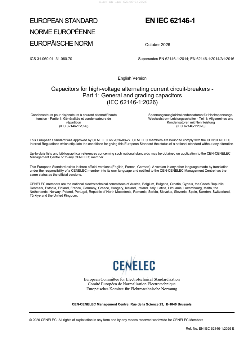
EUROPEAN STANDARD EN IEC 62146-1
NORME EUROPÉENNE
EUROPÄISCHE NORM October 2026
ICS 31.060.01; 31.060.70 Supersedes EN 62146-1:2014; EN 62146-1:2014/A1:2016
English Version
Capacitors for high-voltage alternating current circuit-breakers -
Part 1: General and grading capacitors
(IEC 62146-1:2026)
Condensateurs pour disjoncteurs à courant alternatif haute Spannungsausgleichskondensatoren für Hochspannungs-
tension - Partie 1: Généralités et condensateurs de Wechselstrom-Leistungsschalter - Teil 1: Allgemeines und
répartition Kondensatoren mit Nennleistung
(IEC 62146-1:2026) (IEC 62146-1:2026)
This European Standard was approved by CENELEC on 2026-08-27. CENELEC members are bound to comply with the CEN/CENELEC
Internal Regulations which stipulate the conditions for giving this European Standard the status of a national standard without any alteration.
Up-to-date lists and bibliographical references concerning such national standards may be obtained on application to the CEN-CENELEC
Management Centre or to any CENELEC member.
This European Standard exists in three official versions (English, French, German). A version in any other language made by translation
under the responsibility of a CENELEC member into its own language and notified to the CEN-CENELEC Management Centre has the
same status as the official versions.
CENELEC members are the national electrotechnical committees of Austria, Belgium, Bulgaria, Croatia, Cyprus, the Czech Republic,
Denmark, Estonia, Finland, France, Germany, Greece, Hungary, Iceland, Ireland, Italy, Latvia, Lithuania, Luxembourg, Malta, the
Netherlands, Norway, Poland, Portugal, Republic of North Macedonia, Romania, Serbia, Slovakia, Slovenia, Spain, Sweden, Switzerland,
Türkiye and the United Kingdom.
European Committee for Electrotechnical Standardization
Comité Européen de Normalisation Electrotechnique
Europäisches Komitee für Elektrotechnische Normung
CEN-CENELEC Management Centre: Rue de la Science 23, B-1040 Brussels
© 2026 CENELEC All rights of exploitation in any form and by any means reserved worldwide for CENELEC Members.
Ref. No. EN IEC 62146-1:2026 E
European foreword
The text of document 33/746/FDIS, future edition 2 of IEC 62146-1, prepared by TC 33 "Power
capacitors and their applications" was submitted to the IEC-CENELEC parallel vote and approved by
CENELEC as EN IEC 62146-1:2026.
The following dates are fixed:
• latest date by which the document has to be implemented at national (dop) 2027-10-31
level by publication of an identical national standard or by endorsement
• latest date by which the national standards conflicting with the (dow) 2029-10-31
document have to be withdrawn
This document supersedes EN 62146-1:2014 and all of its amendments and corrigenda (if any).
Attention is drawn to the possibility that some of the elements of this document may be the subject of
patent rights. CENELEC shall not be held responsible for identifying any or all such patent rights.
Any feedback and questions on this document should be directed to the users’ national committee. A
complete listing of these bodies can be found on the CENELEC website.
Endorsement notice
The text of the International Standard IEC 62146-1:2026 was approved by CENELEC as a European
Standard without any modification.
In the official version, for Bibliography, the following notes have to be added for the standard indicated:
IEC 60068-2-11 NOTE Approved as EN IEC 60068-2-11
IEC 60068-2-42 NOTE Approved as EN 60068-2-42
IEC 60721-3-2 NOTE Approved as EN IEC 60721-3-2
Annex ZA
(normative)
Normative references to international publications
with their corresponding European publications
The following documents are referred to in the text in such a way that some or all of their content
constitutes requirements of this document. For dated references, only the edition cited applies. For
undated references, the latest edition of the referenced document (including any amendments)
applies.
NOTE 1 Where an International Publication has been modified by common modifications, indicated by (mod),
the relevant EN/HD applies.
NOTE 2 Up-to-date information on the latest versions of the European Standards listed in this annex is available
here: www.cencenelec.eu.
Publication Year Title EN/HD Year
IEC 60060-1 - High-voltage test techniques - Part 1: EN IEC 60060-1 -
General terminology and test requirements
IEC 60068-2-17 2023 Environmental testing - Part 2-17: Tests - EN IEC 60068-2-17 2023
Test Q: Sealing
IEC 60071-2 2023 Insulation co-ordination - Part 2: EN IEC 60071-2 2023
Application guidelines
IEC 60270 2025 High-voltage test techniques - Charge- EN IEC 60270 2025
based measurement of partial discharges
IEC 60296 - Fluids for electrotechnical applications - EN IEC 60296 -
Mineral insulating oils for electrical
equipment
IEC 60567 - Oil-filled electrical equipment - Sampling of EN IEC 60567 -
free gases and analysis of free and
dissolved gases in mineral oils and other
insulating liquids - Guidance
IEC 60815 series Selection and dimensioning of high-voltage - -
insulators intended for use in polluted
conditions
IEC 60867 - Insulating liquids - Specifications for EN IEC 60867 -
unused liquids based on synthetic aromatic
hydrocarbons
IEC 61099 - Insulating liquids - Specifications for EN 61099 -
unused synthetic organic esters for
electrical purposes
IEC 61462 - Composite hollow insulators - Pressurized EN IEC 61462 -
and unpressurized insulators for use in
electrical equipment with AC rated voltage
greater than 1 000 V AC and D.C. voltage
greater than 1500V - Definitions, test
methods, acceptance criteria and design
recommendations
IEC 62146-2 2023 Capacitors for high-voltage alternating EN IEC 62146-2 2023
current circuit-breakers - Part 2: TRV
capacitors
IEC 62155 2003 Hollow pressurized and unpressurized EN 62155 2003
ceramic and glass insulators for use in
electrical equipment with rated voltages
greater than 1 000 V
IEC 62271-1 - High-voltage switchgear and controlgear - EN 62271-1 -
Part 1: Common specifications for
alternating current switchgear and
controlgear
IEC 62271-100 - High-voltage switchgear and controlgear - EN IEC 62271-100 -
Part 100: Alternating-current circuit-
breakers
IEC 62271-203 - High-voltage switchgear and controlgear - EN IEC 62271-203 -
Part 203: AC gas-insulated metal-enclosed
switchgear for rated voltages above 52 kV
IEC 62271-205 - High-voltage switchgear and controlgear - EN 62271-205 -
Part 205: Compact switchgear assemblies
for rated voltages above 52 kV
IEC 62271-300 - High-voltage switchgear and controlgear - - -
Part 300: Seismic qualification of
alternating current circuit-breakers
IEC 62770 - Fluids for electrotechnical applications - EN IEC 62770 -
Unused natural esters for transformers and
similar electrical equipment
IEC 63012 - Insulating liquids - Unused modified or EN IEC 63012 -
blended esters for electrotechnical
applications
IEC 62146-1 ®
Edition 2.0 2026-07
INTERNATIONAL
STANDARD
Capacitors for high-voltage alternating current circuit-breakers -
Part 1: General and grading capacitors
ICS 31.060.01; 31.060.70 ISBN 978-2-8327-1381-5
IEC 62146-1:2026-07(en)
IEC 62146-1:2026 © IEC 2026
CONTENTS
FOREWORD . 4
1 Scope . 6
2 Normative references . 6
3 Terms and definitions . 7
4 Abbreviated terms . 12
5 Service conditions . 13
5.1 General . 13
5.2 Normal service conditions . 13
5.2.1 Ambient temperature . 13
5.2.2 Altitude . 13
5.2.3 Mechanical stress and vibrations . 13
5.2.4 Additional service conditions for indoor and completely immersed
capacitor . 14
5.3 Special service conditions . 14
5.3.1 General . 14
5.3.2 Altitude correction. 14
5.3.3 Earthquakes . 15
6 Ratings . 15
6.1 Rated voltage (U ) . 15
cr
6.2 Rated insulation level . 16
6.3 Rated frequency (f ) . 17
r
7 Design and construction . 17
7.1 Capacitance tolerances . 17
7.2 Capacitor loss requirements. 17
7.3 Partial discharge level . 17
7.4 Angle of mounting . 17
7.5 Minimum withstand value of mechanical bending load . 18
7.5.1 Capacitors mounted on air insulated circuit-breaker . 18
7.5.2 Immersed capacitors . 18
7.6 Insulation fluids . 18
7.6.1 General . 18
7.6.2 Liquid insulation . 18
7.6.3 Gas insulation . 19
7.7 Protection against corrosion . 19
7.8 Marking of the equipment . 20
7.9 Creepage distances for outdoor capacitors . 20
8 Type tests . 20
8.1 Information for identification of specimens . 20
8.2 Information to be included in type-test reports. 21
8.3 Test conditions . 21
8.4 Dielectric type tests . 22
8.4.1 General . 22
8.4.2 Switching impulse voltage test . 22
8.4.3 Lightning and chopped lightning impulse voltage tests . 23
8.5 Voltage test at low and high temperature . 24
8.5.1 Test procedure . 24
IEC 62146-1:2026 © IEC 2026
8.5.2 Capacitor reduced-scale model design . 24
8.6 Radio interference voltage (RIV) test . 25
8.7 Power frequency withstand voltage test . 25
8.8 Short-circuit discharge test . 25
8.9 Resonance frequency measurements . 25
8.10 Mechanical bending test . 25
8.11 Tightness test at different temperatures . 26
8.12 Tightness test to check gas ingress from a pressurised environment . 26
8.13 Vibration test . 27
9 Routine tests . 27
9.1 General . 27
9.2 Test conditions . 28
9.3 Capacitance and tan δ (loss angle) measurement at power frequency . 28
9.4 Power frequency withstand voltage test . 29
9.5 Partial discharge test . 29
9.6 Tightness test . 30
9.6.1 General . 30
9.6.2 Oil impregnated capacitor . 30
9.6.3 Tightness test for gas filled capacitors . 31
9.7 Visual inspection and dimensional check . 31
10 Design test . 31
10.1 Aging test . 31
10.1.1 Test procedure . 31
10.1.2 Acceptance criteria . 32
11 Recommendations for transport, storage, installation, operation and maintenance . 32
11.1 General . 32
11.2 Conditions during transport, storage and installation . 33
11.3 Installation . 33
11.3.1 General . 33
11.3.2 Unpacking and lifting . 33
11.3.3 Assembly . 33
11.4 Operation . 34
11.5 Maintenance . 34
11.5.1 General . 34
11.5.2 Recommendation for the installation and maintenance . 34
12 Safety . 34
12.1 General . 34
12.2 Precautions by manufacturers . 34
12.3 Precautions by users . 35
12.4 National regulations . 35
13 Environmental aspects . 35
Annex A (informative) Corrosion: Information regarding service conditions and
recommended test requirements . 36
A.1 General . 36
A.2 Recommended test requirements . 36
Annex B (informative) Resonance frequency measurements . 37
B.1 General . 37
B.2 Time domain method . 37
IEC 62146-1:2026 © IEC 2026
B.2.1 General . 37
B.2.2 Test procedure . 37
B.2.3 Measurement results . 38
B.3 Frequency domain method . 39
B.3.1 General . 39
B.3.2 Test setup . 39
B.3.3 Measurement results . 39
Bibliography . 41
Figure 1 – Factor m for the switching impulse withstand test . 15
Figure 2 – Example of a dielectric type test sequence . 22
Figure 3 – Reduced scale model capacitor element geometry . 24
Figure 4 – Example of an electrical routine test sequence . 28
Figure B.1 – Example of test setup for resonance frequency measurements in time
domain (see 8.9) . 37
Figure B.2 – Example of time domain voltage transient response to calculate
resonance frequency (see 8.9) . 38
Figure B.3 – Wiring diagram of the measuring circuit for the high-frequency response
(adapted from IEC 60358-2, Annex AA) . 39
Figure B.4 – Frequency response of a high voltage capacitor: Impedance magnitude
(blue, solid line) and phase (red, dashed line) . 40
Table 1 – Partial discharge test voltages and permissible levels for grading capacitors . 17
IEC 62146-1:2026 © IEC 2026
INTERNATIONAL ELECTROTECHNICAL COMMISSION
____________
Capacitors for high-voltage alternating current circuit-breakers -
Part 1: General and grading capacitors
FOREWORD
1) The International Electrotechnical Commission (IEC) is a worldwide organization for standardization comprising
all national electrotechnical committees (IEC National Committees). The object of IEC is to promote international
co-operation on all questions concerning standardization in the electrical and electronic fields. To this end and
in addition to other activities, IEC publishes International Standards, Technical Specifications, Technical Reports,
Publicly Available Specifications (PAS) and Guides (hereafter referred to as "IEC Publication(s)"). Their
preparation is entrusted to technical committees; any IEC National Committee interested in the subject dealt with
may participate in this preparatory work. International, governmental and non-governmental organizations liaising
with the IEC also participate in this preparation. IEC collaborates closely with the International Organization for
Standardization (ISO) in accordance with conditions determined by agreement between the two organizations.
2) The formal decisions or agreements of IEC on technical matters express, as nearly as possible, an international
consensus of opinion on the relevant subjects since each technical committee has representation from all
interested IEC National Committees.
3) IEC Publications have the form of recommendations for international use and are accepted by IEC National
Committees in that sense. While all reasonable efforts are made to ensure that the technical content of IEC
Publications is accurate, IEC cannot be held responsible for the way in which they are used or for any
misinterpretation by any end user.
4) In order to promote international uniformity, IEC National Committees undertake to apply IEC Publications
transparently to the maximum extent possible in their national and regional publications. Any divergence between
any IEC Publication and the corresponding national or regional publication shall be clearly indicated in the latter.
5) IEC itself does not provide any attestation of conformity. Independent certification bodies provide conformity
assessment services and, in some areas, access to IEC marks of conformity. IEC is not responsible for any
services carried out by independent certification bodies.
6) All users should ensure that they have the latest edition of this publication.
7) No liability shall attach to IEC or its directors, employees, servants or agents including individual experts and
members of its technical committees and IEC National Committees for any personal injury, property damage or
other damage of any nature whatsoever, whether direct or indirect, or for costs (including legal fees) and
expenses arising out of the publication, use of, or reliance upon, this IEC Publication or any other IEC
Publications.
8) Attention is drawn to the Normative references cited in this publication. Use of the referenced publications is
indispensable for the correct application of this publication.
9) IEC draws attention to the possibility that the implementation of this document may involve the use of (a)
patent(s). IEC takes no position concerning the evidence, validity or applicability of any claimed patent rights in
respect thereof. As of the date of publication of this document, IEC had not received notice of (a) patent(s), which
may be required to implement this document. However, implementers are cautioned that this may not represent
the latest information, which may be obtained from the patent database available at https://patents.iec.ch. IEC
shall not be held responsible for identifying any or all such patent rights.
IEC 62146-1 has been prepared by IEC technical committee 33: Power capacitors and their
applications. It is an International Standard.
This second edition cancels and replaces the first edition published in 2016. This edition
constitutes a technical revision.
This edition includes the following significant technical changes with respect to the previous
edition:
a) Clause re-ordering and reworked sentences;
b) New type and special tests.
IEC 62146-1:2026 © IEC 2026
The text of this International Standard is based on the following documents:
Draft Report on voting
33/746/FDIS 33/750/RVD
Full information on the voting for its approval can be found in the report on voting indicated in
the above table.
The language used for the development of this International Standard is English.
This document was drafted in accordance with ISO/IEC Directives, Part 2, and developed in
accordance with ISO/IEC Directives, Part 1 and ISO/IEC Directives, IEC Supplement, available
at www.iec.ch/members_experts/refdocs. The main document types developed by IEC are
described in greater detail at www.iec.ch/publications.
A list of all parts in the IEC 62146 series, published under the general title Capacitors for
high-voltage alternating current circuit-breakers, can be found on the IEC website.
Future documents in this series will carry the new general title as cited above. Titles of existing
documents in this series will be updated at the time of the next edition.
The committee has decided that the contents of this document will remain unchanged until the
stability date indicated on the IEC website under webstore.iec.ch in the data related to the
specific document. At this date, the document will be
– reconfirmed,
– withdrawn, or
– revised.
IEC 62146-1:2026 © IEC 2026
1 Scope
This part of IEC 62146 includes generalities of capacitors used on alternating current circuit-
breakers and introduces specifications for grading capacitors. Regarding grading capacitors,
their function is to control the voltage distribution across the individual interrupter units of a
multi-break circuit-breaker.
Capacitors can also be used in parallel to the interrupter unit on single break circuit-breakers
to modify the Transient Recovery Voltage (TRV). This TRV capacitor application is covered by
IEC 62146-2:2023.
Capacitors for high-voltage alternating circuit breakers are sub-components for the circuit-
breaker and are specified in accordance with the circuit-breaker specifications according to
IEC 62271-1, IEC 62271-100, and if applicable to IEC 62271-203.
This document applies to grading capacitors falling into one or both of the following categories
for:
− mounting on air-insulated circuit-breakers.
− mounting on enclosed circuit-breakers (for example immersed in insulating gas, in oil, etc.).
The testing for each of the above applications is in some cases different.
The object of this document is:
− to define uniform rules regarding performances, testing and rating;
− to define specific safety rules;
− to provide a guidance for installation and operation.
NOTE CIGRÉ TB-368 presents a study about the operating environment of voltage grading capacitors applied to
high-voltage circuit-breakers (see [2] ).
This document does not apply to capacitors not directly associated with high-voltage alternating
current circuit-breakers.
2 Normative references
The following documents are referred to in the text in such a way that some or all of their content
constitutes requirements of this document. For dated references, only the edition cited applies.
For undated references, the latest edition of the referenced document (including any
amendments) applies.
IEC 60060-1, High-voltage test techniques - Part 1: General terminology and test requirements
IEC 60068-2-17:2023, Environmental testing - Part 2-17: Tests - Test Q: Sealing
IEC 60071-2:2023, Insulation co-ordination - Part 2: Application guidelines
IEC 60270:2025, High-voltage test techniques - Charge-based measurement of partial
discharges
IEC 60296, Fluids for electrotechnical applications - Mineral insulating oils for electrical
equipment
___________
Numbers in square brackets refer to the Bibliography.
IEC 62146-1:2026 © IEC 2026
IEC 60567, Oil-filled electrical equipment - Sampling of gases and analysis of free and
dissolved gases in mineral oils and other insulating liquids - Guidance
IEC 60815 (all parts), Selection and dimensioning of high-voltage insulators intended for use in
polluted conditions
IEC 60867, Insulating liquids - Specifications for unused liquids based on synthetic aromatic
hydrocarbons
IEC 61099, Insulating liquids - Specifications for unused synthetic organic esters for electrical
purposes
IEC 61462, Composite hollow insulators - Pressurized and unpressurized insulators for use in
electrical equipment with AC rated voltage greater than 1 000 V AC and DC voltage greater
than 1 500 V - Definitions, test methods, acceptance criteria and design recommendations
IEC 62146-2:2023, Capacitors for high‑voltage alternating current circuit‑breakers - Part 2: TRV
capacitors
IEC 62155:2003, Hollow pressurized and unpressurized ceramic and glass insulators for use in
electrical equipment with rated voltages greater than 1 000 V
IEC 62271-1, High-voltage switchgear and controlgear - Part 1: Common specifications for
alternating current switchgear and controlgear
IEC 62271-100, High-voltage switchgear and controlgear - Part 100: Alternating-current circuit-
breakers
IEC 62271-203, High-voltage switchgear and controlgear - Part 203: AC gas-insulated metal-
enclosed switchgear for rated voltages above 52 kV
IEC 62271-205, High-voltage switchgear and controlgear - Part 205: Compact switchgear
assemblies for rated voltages above 52 kV
IEC 62271-300, High-voltage switchgear and controlgear - Part 300: Seismic qualification of
alternating current circuit-breakers
IEC 62770, Fluids for electrotechnical applications - Unused natural esters for transformers and
similar electrical equipment
IEC 63012, Insulating liquids - Unused modified or blended esters for electrotechnical
applications
3 Terms and definitions
For the purposes of this document, the following terms and definitions apply.
ISO and IEC maintain terminology databases for use in standardization at the following
addresses:
– IEC Electropedia: available at https://www.electropedia.org/
– ISO Online browsing platform: available at https://www.iso.org/obp
IEC 62146-1:2026 © IEC 2026
3.1
arcing distance
shortest distance in the air external to the insulator between the metallic parts which normally
have the operating voltage between them
[SOURCE: IEC 60050-471:2007, 471-01-01]
3.2
capacitor element
device consisting essentially of two electrodes separated by a dielectric
[SOURCE: IEC 60050-436:1990, 436-01-03]
3.3
capacitor losses
active power dissipated in the capacitor
[SOURCE: IEC 60050-436:1990, 436-04-10]
3.4
capacitor terminals
terminals intended for electrical and mechanical connection to the terminals of the interrupter
units of circuit-breakers
3.5
capacitance tolerance
permissible difference between the actual capacitance and the rated capacitance under
specified conditions
Note 1 to entry: The actual capacitance should be measured at, or referred to, the temperature at which the rated
capacitance is defined.
[SOURCE: IEC 60050-436:1990, 436-04-01, modified by addition of Note to entry.]
3.6
capacitor unit
assembly of one or more capacitor elements connected together and in the same container with
terminals brought out
Note 1 to entry: A common type of unit for grading capacitors has a cylindrical housing of insulating material and
metal end flanges which serve as terminals.
[SOURCE: IEC 60050-436:1990, 436-01-04, modified by addition of Note to entry]
3.7
completely immersed capacitor
capacitor, both ends of which are intended to be immersed in insulating media other than
ambient air (e.g. oil or gas)
[SOURCE: IEC 60050-471:2007, 471-02-04, modified - definition originally referred to "bushing"
instead of "capacitor".]
IEC 62146-1:2026 © IEC 2026
3.8
creepage distance
shortest distance along the surface of a solid insulating material between two conductive parts
Note 1 to entry: The surface of cement or any other non-insulating jointing material is not considered as forming
part of the creepage distance.
Note 2 to entry: If high-resistance coating is applied to parts of the insulating part of an insulator, such parts are
considered to be effective insulating surface and the distance over them is included in the creepage distance.
[SOURCE: IEC 60050-604:1987, 604-03-61, modified by addition of Notes to entry.]
3.9
dielectric (of a capacitor)
insulating material between the electrodes of the capacitor element
Note 1 to entry: The major insulation generally consists of paper, plastic film, or a mixed of paper and plastic film
subsequently treated and impregnated with oil or gas at atmospheric pressure or higher.
3.10
external insulation
distance through the air and the surfaces in contact with the air of the grading capacitor that
are subjected to dielectric stresses
Note 1 to entry: They are also subject to the effects of the atmospheric and other external conditions such as
pollution, humidity, ice, vermin, etc.
3.11
failure
termination of the ability of an item to perform a required function
Note 1 to entry: After failure the item has a fault.
Note 2 to entry: "Failure" is an event, as distinguished from "fault", which is a state.
Note 3 to entry: This concept as defined does not apply to items consisting of software only.
[SOURCE: IEC 60050-191:1990, 191-04-01]
3.12
flashover
electric breakdown between conductors in a gas or in a liquid or in a vacuum, at least partly
along the surface of solid insulation
[SOURCE: IEC 60050-212:2012, 212-11-47]
3.13
grading capacitor
capacitor for installation on high-voltage circuit-breakers to control the voltage distribution
across the individual interrupter unit
Note 1 to entry: The grading capacitors alone are accessories of the circuit-breaker.
3.14
indoor capacitor
capacitor, both ends of which are intended to be in ambient air at atmospheric pressure but not
exposed to outdoor atmospheric conditions
[SOURCE: IEC 60050-471:2007, 471-02-05, modified - definition originally referred to "bushing"
instead of "capacitor".]
IEC 62146-1:2026 © IEC 2026
3.15
insulating envelope
insulator which is open from end to end, with or without sheds, including end fittings
Note 1 to entry: An insulating envelope can be made from one or more permanently assembled insulating elements.
Note 2 to entry: The insulating envelope may be in ceramic, glass or analogous inorganic material, cast or moulded
resin, composite insulating material, in one piece or more pieces permanently assembled.
[SOURCE: IEC 60050-471:2007, 471-01-08, modified - definition originally referred to a hollow
insulator and Note 2 to entry has been added.]
3.16
outdoor capacitor
capacitor, both ends of which are intended to be in ambient air at atmospheric pressure, and
exposed to outdoor atmospheric conditions
[SOURCE: IEC 60050-471:2007, 471-02-07, modified - definition originally referred to "bushing"
instead of "capacitor".]
3.17
internal insulation
internal solid, liquid or gaseous parts of the insulation of the grading capacitor which are
protected from the effects of atmospheric conditions
Note 1 to entry: The parts are also protected from other external conditions such as pollution, humidity, ice, vermin,
etc.
3.18
mechanical stress
any mechanical stress applied to the insulating envelope and to the terminals of the capacitor
Note 1 to entry: It is a function of the following main forces:
− forces on the terminals due to the circuit-breaker connection;
− forces due to the wind and ice;
− seismic forces;
− forces due to the operating conditions, opening and closing, of the circuit- breaker;
− thermal forces due to the ambient medium conditions;
− forces due to the transportation of the circuit-breaker or capacitors.
3.19
puncture
disruptive discharge occurring through a solid insulation material, producing a path of
permanent damage
Note 1 to entry: The term puncture is also used as a synonym for electrical breakdown in solids.
[SOURCE: IEC 60050-212:2010, 212-11-49]
3.20
rated capacitance of a capacitor
C
r
capacitance value for which the capacitor has been designed
IEC 62146-1:2026 © IEC 2026
3.21
rated chopped lightning impulse withstand voltage
required peak value of the chopped lightning impulse withstand voltage which characterises the
insulation of a capacitor as regards the withstand tests
Note 1 to entry: The definitions and the standard parameters applicable to chopped impulses are specified in
IEC 60060-1.
3.22
rated frequency of a capacitor
f
r
frequency for which the capacitor has been designed
[SOURCE: IEC 60050-436:1990, 436-01-14, modified by addition of symbol.]
3.23
rated insulation level
test voltages, under specified conditions, that the insulation is designed to withstand
Note 1 to entry: These test voltages can be for instance:
a) rated chopped and lightning impulse and short duration power frequency withstand voltages for capacitors
installed on circuit-breaker with rated voltage lower than 300 kV.
b) rated switching, lightning, chopped impulse and short duration power frequency withstand voltages for capacitors
installed on circuit-breaker with rated voltage equal to or greater than 300 kV.
Note 2 to entry: The rated insulation levels of the capacitor should be equal to or higher than the relevant
requirements for the circuit-breaker interrupting unit.
[SOURCE: IEC 60050-421:1990, 421-09-02, modified Note to entry]
3.24
rated lightning impulse withstand voltage
U
C LI
required peak value of the lightning impulse withstand voltage which characterises the
insulation of an equipment as regards the withstand tests
Note 1 to entry: The standard lightning impulse has a front time of 1,2 µs and a time-to-half-value of 50 µs as
specified in IEC 60060-1.
3.25
rated short duration power frequency withstand voltage
U
C PF
required RMS value of sinusoidal power frequency voltage that the equipment withstands during
tests made under specified conditions and for a duration of 1 min unless otherwise specified
3.26
rated switching impulse withstand voltage
U
C SI
required peak value of the switching impulse withstand voltage which characterises the
insulation of an equipment as regards the withstand tests
Note 1 to entry: The standard switching impulse has a time-to-crest of 250 µs and a time-to-half-value of 2 500 µs
as specified in IEC 60060-1.
3.27
rated temperature category (of a capacitor)
range of temperature of the ambient air or other medium in which the capacitor is immersed
during the service life and for which it has been designed
IEC 62146-1:2026 © IEC 2026
3.28
rated voltage of a capacitor
U
cr
RMS value of the alternating voltage assigned to the capacitor for identification and at which
the capacitor is designed to operate continuously
3.29
rated voltage of circuit-breaker
U
r
indicates the upper limit of the highest voltage of systems for which the circuit-breaker is
intended
Note 1 to entry: See IEC 62271-1.
Note 2 to entry: U used in IEC 62271-1 series corresponds to Um presented in IEC 60071.
r
3.30
resonance frequency
frequency for which the reactance of the intrinsic capacitance of the capacitor is equal to the
reactance of the self-inductance of the capacitor
3.31
sample
device for testing
Note 1 to entry: Examples of such devices are a complete small capacitor, or the housing of a grading capacitor
with metal end flanges filled with impregnating fluid.
3.32
tangent of the loss angle of a capacitor
tan δ
ratio between the equivalent series resistance and the capacitive reactance of a capacitor at
specified sinusoidal alternating voltage and frequency
[SOURCE: IEC 60050-436:1990, 436-04-11]
3.33
voltage grading factor of a circuit-breaker
F
VG
value that defines the standard values of rated voltages for the grading capacitor
Note 1 to entry: This factor is the ratio between the actual maximum power frequency voltage fraction across one
interrupter unit of a multi-break circuit-breaker and the calculated linear power frequency voltage distribution per
interrupting unit.
Note 2 to entry: It is dependent on the circuit-breaker design, of the capacitance value of the grading capacitor and
its tolerance and of the safety margin.
4 Abbreviated terms
TRV Transient Recovery Voltage
Rated capacitance of a capacitor
C
r
f Rated frequency of a capacitor
r
U Rated voltage of a capacitor
cr
U Rated voltage of circuit-breaker
r
tan δ Tangent of the loss angle of a capacitor
F Voltage grading factor of a circuit-breaker
VG
IEC 62146-1:2026 © IEC 2026
U Rated short-duration power frequency withstand voltage for the grading capacitor
C PF
U Rated short-duration power frequency withstand voltage across the open circuit-
PF
breaker
U Rated lightning impulse withstand voltage for the grading capacitor
C LI
U Combined lightning and power frequency withstand voltage for the circuit-breaker
(L
...