


EN IEC 62052-11:2021/prAC:2026
(Amendment)Electricity metering equipment - General requirements, tests and test conditions - Part 11: Metering equipment
General Information
- Abstract
This part of IEC 62052 specifies requirements and associated tests, with their appropriate conditions for type testing of AC and DC electricity meters. This document details functional, mechanical, electrical and marking requirements, test methods, and test conditions, including immunity to external influences covering electromagnetic and climatic environments.
- Status
- Not Published
- Publication Date
- 11-Nov-2026
- Technical Committee
- CLC/TC 13 - Equipment for electrical energy measurement and load control
- Current Stage
- 4020 - Enquiry circulated - Enquiry
- Start Date
- 24-Jul-2026
- Due Date
- 25-Jun-2025
- Completion Date
- 24-Jul-2026

Overview
EN IEC 62052-11:2021/prAC:2026 is a European draft amendment standard developed by CLC/TC 13, focusing on electricity metering equipment. This part of the IEC 62052 series sets out the general requirements, tests, and test conditions for both AC and DC electricity meters. The standard outlines functional, mechanical, electrical, and marking requirements, as well as comprehensive test methods and conditions for type testing. Additionally, it stipulates immunity requirements for external influences, encompassing electromagnetic and climatic environments. The purpose is to ensure that electricity meters installed in today's varied environments are reliable, accurate, safe, and compliant with EU directives such as MID (Measuring Instruments Directive) and EMCD (Electromagnetic Compatibility Directive).
Key Topics
- Scope and Definitions: Addresses functional, mechanical, electrical, and safety features necessary for modern electricity meters. Provides updated definitions to align with current industry practices and international terminology.
- Type Testing Procedures: Details the conditions and methods for verifying compliance, including tests for metrological performance, mechanical robustness, marking, climatic impacts, and immunity to electromagnetic disturbances.
- Test Conditions and Requirements: Specifies the laboratory conditions, test sequences, and cable connections required to assess meter performance under typical and extreme use scenarios.
- Electrical and Climatic Immunity: Establishes requirements for immunity to external influences such as electromagnetic fields, voltage surges, and environmental stresses (humidity, temperature, altitude).
- Documentation and Marking: Defines what information must be present on the meter, packaging, and documentation, including user, installation, and maintenance manuals to ensure correct installation, operation, and servicing.
- Safety and Compliance Updates: Updates references to the latest versions of safety and EMC standards and adapts requirements to recent advances in technology and regulation.
Applications
EN IEC 62052-11:2021/prAC:2026 is applicable to:
- Electricity Meters for Billing: Ensures accurate measurement and registration of electric energy for customer billing in residential, commercial, and industrial sectors.
- Smart Metering Infrastructure: Supports integration with smart grids, enabling two-way communication, remote reading, and intelligent load management.
- AC and DC Metering: Provides requirements for a wide range of meters, including those for alternating current (AC) and direct current (DC), covering both direct connect and transformer-operated types.
- Utility-Scale Installations: Used by utilities and network operators for compliance with European regulations and cross-border harmonization of metering practices.
- Quality Assurance in Manufacturing: Provides benchmarks for manufacturers to assess product compliance during development and prior to market release.
Related Standards
The following standards are referenced or closely related to the requirements within EN IEC 62052-11:2021/prAC:2026:
- EN IEC 62052-31:2024: Product safety requirements and tests for electricity metering equipment.
- IEC 62057-1:2023: Test equipment and procedures for stationary meter test units.
- EN 50470-3:2022 / EN 50470-4:2023: Specific requirements for electronic electricity meters.
- IEC 61000-4 series: Electromagnetic compatibility test methods, including radiated immunity, surge, and conducted disturbances.
- IEC 62053 & IEC 62058 series: Particular requirements for active and reactive energy meters and transformer-operated meters.
- IEC 60404-8-4:2022: Magnetic materials specifications for applicable meter construction.
By adhering to EN IEC 62052-11:2021/prAC:2026, manufacturers, utilities, and testing organizations ensure that electricity metering equipment is standardized for accuracy, reliability, safety, and electromagnetic compatibility, meeting both current and evolving energy market needs.
Keywords: electricity metering, AC meter, DC meter, type testing, electromagnetic compatibility, climatic requirements, metrological performance, CENELEC, EN IEC 62052, smart meter standard, electricity meter compliance.
Relations
- Effective Date
- 30-Apr-2024
- Effective Date
- 18-Mar-2025
Get Certified
Connect with accredited certification bodies for this standard

BSMI (Bureau of Standards, Metrology and Inspection)
Taiwan's standards and inspection authority.
Sponsored listings
Frequently Asked Questions
EN IEC 62052-11:2021/prAC:2026 is a draft published by CLC. Its full title is "Electricity metering equipment - General requirements, tests and test conditions - Part 11: Metering equipment". This standard covers: This part of IEC 62052 specifies requirements and associated tests, with their appropriate conditions for type testing of AC and DC electricity meters. This document details functional, mechanical, electrical and marking requirements, test methods, and test conditions, including immunity to external influences covering electromagnetic and climatic environments.
This part of IEC 62052 specifies requirements and associated tests, with their appropriate conditions for type testing of AC and DC electricity meters. This document details functional, mechanical, electrical and marking requirements, test methods, and test conditions, including immunity to external influences covering electromagnetic and climatic environments.
EN IEC 62052-11:2021/prAC:2026 is classified under the following ICS (International Classification for Standards) categories: 17.220.20 - Measurement of electrical and magnetic quantities. The ICS classification helps identify the subject area and facilitates finding related standards.
EN IEC 62052-11:2021/prAC:2026 has the following relationships with other standards: It is inter standard links to EN IEC 62052-11:2021, prEN IEC 62052-11:2026. Understanding these relationships helps ensure you are using the most current and applicable version of the standard.
EN IEC 62052-11:2021/prAC:2026 is associated with the following European legislation: EU Directives/Regulations: 2014/30/EU, 2014/32/EU; Standardization Mandates: M/541, M/552. When a standard is cited in the Official Journal of the European Union, products manufactured in conformity with it benefit from a presumption of conformity with the essential requirements of the corresponding EU directive or regulation.
EN IEC 62052-11:2021/prAC:2026 is available in PDF format for immediate download after purchase. The document can be added to your cart and obtained through the secure checkout process. Digital delivery ensures instant access to the complete standard document.
Standards Content (Sample)
SLOVENSKI STANDARD
01-september-2026
Oprema za merjenje električne energije - Splošne zahteve, preskusi in
preskuševalni pogoji - 11. del: Merilna oprema
Electricity metering equipment - General requirements, tests and test conditions - Part
11: Metering equipment
Elektrizitätszähler – Allgemeine Anforderungen, Prüfungen und Prüfbedingungen - Teil
11: Messeinrichtungen
Équipement de comptage de l'électricité – Exigences générales, essais et conditions
d'essai - Partie 11: Équipement de comptage
Ta slovenski standard je istoveten z: EN IEC 62052-11:2021/prAC:2026
ICS:
17.220.20 Merjenje električnih in Measurement of electrical
magnetnih veličin and magnetic quantities
91.140.50 Sistemi za oskrbo z elektriko Electricity supply systems
2003-01.Slovenski inštitut za standardizacijo. Razmnoževanje celote ali delov tega standarda ni dovoljeno.
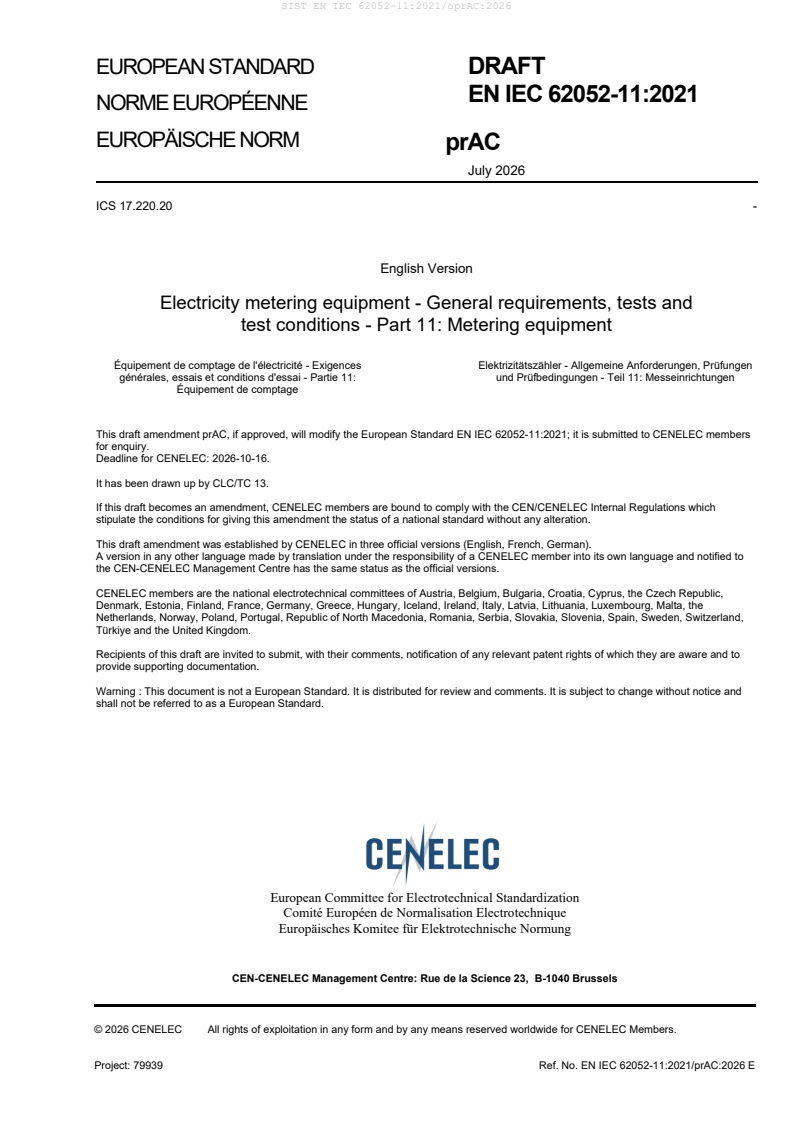
EUROPEAN STANDARD DRAFT
EN IEC 62052-11:2021
NORME EUROPÉENNE
EUROPÄISCHE NORM
prAC
July 2026
ICS 17.220.20 -
English Version
Electricity metering equipment - General requirements, tests and
test conditions - Part 11: Metering equipment
Équipement de comptage de l'électricité - Exigences Elektrizitätszähler - Allgemeine Anforderungen, Prüfungen
générales, essais et conditions d'essai - Partie 11: und Prüfbedingungen - Teil 11: Messeinrichtungen
Équipement de comptage
This draft amendment prAC, if approved, will modify the European Standard EN IEC 62052-11:2021; it is submitted to CENELEC members
for enquiry.
Deadline for CENELEC: 2026-10-16.
It has been drawn up by CLC/TC 13.
If this draft becomes an amendment, CENELEC members are bound to comply with the CEN/CENELEC Internal Regulations which
stipulate the conditions for giving this amendment the status of a national standard without any alteration.
This draft amendment was established by CENELEC in three official versions (English, French, German).
A version in any other language made by translation under the responsibility of a CENELEC member into its own language and notified to
the CEN-CENELEC Management Centre has the same status as the official versions.
CENELEC members are the national electrotechnical committees of Austria, Belgium, Bulgaria, Croatia, Cyprus, the Czech Republic,
Denmark, Estonia, Finland, France, Germany, Greece, Hungary, Iceland, Ireland, Italy, Latvia, Lithuania, Luxembourg, Malta, the
Netherlands, Norway, Poland, Portugal, Republic of North Macedonia, Romania, Serbia, Slovakia, Slovenia, Spain, Sweden, Switzerland,
Türkiye and the United Kingdom.
Recipients of this draft are invited to submit, with their comments, notification of any relevant patent rights of which they are aware and to
provide supporting documentation.
Warning : This document is not a European Standard. It is distributed for review and comments. It is subject to change without notice and
shall not be referred to as a European Standard.
European Committee for Electrotechnical Standardization
Comité Européen de Normalisation Electrotechnique
Europäisches Komitee für Elektrotechnische Normung
CEN-CENELEC Management Centre: Rue de la Science 23, B-1040 Brussels
© 2026 CENELEC All rights of exploitation in any form and by any means reserved worldwide for CENELEC Members.
Project: 79939 Ref. No. EN IEC 62052-11:2021/prAC:2026 E
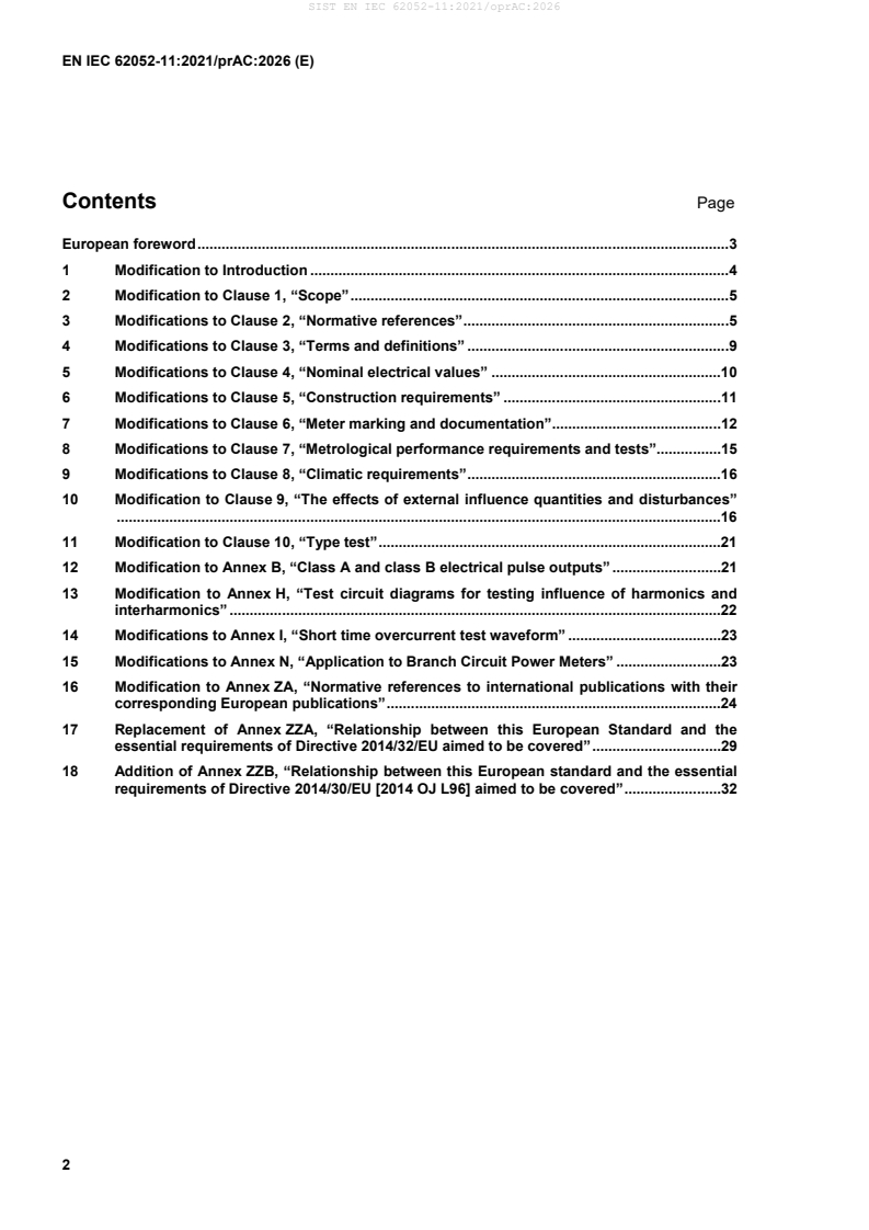
Contents Page
European foreword . 3
1 Modification to Introduction . 4
2 Modification to Clause 1, “Scope” . 5
3 Modifications to Clause 2, “Normative references” . 5
4 Modifications to Clause 3, “Terms and definitions” . 9
5 Modifications to Clause 4, “Nominal electrical values” .10
6 Modifications to Clause 5, “Construction requirements” .11
7 Modifications to Clause 6, “Meter marking and documentation”.12
8 Modifications to Clause 7, “Metrological performance requirements and tests”.15
9 Modifications to Clause 8, “Climatic requirements” .16
10 Modification to Clause 9, “The effects of external influence quantities and disturbances”
......................................................................................................................................................16
11 Modification to Clause 10, “Type test” .21
12 Modification to Annex B, “Class A and class B electrical pulse outputs” .21
13 Modification to Annex H, “Test circuit diagrams for testing influence of harmonics and
interharmonics” .22
14 Modifications to Annex I, “Short time overcurrent test waveform” .23
15 Modifications to Annex N, “Application to Branch Circuit Power Meters” .23
16 Modification to Annex ZA, “Normative references to international publications with their
corresponding European publications” .24
17 Replacement of Annex ZZA, “Relationship between this European Standard and the
essential requirements of Directive 2014/32/EU aimed to be covered” .29
18 Addition of Annex ZZB, “Relationship between this European standard and the essential
requirements of Directive 2014/30/EU [2014 OJ L96] aimed to be covered” .32
European foreword
This document (EN IEC 62052-11:2021/prAC:2026) has been prepared by CLC/TC 13 “Electrical energy
measurement and control”.
This document is currently submitted to the Enquiry.
The following dates are proposed:
• latest date by which the existence of this (doa) dav + 6 months
document has to be announced at national level
• latest date by which this document has to be (dop) dav + 12 months
implemented at national level by publication of
an identical national standard or by
endorsement
• latest date by which the national standards (dow) dav + 36 months
conflicting with this document have to be (to be confirmed or
withdrawn modified when voting)
This document modifies EN IEC 62052-11:2021.
EN IEC 62052-11:2021:
— modification of the reference for safety requirements from IEC 62052-31:2015 to IEC 62052-31:2024
— adaptation of Clause 9 and Annex H with an additional test waveform to ensure immunity against severe
current transients.
— adaptation of the whole document to MID and EMCD, addition of Annexes ZZA and ZZB.
This document is read in conjunction with EN IEC 62052-11:2021, EN IEC 62052-11:2021/A11:2022 and
EN IEC 62052-11:2021/A12:2024.
This document has been prepared under Standardization Requests given to CENELEC by the European
Commission. The Standing Committee of the EFTA States subsequently approves these requests for its
Member States.
For the relationship with EU Legislation, see informative Annexes ZZA and ZZB, which are an integral part of
this document.
1 Modification to Introduction
In the Introduction, replace the second table with the following:
“
PRODUCT FAMILY STANDARDS –
PARTICULAR REQUIREMENTS AND ACCURACY CLASSES
AC meters for DC meters for
AC meters rated up to 1
connection connection
000 V for direct
DC meters rated up through LPITs (as through LPITs (as
connection or connection Tariff and load
to 1 500 V for direct defined in the defined in the
through control equipment
connection IEC 61869 IEC 61869
conventional
series of series of
transformers
standards) standards)
Static, active energy
directly connected, and Static, active energy,
transformer operated, directly connected,
classes A, B, C classes A, B, C
EN 50470-3:2022 EN 50470-4:2023
/A1:20XX
Electromechanical, active
Planned: Planned:
energy directly Static, DC energy,
Ripple control
connected, directly connected,
LPIT operated LPIT operated
receivers
classes 0,5, 1, 2 classes 0,5, 1
meters meters
IEC 62054-11:2004
IEC 62053-11:2003, IEC 62053-41 –
IEC 62053-xx IEC 62053-xx
IEC 62058-21:2008
Static, active energy
directly connected, and
transformer operated,
Time switches
— — —
classes 1, 2
IEC 62054-21:2004
IEC 62053-21:2020,
IEC 62058-31:2008,
Static, active energy,
transformer operated,
classes 0,1S, 0,2S, 0,5S
— — — —
IEC 62053-22:2020,
IEC 62058-31:2008
Static, reactive energy
directly connected, and
transformer operated,
— — — —
classes 2, 3
IEC 62053-23:2020
Static, reactive energy
directly connected, and
transformer operated,
— — — —
classes 0,5 S, 1S, 1, 2, 3
IEC 62053-24:2020
Static, active energy directly
connected, prepayment
— — — —
classes 1, 2
IEC 62055-31:2005
NOTE The standards in the table above are referred to as “the relevant particular requirements (accuracy class)
standards” throughout the document.”
“
In the Introduction and throughout the text, replace
“
IEC 62057-1, Test equipment, techniques and procedures for electrical energy meters – Part 1: Stationary Meter
Test Units (MTU)
“
with
“
IEC 62057-1:2023, Electrical energy meters – Test equipment, techniques and procedures – Part 1: Stationary
meter test units (MTUs)
“
In the last paragraph, delete “For special application, other test levels may be used and are subject to an
agreement between the manufacturer and the purchaser.”
2 Modification to Clause 1, “Scope”
In the 2nd paragraph, delete the 4th list item starting with “Operate with detached …”
Add the following NOTE 10 after NOTE 9:
“
NOTE 10 Nominal values, accuracy classes, requirements and test methods for reference standard meters are specified
in IEC 62057-1:2023.”
Renumber the subsequent notes: NOTE 11 to NOTE 14.
Replace (newly numbered) NOTE 11 with the following:
“
NOTE 11 Nevertheless, specific tampering detection and prevention requirements, and test methods, as relevant for a
particular market can be defined.“
3 Modifications to Clause 2, “Normative references”
In Clause 2 and throughout the text, replace
“
IEC 60404-8-4:2013, Magnetic materials – Part 8-4: Specifications for individual materials – Cold-rolled non-
oriented electrical steel strip and sheet delivered in the fully-processed state
”
with
“
IEC 60404-8-4:2022, Magnetic materials – Part 8-4: Specifications for individual materials – Cold-rolled non-
oriented electrical steel strip and sheet delivered in the fully-processed state
”
Delete
“
IEC 60664-1:2007, Insulation coordination for equipment within low-voltage systems – Part 1: Principles,
requirements and tests
“
In Clause 2 and throughout the text, replace
“
IEC 60721-1:1990, Classification of environmental conditions – Part 1: Environmental parameters and their
severities
”
with
“
IEC 60721-1:1990, Classification of environmental conditions – Part 1: Environmental parameters and
their severities
”
Delete
“
IEC 60947-1:2007, Low-voltage switchgear and controlgear – Part 1: General rules
IEC 60947-1:2007/AMD1:2010
IEC 60947-1:2007/AMD2:2014
“
In Clause 2 and throughout the text, replace
“
IEC 61000-4-3:2006, Electromagnetic compatibility (EMC) – Part 4-3: Testing and measurement techniques –
Radiated, radio-frequency, electromagnetic field immunity test
”
with
“
IEC 61000-4-3:2020, Electromagnetic compatibility (EMC) – Part 4-3: Testing and measurement techniques –
Radiated, radio-frequency, electromagnetic field immunity test
”
In Clause 2 and throughout the text, replace
“
IEC 61000-4-11:2020, Electromagnetic compatibility (EMC) – Part 4-11: Testing and measurement techniques
– Voltage dips, short interruptions and voltage variations immunity tests for equipment with input current up to
16 A per phase
”
with
As impacted by IEC 60721-1:1990/AMD1:1992 and IEC 60721-1:1990/AMD1:1995.
“
IEC 61000-4-11:2020, Electromagnetic compatibility (EMC) – Part 4-11: Testing and measurement techniques
– Voltage dips, short interruptions and voltage variations immunity tests for equipment with input current up to
16 A per phase
”
In Clause 2 and throughout the text, replace
“
IEC 61000-4-18:2019, Electromagnetic compatibility (EMC) – Part 4-18: Testing and measurement techniques
– Damped oscillatory wave immunity test
”
with
“
IEC 61000-4-18:2019, Electromagnetic compatibility (EMC) – Part 4-18: Testing and measurement techniques
– Damped oscillatory wave immunity test
”
In Clause 2 and throughout the text, replace
“
IEC 61000-4-20:2010, Electromagnetic compatibility (EMC) – Part 4-20: Testing and measurement techniques
– Emission and immunity testing in transverse electromagnetic (TEM) waveguides
”
with
“
IEC 61000-4-20:2022, Electromagnetic compatibility (EMC) – Part 4-20: Testing and measurement techniques
– Emission and immunity testing in transverse electromagnetic (TEM) waveguides
”
In Clause 2 and throughout the text, replace
“
IEC 61000-4-5:2014/AMD1:2017, Electromagnetic compatibility (EMC) – Part 4: Testing and measurement
techniques – Section 5: Surge immunity test
”
with
“
IEC 61000-4-5:2014, Electromagnetic compatibility (EMC) – Part 4: Testing and measurement techniques –
Section 5: Surge immunity test
”
As impacted by IEC 61000-4-11:2020/COR1:2020 and IEC 61000-4-11:2020/COR2:2022.
As impacted by IEC 61000-4-18:2019/COR1:2019.
As impacted by IEC 61000-4-5:2014/AMD1:2017.
In Clause 2 and throughout the text, replace
“
IEC 61000-4-6:2013, Electromagnetic compatibility (EMC) – Part 4-6: Testing and measurement techniques –
Immunity to conducted disturbances, induced by radio-frequency fields
”
with
“
IEC 61000-4-6:2023, Electromagnetic compatibility (EMC) – Part 4-6: Testing and measurement techniques –
Immunity to conducted disturbances, induced by radio-frequency fields
”
In Clause 2 and throughout the text, replace
“
IEC 62052-31:2015, Electricity metering equipment – General requirements, tests and test conditions – Part 31:
Product safety requirements and tests
“
with
“
IEC 62052-31:2024, Electricity metering equipment – General requirements, tests and test conditions – Part 31:
Product safety requirements and tests
“
In Clause 2 and throughout the text, replace
“
IEC 62054-21:2004, Electricity metering (a.c.) - Tariff and load control - Part 21: Particular requirements for time
switches
“
with
“
IEC 62054-21:2004, Electricity metering (a.c.) - Tariff and load control - Part 21: Particular requirements for
time switches
“
Add:
“
IEC 62057-1:2023, Electrical energy meters – Test equipment, techniques and procedures – Part 1: Stationary
meter test units (MTUs)
As impacted by IEC 62054-21:2004/AMD1:2017 and IEC 62054-21:2004/AMD1:2017/COR1:2018.
4 Modifications to Clause 3, “Terms and definitions”
In 3.1.11, add the following source:
“[SOURCE: IEC 62057-1:2023, 3.1.7]”
In 3.1.12, Note 5 to entry, replace “shall” with “should”.
Replace 3.1.14 with the following:
“
3.1.14
AC active power
product of the RMS values of current and voltage and the cosine of the phase angle between them at any single
sinusoidal frequency component of a periodic signal in a single-phase circuit, where the phase angle is the
angle of the voltage signal vector with respect to the current signal vector
Note 1 to entry: Under sinusoidal conditions, the AC active power is the real part of the complex power.
Note 2 to entry: The AC active power of a non-sinusoidal periodic signal is the algebraic sum of the AC active power of
the sinusoidal frequency components.
Note 3 to entry: The coherent SI unit for AC active power is the watt, W.”
In 3.1.18, source, replace “IEC 62052-31:2015, 3.5.22“ with “IEC 62052-31:2024, 3.5.17”.
Replace 3.1.25 with the following:
“
3.1.25
DC active power
DC power
product of the mean value of current and the mean value of voltage in DC circuit”
In 3.2.20, delete the source.
In 3.2.24, delete the source.
Replace 3.2.25 with the following:
“
load control switch
LCS
switch intended to control loads energized from mains directly without use of external switching device
Note 1 to entry: LCS comprises the contacts and the parts operating the contacts.
[SOURCE: IEC 62052-31:2024, 3.7.3]“
Add the following term entries 3.3.Z12 and 3.3.Z13:
“
3.3.Z12
pole
designation of a conductor, terminal or any other element of a DC system which is likely to be energized under
normal conditions, e.g. positive pole, negative pole
[SOURCE: IEV 601-03-12]
3.3.Z13
mid-point
pole with a potential in between the positive and the negative pole of a DC three-wire system”
In 3.4.18, delete the source.
In 3.5.12, replace Note 1 to entry with the following:
“
Note 1 to entry: Since the true value cannot be determined, it is approximated by a value which is traceable to the
International System of Units (SI) with a stated uncertainty.“
Replace 3.6.14 with the following:
“
3.6.14
normal working position
position of the meter defined for normal service “
5 Modifications to Clause 4, “Nominal electrical values”
In 4.1.2, Table 2, NOTE 1, delete “by the manufacturer”.
In 4.1.2, Table 2, NOTE 2, delete “and be subject to an agreement between the manufacturer and the
purchaser“.
In 4.2.3, delete the 2nd paragraph and the note.
Replace the content of 4.2.4 with the following:
“
The maximum current (Imax) for directly connected meters shall be defined.
For directly connected meters, Imax should be an integral multiple of the nominal current (for example four times
the nominal current).
When the meter is operated from (a) current transformer(s), attention is drawn to the need to match the current
range of the meter in relation to that of the secondary of the current transformer(s). The maximum current (Imax)
of the meter shall be at least 1,2 In or 1,5 In.
For meters operated from (a) current transformer(s), maximum currents above 1,5 In should be integer multiples
of the nominal current In.“
In 4.3.2, Table 5, remove the last row.
In 4.4, Table 6, replace the table footnotes and table notes with the following:
“
a
For polyphase meters, the burden is supposed to be evenly shared between the two or three phases supplied. If a phase
voltage is missing, it is permitted that the maximum consumption per phase is higher than specified but in no case shall
exceed three times the allowed limit for individual phase. However, the meter shall continue to operate correctly.
b
In order to match voltage and current transformers to meters, it shall be stated whether the burden is inductive or
capacitive (for transformer operated meters only).
c
Switching power supplies with peak power values higher than these specified values are permitted; it shall be stated
whether the power supply burden is inductive or capacitive.
NOTE 1 The figures in Table 6 are mean values.
NOTE 2 To reduce the burden of voltage transformers, a common value is 0,5 VA per phase;
NOTE 3 A common value is 10 VA per phase;“
6 Modifications to Clause 5, “Construction requirements”
Replace the title of Clause 5 with “Construction requirements and tests”.
In 5.1, delete the following NOTE introduced by EN IEC 62052-11:2021/A11:2022:
“
NOTE IEC 62052-31:2015 covers AC voltages only up to 600 V and Ed. 2 of IEC 62052-31 will cover AC voltages up
to 1000 V.”
In 5.1, delete the 2nd paragraph.
In 5.1, 3rd paragraph, 1st sentence delete “effectively”.
In 5.1, delete NOTE 1 starting with “For meters for special use…”
In 5.1, 7th paragraph starting with “If an electricity meter …” replace “as per the manufacturer’s instructions”
with “as per user manual instructions”.
In 5.5.2, 2nd paragraph, 2nd sentence, delete “clearly”.
In 5.5.3.2, delete “by the manufacturer”.
In 5.5.4, 2nd paragraph, delete “clearly”.
In 5.6.1, 3rd paragraph, last sentence, replace
“the value of 1 500 h may be used, and is subject to an agreement between the manufacturer and the
purchaser.”
with
“the value of 1 500 h may be used.”
In 5.6.1, 5th paragraph, 1st sentence, delete “easily”.
In 5.8.2.1, 7th paragraph replace
“Therefore, the manufacturer shall state the necessary number of pulses to ensure a measuring accuracy of at
least ± 1/10th of the class of the meter at the different test points“
with
“Therefore, it shall be stated the necessary number of pulses to ensure a measuring accuracy of at least ± 1/10th
of the class of the meter at the different test points.“
In 5.10, 2nd paragraph replace
“the manufacturer shall specify the auxiliary power supply connection method(s) …”
with
“it shall be specified the auxiliary power supply connection method(s)…”
In 5.10, last paragraph, replace
“The manufacturer and the purchaser may agree which of the power sources becomes the default supply when
both are energized, and which one is considered the backup one. When operating from the backup supply, the
meter shall maintain its primary functions defined in 9.2; however, the manufacturer and the purchaser may
agree which of the other meter functions, if any, should be maintained.“
with
“It shall be specified which of the power sources becomes the default supply when both are energized, and
which one is considered the backup one. When operating from the backup supply, the meter shall maintain its
primary functions defined in 9.2; however, it shall be specified in the documentation which of the other meter
functions, if any, are maintained.“
7 Modifications to Clause 6, “Meter marking and documentation”
In 6.2, delete list item h) and renumber the list items (also taking into account the deletion of a) and d) by
EN IEC 62052-11:2021/A11:2022).
In 6.2, penultimate paragraph, 1st sentence, replace “specified by the manufacturer“ with “specified in the
documentation”.
In 6.2, replace Table 7 with the following:
“
Table 7 — Marking and documentation requirements
a, b
Location
Information Reference or subclause
C D P IM UM MM
General information
Designation of function O O O O O O
Type M M M M M M
EN IEC 62052-31:2024,
5.3.2
Space for approval mark M
Meter serial number and year of manufacture M M O
Embedded software (firmware) identification this document, 6.2 m) M
Protective class M M M M
c
Rated impulse voltage U
M M M M
imp
EN IEC 62052-31:2024,
5.3.2
Utilization category (UC)
M M M M
for directly connected meters only with SCS
Environmental conditions, storage O M M
Environmental conditions, operation, including O M M
— mechanical conditions O O O
— climatic conditions O O O
— altitude O O O
— location (dry or wet) O O O
— indoor or outdoor M
IP rating O M M M
g
Reference to standards M M M M M
Reference to instructions O O M M M
Information specific for meters
Nominal voltage(s) or voltage range EN IEC 62052-31:2024,
M O M M M
5.3.3
Service type this document, 6.2 c) M O M M M M
Nominal current and current range this document, 6.2 e),
EN IEC 62052-31:2024, M O M M M
5.3.3
Maximum overload current I
M
ovl
Nominal frequency this document, 6.2 f) M O M M M
2 1, 2
Meter constant this document, 6.2 g) O/M O/M M M M
Accuracy class index this document, 6.2 i) M O M M M
a, b
Location
Information Reference or subclause
C D P IM UM MM
Specified operating temperature range this document, 6.2 j) M O M M M
3 3
Instrument transformer ratio this document, 6.2 h) O/M O/M M M M
Special type information this document, 6.2 k) M O M M M
Information specific for stand-alone tariff and load control equipment with LCS
Supply voltage(s) (for stand-alone tariff and
M M M M
load control equipment)
LCS
The rated operating voltage: U ;
M M M M M
e
EN IEC 62052-31:2024,
The rated operating current: I ;
M M M M M
e
5.3.5
The maximum permanent total current of the
M M M M M
LCS(s): I ;
tot
General information for installation and commissioning
Handling and mounting EN IEC 62052-31:2024,
O M M
5.4.2
Enclosure EN IEC 62052-31:2024,
M
5.4.3
Connection requirements EN IEC 62052-31:2024,
M M
5.4.4
EN IEC 62052-31:2024,
Connection and wiring diagrams
M M M
5.4.4.2
Mains terminals EN IEC 62052-31:2024,
M M M
5.4.4.3
Auxiliary terminals EN IEC 62052-31:2024,
M M M
5.4.4.4
d
Connecting cables EN IEC 62052-31:2024,
M M M
5.4.4.5
Isolation from the supply EN IEC 62052-31:2024,
M M
5.4.4.6
Protection requirements M M
Protective class and earthing EN IEC 62052-31:2024,
M M M
5.4.4.7
External protection devices EN IEC 62052-31:2024,
M M
5.4.4.8
Auxiliary power supply EN IEC 62052-31:2024,
f f f
M O M M M
5.4.5
EN IEC 62052-31:2024,
Supply for external devices
M M
5.4.6
e
Batteries EN IEC 62052-31:2024,
M M M O M
5.6.3
Self-consumption EN IEC 62052-31:2024,
M M
5.4.7
Commissioning EN IEC 62052-31:2024,
M M
5.4.8
a, b
Location
Information Reference or subclause
C D P IM UM MM
General information for use
General EN IEC 62052-31:2024,
M
5.5.1
Display, push buttons and other controls EN IEC 62052-31:2024,
M
5.5.2
e
Switches EN IEC 62052-31:2024,
M M M
5.5.3
Connection to user's equipment EN IEC 62052-31:2024,
M
5.5.4
External protection devices EN IEC 62052-31:2024,
M
5.4.4.8
CISPR emissions class A product warning this document, 9.3.14
General information for maintenance
Maintenance instructions EN IEC 62052-31:2024,
M
5.6.1
Cleaning EN IEC 62052-31:2024,
O M M
5.6.2
Batteries EN IEC 62052-31:2024,
M M M O M
5.6.2
NOTE 1 If the meter constant is programmable.
NOTE 2 M on either C or D if the meter constant is not programmable.
NOTE 3 M on either C or D.
a
Legend:
C = Case. These markings may appear on nameplate(s) or may be carried by the meter cover(s) in a permanent manner. Connection
diagrams may be marked on the underside of the terminal cover(s).
D = Display;
P = Packaging;
IM = Installation manual.
UM = User manual.
MM = Maintenance manual.
M = Mandatory,
O = Optional
b
The installation, user and maintenance manuals may be combined as appropriate and, may be supplied in electronic format. When more
than one product is supplied, it is not necessary to supply a manual with each unit.
c
The rated impulse voltage, U , stated on the meter nameplate shall refer to the meter voltage and current circuits (mains circuits). The
imp
rated impulse voltages for auxiliary power supply circuit and other auxiliary circuits shall be specified in the installation manual.
d
Symbol 15 (reference to the user manual) adjacent to the terminals.
e
If there is not enough space for the markings on the meter case, the symbol 14 from Table 3 in IEC 62052–31:2024 shall be marked and
shall be accompanied by appropriate information in the technical documentation.
f
Nominal value and the operating range of the auxiliary power supply voltage.
g
Only standards for particular requirements of meters shall be marked.
”
Replace the content of 6.5.1 with the following:
“
For three-phase meters powered exclusively from an auxiliary power supply and intended to be used in billing
applications, the auxiliary power supply connection method which ensures meter operation during phase voltage
interruptions (see 5.10. and 9.4.5) shall be documented.
It shall be specified if the meter is, or is not, suitable for use on impedance grounded networks (see 9.4.13).“
8 Modifications to Clause 7, “Metrological performance requirements and tests”
In 7.1, replace list item c) with the following:
“
c) Before any test is made, the circuits shall have been energized for a time sufficient to reach thermal stability;
the length of the warming-up period shall be as in the user manual. During the test, the meter shall be
allowed to stabilize at each current level before measurements for a period specified in the user manual,
but no longer than 5 min.“
In 7.1, replace list item f) with the following
“
f) For requirements regarding test stations, see IEC 62057-1:2023.”
In 7.1, replace list item g) with the following:
“
g) If an electricity meter is designed to be installed in a specified matching socket or a rack, then the
requirements apply to, and the tests shall be performed on, the meter installed in its specified matching
socket or rack (as per user manual instructions).“
In 7.1, Table 10, replace
“
Power frequency magnetic field Magnetic field equal to zero Induction value which causes a variation of
percentage error not greater than: ± 0,1 %, but
should in any case be smaller than 0,05 mT e,f
”
with
“
Power frequency magnetic field Magnetic field equal to zero Induction value which causes a variation of
percentage error not greater than: ± 0,1 %, but
e,f
in any case smaller than 0,05 mT
”
e
In 7.1, Table 10, footnote , last sentence, replace “should” with “shall”.
In 7.2, replace
“
The verification of accuracy may be performed using the relevant or established test methods, or alternatively
by reading the meter’s energy registers. The content of the meter’s energy registers may be verified by reading
the energy registers through the meter’s communication ports using the communication protocols specified by
the manufacturer.
The manufacturer shall provide to the testing laboratory any software tools which may be required to read the
meter’s energy register via communication ports.“
with
“
The verification of accuracy may be performed using any of the meter test methods specified in
IEC 62057-1:2023, or alternatively by reading the meter’s energy registers. The content of the meter’s energy
registers may be verified by reading the energy registers through the meter’s communication ports using the
communication protocols specified in the user manual.
It shall be specified in the user manual which software tools are required to read the meter’s energy register via
communication ports.“
In 7.4, replace “The manufacturer documentation” with “The user manual”.
In 7.5, replace the 1st and 2nd paragraph and the note, with the following:
“
The meter shall start to register energy after the start-up time 𝑡𝑡 specified by the user manual. The start-up
start−up
time of the meter shall be not more than 10 s, except for multi-function meters.
In the case of multi-function meters with a real-time operating system and complex embedded firmware, or in
the case of meters with SCS that open during power down and close again once the meter is energized, 10 s
might not be achievable or economically justifiable. In such cases, the value for tstart-up shall be specified.
NOTE A documented meter start-up time allows to decide whether the meter fits the application.“
In 7.8, replace the note with the following:
“
NOTE For example, for a class 1 m the repeatability at In is better or equal to 1/5th of ± 1,0 %, i.e. 0,2 %.“
In 7.8, 4th paragraph, replace “The manufacturer“ with “The user manual“.
9 Modifications to Clause 8, “Climatic requirements”
In 8.2, last paragraph, replace “should” with “shall”.
In 8.3.5, replace “IEC 62052-31:2015, 6.10.4.3.3 and 6.10.4.3.4” with “IEC 62052-31:2024, 6.9.4.4 and 6.9.4.5”
and replace “IEC 62052-31:2015, 6.10.4.4.2.1 and 6.10.4.4.2.2” with “IEC 62052-31:2024, 6.9.5.3”.
10 Modification to Clause 9, “The effects of external influence quantities and
disturbances”
In 9.1, 3rd paragraph, replace “as per the manufacturer’s instructions” with “as per the user manual instructions“.
In 9.1, replace the 9th, 10th and 11th paragraphs with the following:
“
All cables shall be connected according to the user manual instructions (e.g. voltage and current measurement
cables, communication cables, auxiliary power supply cables, I/O cables, accessory cables, etc.).
The length of the cables, connection of signal ports or termination loads shall be as specified in the basic
electromagnetic compatibility standards referenced in Tables 13 and Table 14 and detailed in the respective
test clauses, unless otherwise specified in a test clause of this standard. An effort shall be made to maximize
emissions and/or susceptibility effects, by varying cabling lay-out and rotation of the set-up, as permitted by the
relevant basic electromagnetic compatibility standards referenced in Tables 13 and Table 14 and detailed in the
respective test clauses.
The temperature and humidity during the electromagnetic compatibility test shall be as per the basic
electromagnetic compatibility standards referenced in Tables 13 and Table 14 and detailed in the respective
test clauses; all other reference conditions shall be as specified in 7.1.“
In 9.1, Table 13, replace
“
Radiated, radio-frequency, electromagnetic field immunity IEC 61000-4-3:2006 or
A
test – test with current IEC 61000-4-20:2010
“
with
“
Radiated, radio-frequency, electromagnetic field immunity IEC 61000-4-3:2006,
A
test – test with current IEC 61000-4-20:2010
“
In 9.1, Table 14, replace
“
Radiated, radio-frequency, electromagnetic field immunity IEC 61000-4-3:2006 or
B
test – test without current IEC 61000-4-20:2010
“
with
“
Radiated, radio-frequency, electromagnetic field immunity IEC 61000-4-3:2006,
B
test – test without current IEC 61000-4-20:2010
“
In 9.2, NOTE, delete the last sentence “The determination of such conditions is left to the expertise of the testing
laboratory”.
In 9.3.1.1, add the following note below list item a):
“
NOTE Z1 Such influence quantities are continuous or long-duration and can impact the accuracy of the energy registration
over longer periods. Therefore, these tests are normally executed with current, as in normal use cases in the field.
In 9.3.1.1, add the following note below list item b):
“
NOTE Z2 Such disturbances are short-duration and can have a severe temporary impact on accuracy and data integrity.
This can be assessed by the energy falsely registered during such disturbances according to criteria B. As applying current
at the same time would increase the energy registers, these tests are normally executed without current. “
In 9.3.1.1, 4th paragraph, delete the 2nd sentence
“In unlikely situations where the levels of electromagnetic disturbances or influences may exceed the levels
given in this document, special precautions and procedures may have to be employed by the installer or the
operator.”
In 9.3.1.1, delete NOTE 1 and NOTE 2.
In 9.3.1.2.3, 1st paragraph, replace “should” with “shall” (twice).
In 9.3.2.1, 2nd paragraph, replace “according to IEC 61000-4-11:2020” with “ IEC 61000-4-11:2020, 8.3”.
In 9.3.2.2, 2nd paragraph, replace “IEC 61000-4-29:2000“ with “IEC 61000-4-29:2000, 8.2“.
In 9.3.3, 1st paragraph, replace “IEC 61000-4-2:2008” with “IEC 61000-4-2:2008, 8.3”.
In 9.3.4, replace the 1st paragraph and the NOTE with the following
“
This test is to verify the immunity to electromagnetic radio frequency fields in various frequency bands. Using
anechoic chambers, the test shall be carried out under the conditions specified in 7.1 and according to
IEC 61000-4-3:2020, 8.2. Using TEM cells that allow cable lengths of at least 1 m, the test shall be carried out
under the conditions specified in 7.1 and according to IEC 61000-4-20:2022, Annex B.6.
NOTE Background information on the application of EMC basic standards is given in IEC/TR 61000-4-1:2016
(prepared by IEC technical committee TC77).“
In 9.3.4, 2nd paragraph, replace list item c) with the following
“
c) The length of cables exposed to the electromagnetic field shall be 1 m, arranged according to
IEC 61000-4-3:2020, 7.3, respectively, according to IEC 61000-4-20:2022 Annex B;“
In 9.3.5, replace the 1st paragraph and the NOTE with the following:
“
This test is to verify the immunity to electromagnetic radio frequency fields in various frequency bands. Using
anechoic chambers, the test shall be carried out under the conditions specified in 7.1 and according to
IEC 61000-4-3:2020, 8.2. Using TEM cells that allow cable lengths of at least 1 m, the test shall be carried out
under the conditions specified in 7.1 and according to IEC 61000-4-20:2022, Annex B.6.
NOTE Background information on the application of EMC basic standards is given in IEC TR 61000-4-1:2016
(prepared by IEC technical committee TC77).“
In 9.3.5, 2nd paragraph, replace list item.d) with the following:
“
d) The length of cables exposed to the electromagnetic field shall be 1 m, arranged according to
IEC 61000-4-3:2020, 7.3, respectively, according to IEC 61000-4-20:2022, Annex B;“
In 9.3.6, replace “IEC 61000-4-4:2012“ with “IEC 61000-4-4:2012, 8.3”.
In 9.3.6, penultimate paragraph, replace “IEC 61000-4-4:2012“ with “IEC 61000-4-4:2012, 7.3.“
In 9.3.7, 1st paragraph, replace “IEC 61000-4-6:2013“ with “IEC 61000-4-6:2023, Clause 8“.
In 9.3.7, replace the NOTE with the following:
“Cable terminations should be representative of the real-life use cases.“
Replace 9.3.8 with the following
“
9.3.8 Test for immunity to conducted, differential mode disturbances and signalling in the frequency
range 2 kHz to 150 kHz at AC and DC power ports
9.3.8.1 Test for AC power ports
These tests are intended to verify meter’s immunity against disturbing differential currents in the 2 kHz-150 kHz
originating from power electronics and power line communication systems (see Annex G).
The test is performed with disturbances in the current only; the test with voltage disturbances is not required.
The test shall be carried out according to the IEC 61000-4-19:2014, 8.3, under the conditions specified in 7.1,
and the following additional conditions:
The meter shall be in operating condition:
a) Voltage circuits and auxiliary power supply circuits energized with their lowest specified nominal voltages;
b) The current circuits shall be carrying the value of the current given in the relevant particular requirements
(accuracy class) standards;
c) The power factor (cosφ or sinφ) of the measured test signal shall be according to the values given in the
relevant accuracy class standard;
d) A polyphase meter shall be connected to a balanced voltage system with single-phase load. If the meter
metrology design is identical in all three phases, testing of one phase is sufficient; otherwise each phase
shall be tested one by one.
The differential test current IDiff shall be applied to:
e) Mains port of directly connected meters:
1) 2 kHz to 30 kHz: IDiff = 3 A,
2) 30 kHz to 150 kHz: IDiff = 1,5 A;
f) Current transformer port of transformer operated meters:
1) 2 kHz to 30 kHz: I = 0,03 x I ;
Diff
max
2) 30 kHz to 150 kHz: IDiff = 0,015 x I ;
max
g) The test waves profiles “CW (Continuous Wave) pulses with pause” and “rectangular modulated pulses”
shall be used (IEC 61000-4-19:2014, 5.2.2 and 5.2.3);
h) IDiff shall be generated with a tolerance of ± 5 % of the selected level during the test;
i) Frequency step shall be 1 %;
j) The dwell time shall be as specified in 9.3.1.2.2.
Acceptance criteria: A, except for the indicating display function, which shall be evaluated according to criteria
B.
9.3.8.2 Test for DC power ports
The test is performed with disturbances in the current only; the test with voltage disturbances is not required.
The test shall be carried out according to EN 61000-4-19:2014, 8.3, with the exceptions specified below, under
the conditions specified in 7.1, and the following additional conditions:
The meter shall be in operating condition:
a) Voltage circuits and auxiliary power supply circuits energized with their lowest specified nominal voltages;
b) The current circuits shall be carrying the value of the current given in the relevant particular requirements
(accuracy class) standards;
c) A meter for three-wire connection shall be connected to a balanced voltage system with a load between
one pole and mid-point. If the meter metrology design is identical for both poles, testing of one pole is
sufficient; otherwise, each pole shall be tested one by one.
The differential test current IDiff shall be applied to:
d) Current measuring mains port (primary of DC LPIT):
1) 10 Hz to 2 kHz: IDiff = 2 A,
2) 2 kHz to 150 kHz: IDiff = 3 A.
NOTE These test levels and frequency ranges are different from those in EN 61000-4–19:2014.
e) The test waves profiles “CW (Continuous Wave) pulses with pause” and “rectangularly modulated pulses”
shall be used (EN 61000-4-19:2014, 5.2.2 and 5.2.3);
f) IDiff shall be generated with a tolerance of ± 5 % of the selected level during the test;
g) The frequency step shall be 1 %;
h) The dwell time shall be as specified in 9.3.1.2.2.
Acceptance criteria: A, except for the indicating display function, which shall be evaluated according to criteria
B.“
In 9.3.9, 1st paragraph, replace “IEC 61000-4-5:2014/AMD1:2017” with “IEC 61000-4-5:2014, 8.3“.
In 9.3.10, 1st paragraph, replace “IEC 61000-4-12:2017“ with “IEC 61000-4-12:2017, 8.3”.
In 9.3.11, 1st paragraph, replace “IEC 61000-4-18:2019“ with “IEC 61000-4-18:2019, 8.3”.
In 9.3.12, delete the 2nd paragraph.
In 9.3.12, add above the 1st paragraph:
“9.3.12.Z1 General“
In 9.3.12., replace the text as from the 5th paragraph starting with “This
...