


EN IEC 61800-9-2:2025
(Main)Adjustable speed electrical power drive systems (PDS) - Part 9-2: Ecodesign for motor systems - Energy efficiency determination and classification
General Information
- Abstract
IEC 61800-9-2:2023 specifies energy efficiency indicators of power electronics (complete drive modules (CDM), input or output sub drive modules (SDM), power drive systems (PDS) and motor starters, all used for motor driven equipment. This document is a group energy efficiency publication according to IEC Guide 119 and specifies the methodology for the determination of losses of the complete drive module (CDM), the sub drive module (SDM), the power drive system (PDS) and the motor system. It defines IE and IES classes, their limit values and provides test procedures for the classification of the overall losses of the motor system. Furthermore, this document proposes a methodology for the implementation of the best energy efficiency solution of drive systems. This depends on the architecture of the motor driven system, on the speed/torque profile and on the operating points over time of the driven load equipment. It provides a link for the energy efficiency evaluation and classification of the extended product. This edition includes the following significant technical changes with respect to the previous edition: a) Additional IES Classes defined to IES5; b) Removed reference motor loss data and now point to IEC 60034-30-2; c) Expanded and modified factors in Clause 6 for CDMs; d) Annex C is now the Mathematical Model for CDM Losses; e) Moved the mathematical model for the CDM to Annex C; f) Added Sub Drive Input Module and Sub Drive Output Modules to Annex B; g) Annex D is now the Converter Topology (old Annex C); h) Annex E is now the Interpolation of Motor Losses (Old Annex D); i) Annex E expanded to include various motor connections and updated interpolation method; j) New Annex E for determination of Interpolation Coefficients; k) Annex F is the old Annex E; l) New Annex J Explanation of Correction Factors for the Reference Losses in Table 8.
- Status
- Published
- Publication Date
- 20-Mar-2025
- Technical Committee
- CLC/TC 22X - Power electronics
- Drafting Committee
- IEC/SC 22G - IEC_SC_22G
- Current Stage
- 6060 - Document made available - Publishing
- Start Date
- 21-Mar-2025
- Completion Date
- 21-Mar-2025

Overview
EN IEC 61800-9-2:2025 (based on IEC 61800-9-2:2023) is a group ecodesign standard for adjustable-speed electrical power drive systems (PDS). It specifies a consistent methodology to determine and classify energy efficiency for drive electronics (complete drive modules - CDM), sub‑drive modules (SDM), motor starters, the combined Power Drive System (PDS) and the driven motor system. The standard defines IE (motor) and IES (drive system) classes and limit values, provides test and calculation procedures for loss determination, and gives guidance to implement best‑energy solutions based on system architecture and load profiles.
Key Topics and Requirements
- Scope and purpose: Energy efficiency indicators for power electronics, motor systems and motor starters used in motor-driven equipment; group energy efficiency publication per IEC Guide 119.
- Loss determination methodology: Procedures to calculate and measure losses of CDMs, SDMs, PDS and motors (including semi-analytical models and workflows for combining PDS and load losses).
- Classification: Definition of IE and extended IES classes (new IES classes up to IES5 in this edition) and their limit values for component and system classification.
- Test procedures: Type testing, input–output measurement methods and calorimetric measurement options; instrumentation and test condition requirements are defined.
- Models and annexes: Mathematical model for CDM losses (moved to Annex C), converter topology, interpolation of motor losses, and new annexes explaining correction factors and interpolation coefficients.
- Documentation requirements: User information for selection, energy classification, part‑load and standby losses, regenerative operation and correction factors.
- Changes in this edition (high level): added IES classes, removed embedded reference motor loss data (references now point to IEC 60034-30-2), expanded CDM factors, added SDIM/SDOM details, and updated interpolation methods.
Applications and Who Uses It
- Manufacturers of frequency converters, motor starters, complete drive modules and submodules - for product design, testing and energy-class labelling.
- System integrators and OEMs - to select and size drive components and to optimise system architectures for energy performance across speed/torque profiles.
- Test laboratories and certification bodies - to perform type tests and verify IE/IES classification using the standard’s measurement and calculation methods.
- Energy managers, procurement teams and regulators - for specifying energy-efficient drive systems in tenders, compliance checks and ecodesign regulations.
- Design engineers - to implement the best-energy solution by analysing losses across operating points and selecting optimal combinations of CDM, motor and system topology.
Related Standards
Relevant cross-references include IEC 60034 series (motors - performance and loss data, IEC 60034-2-1, 60034-2-3, 60034-30-1/30-2), IEC 61800 series (other PDS parts), IEC/TS 60034-31 and related EMC and switchgear standards (IEC 61000-3-12, IEC 60947-4-2). EN IEC 61800-9-2:2025 supersedes EN 61800-9-2:2017 and aligns with IEC 61800-9-2:2023.
Relations
- Effective Date
- 08-Sep-2020
- Effective Date
- 09-Feb-2026
- Effective Date
- 03-Feb-2026
- Effective Date
- 03-Feb-2026
- Effective Date
- 03-Feb-2026
- Effective Date
- 03-Feb-2026
- Effective Date
- 03-Feb-2026
- Effective Date
- 03-Feb-2026
- Effective Date
- 03-Feb-2026
- Effective Date
- 09-Feb-2026
- Effective Date
- 09-Feb-2026
- Effective Date
- 03-Feb-2026
- Effective Date
- 03-Feb-2026
- Effective Date
- 03-Feb-2026
- Effective Date
- 03-Feb-2026
Get Certified
Connect with accredited certification bodies for this standard

IMQ S.p.A. (Certification)
Italian electrical product certification.

SLG Prüf- und Zertifizierungs GmbH
German testing and certification body.

UL Solutions
Global safety science company with testing, inspection and certification.
Sponsored listings
Frequently Asked Questions
EN IEC 61800-9-2:2025 is a standard published by CLC. Its full title is "Adjustable speed electrical power drive systems (PDS) - Part 9-2: Ecodesign for motor systems - Energy efficiency determination and classification". This standard covers: IEC 61800-9-2:2023 specifies energy efficiency indicators of power electronics (complete drive modules (CDM), input or output sub drive modules (SDM), power drive systems (PDS) and motor starters, all used for motor driven equipment. This document is a group energy efficiency publication according to IEC Guide 119 and specifies the methodology for the determination of losses of the complete drive module (CDM), the sub drive module (SDM), the power drive system (PDS) and the motor system. It defines IE and IES classes, their limit values and provides test procedures for the classification of the overall losses of the motor system. Furthermore, this document proposes a methodology for the implementation of the best energy efficiency solution of drive systems. This depends on the architecture of the motor driven system, on the speed/torque profile and on the operating points over time of the driven load equipment. It provides a link for the energy efficiency evaluation and classification of the extended product. This edition includes the following significant technical changes with respect to the previous edition: a) Additional IES Classes defined to IES5; b) Removed reference motor loss data and now point to IEC 60034-30-2; c) Expanded and modified factors in Clause 6 for CDMs; d) Annex C is now the Mathematical Model for CDM Losses; e) Moved the mathematical model for the CDM to Annex C; f) Added Sub Drive Input Module and Sub Drive Output Modules to Annex B; g) Annex D is now the Converter Topology (old Annex C); h) Annex E is now the Interpolation of Motor Losses (Old Annex D); i) Annex E expanded to include various motor connections and updated interpolation method; j) New Annex E for determination of Interpolation Coefficients; k) Annex F is the old Annex E; l) New Annex J Explanation of Correction Factors for the Reference Losses in Table 8.
IEC 61800-9-2:2023 specifies energy efficiency indicators of power electronics (complete drive modules (CDM), input or output sub drive modules (SDM), power drive systems (PDS) and motor starters, all used for motor driven equipment. This document is a group energy efficiency publication according to IEC Guide 119 and specifies the methodology for the determination of losses of the complete drive module (CDM), the sub drive module (SDM), the power drive system (PDS) and the motor system. It defines IE and IES classes, their limit values and provides test procedures for the classification of the overall losses of the motor system. Furthermore, this document proposes a methodology for the implementation of the best energy efficiency solution of drive systems. This depends on the architecture of the motor driven system, on the speed/torque profile and on the operating points over time of the driven load equipment. It provides a link for the energy efficiency evaluation and classification of the extended product. This edition includes the following significant technical changes with respect to the previous edition: a) Additional IES Classes defined to IES5; b) Removed reference motor loss data and now point to IEC 60034-30-2; c) Expanded and modified factors in Clause 6 for CDMs; d) Annex C is now the Mathematical Model for CDM Losses; e) Moved the mathematical model for the CDM to Annex C; f) Added Sub Drive Input Module and Sub Drive Output Modules to Annex B; g) Annex D is now the Converter Topology (old Annex C); h) Annex E is now the Interpolation of Motor Losses (Old Annex D); i) Annex E expanded to include various motor connections and updated interpolation method; j) New Annex E for determination of Interpolation Coefficients; k) Annex F is the old Annex E; l) New Annex J Explanation of Correction Factors for the Reference Losses in Table 8.
EN IEC 61800-9-2:2025 is classified under the following ICS (International Classification for Standards) categories: 29.130.01 - Switchgear and controlgear in general; 29.160.30 - Motors; 29.200 - Rectifiers. Convertors. Stabilized power supply. The ICS classification helps identify the subject area and facilitates finding related standards.
EN IEC 61800-9-2:2025 has the following relationships with other standards: It is inter standard links to EN 61800-9-2:2017, EN 13589:2003, EN 60034-30-1:2014, EN IEC 60034-2-3:2020, EN 60034-2-1:2014, FprEN IEC 60034-1:2021, EN 61000-3-12:2011, CLC IEC/TS 60034-31:2024, EN IEC 60947-4-1:2019, EN 1473:2021, EN 17038-2:2019, CLC IEC/TS 60034-30-2:2021, EN 50598-1:2014, EN IEC 60034-2-3:2024, EN IEC 61800-2:2021. Understanding these relationships helps ensure you are using the most current and applicable version of the standard.
EN IEC 61800-9-2:2025 is associated with the following European legislation: EU Directives/Regulations: 640/2009; Standardization Mandates: M/470, M/476. When a standard is cited in the Official Journal of the European Union, products manufactured in conformity with it benefit from a presumption of conformity with the essential requirements of the corresponding EU directive or regulation.
EN IEC 61800-9-2:2025 is available in PDF format for immediate download after purchase. The document can be added to your cart and obtained through the secure checkout process. Digital delivery ensures instant access to the complete standard document.
Standards Content (Sample)
SLOVENSKI STANDARD
01-julij-2025
Električni pogonski sistemi z nastavljivo hitrostjo (PDS) - 9-2. del: Okoljsko
primerna zasnova za motorne sisteme - Določitev in klasifikacija energijske
učinkovitosti (IEC 61800-9-2:2023
Adjustable speed electrical power drive systems (PDS) - Part 9-2: Ecodesign for motor
systems - Energy efficiency determination and classification(IEC 61800-9-2:2023)
Drehzahlveränderbare elektrische Antriebe - Teil 9-2: Ökodesign für Antriebssysteme,
Motorstarter, Leistungselektronik und deren angetriebene Einrichtungen -Indikatoren für
die Energieeffizienz von Antriebssystemen und Motorstartern (IEC 61800-9-2:2023)
Entraînements électriques de puissance (PDS) à vitesse variable - Partie 9-2:
Écoconception des systèmes moteurs - Détermination et classification de l'efficacité
énergétique (IEC 61800-9-2:2023)
Ta slovenski standard je istoveten z: EN IEC 61800-9-2:2025
ICS:
27.015 Energijska učinkovitost. Energy efficiency. Energy
Ohranjanje energije na conservation in general
splošno
29.200 Usmerniki. Pretvorniki. Rectifiers. Convertors.
Stabilizirano električno Stabilized power supply
napajanje
2003-01.Slovenski inštitut za standardizacijo. Razmnoževanje celote ali delov tega standarda ni dovoljeno.
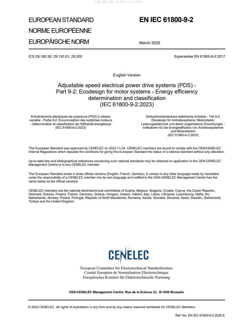
EUROPEAN STANDARD EN IEC 61800-9-2
NORME EUROPÉENNE
EUROPÄISCHE NORM March 2025
ICS 29.160.30; 29.130.01; 29.200 Supersedes EN 61800-9-2:2017
English Version
Adjustable speed electrical power drive systems (PDS) -
Part 9-2: Ecodesign for motor systems - Energy efficiency
determination and classification
(IEC 61800-9-2:2023)
Entraînements électriques de puissance (PDS) à vitesse Drehzahlveränderbare elektrische Antriebe - Teil 9-2:
variable - Partie 9-2: Écoconception des systèmes moteurs Ökodesign für Antriebssysteme, Motorstarter,
- Détermination et classification de l'efficacité énergétique Leistungselektronik und deren angetriebene Einrichtungen -
(IEC 61800-9-2:2023) Indikatoren für die Energieeffizienz von Antriebssystemen
und Motorstartern
(IEC 61800-9-2:2023)
This European Standard was approved by CENELEC on 2023-11-24. CENELEC members are bound to comply with the CEN/CENELEC
Internal Regulations which stipulate the conditions for giving this European Standard the status of a national standard without any alteration.
Up-to-date lists and bibliographical references concerning such national standards may be obtained on application to the CEN-CENELEC
Management Centre or to any CENELEC member.
This European Standard exists in three official versions (English, French, German). A version in any other language made by translation
under the responsibility of a CENELEC member into its own language and notified to the CEN-CENELEC Management Centre has the
same status as the official versions.
CENELEC members are the national electrotechnical committees of Austria, Belgium, Bulgaria, Croatia, Cyprus, the Czech Republic,
Denmark, Estonia, Finland, France, Germany, Greece, Hungary, Iceland, Ireland, Italy, Latvia, Lithuania, Luxembourg, Malta, the
Netherlands, Norway, Poland, Portugal, Republic of North Macedonia, Romania, Serbia, Slovakia, Slovenia, Spain, Sweden, Switzerland,
Türkiye and the United Kingdom.
European Committee for Electrotechnical Standardization
Comité Européen de Normalisation Electrotechnique
Europäisches Komitee für Elektrotechnische Normung
CEN-CENELEC Management Centre: Rue de la Science 23, B-1040 Brussels
© 2025 CENELEC All rights of exploitation in any form and by any means reserved worldwide for CENELEC Members.
Ref. No. EN IEC 61800-9-2:2025 E
European foreword
The text of document 22G/475/FDIS, future edition 2 of IEC 61800-9-2, prepared by SC 22G
"Adjustable speed electric power drive systems (PDS)" of IEC/TC 22 "Power electronic systems and
equipment" was submitted to the IEC-CENELEC parallel vote and approved by CENELEC as
The following dates are fixed:
• latest date by which the document has to be implemented at national (dop) 2026-03-31
level by publication of an identical national standard or by endorsement
• latest date by which the national standards conflicting with the (dow) 2028-03-31
document have to be withdrawn
This document supersedes EN 61800-9-2:2017 and all of its amendments and corrigenda (if any).
Attention is drawn to the possibility that some of the elements of this document may be the subject of
patent rights. CENELEC shall not be held responsible for identifying any or all such patent rights.
This document has been prepared under a standardization request addressed to CENELEC by the
European Commission. The Standing Committee of the EFTA States subsequently approves these
requests for its Member States.
Any feedback and questions on this document should be directed to the users’ national committee. A
complete listing of these bodies can be found on the CENELEC website.
Endorsement notice
The text of the International Standard IEC 61800-9-2:2023 was approved by CENELEC as a
European Standard without any modification.
In the official version, for Bibliography, the following notes have to be added for the standard indicated:
IEC 60034 (series) NOTE Approved as EN IEC 60034 (series)
IEC/TS 60034-25 NOTE Approved as CLC IEC/TS 60034-25
IEC 60146-1-1 NOTE Approved as EN IEC 60146-1-1
IEC 60947-4-2 NOTE Approved as EN IEC 60947-4-2
IEC 61800-1 NOTE Approved as EN IEC 61800-1
IEC 61800-2 NOTE Approved as EN IEC 61800-2
IEC 61800-3 NOTE Approved as EN IEC 61800-3
IEC 61800-5-1 NOTE Approved as EN IEC 61800-5-1
IEC 61800-9-1 NOTE Approved as EN 61800-9-1
Annex ZA
(normative)
Normative references to international publications
with their corresponding European publications
The following documents are referred to in the text in such a way that some or all of their content
constitutes requirements of this document. For dated references, only the edition cited applies. For
undated references, the latest edition of the referenced document (including any amendments)
applies.
NOTE 1 Where an International Publication has been modified by common modifications, indicated by (mod),
the relevant EN/HD applies.
NOTE 2 Up-to-date information on the latest versions of the European Standards listed in this annex is available
here: www.cencenelec.eu.
Publication Year Title EN/HD Year
IEC 60034-1 2022 Rotating electrical machines - Part 1: - -
Rating and performance
IEC 60034-2-1 2014 Rotating electrical machines - Part 2-1: EN 60034-2-1 2014
Standard methods for determining losses
and efficiency from tests (excluding
machines for traction vehicles)
IEC 60034-2-3 2020 Rotating electrical machines - Part 2-3: EN IEC 60034-2-3 2020
Specific test methods for determining
losses and efficiency of converter-fed AC
motors
IEC 60034-30-1 2014 Rotating electrical machines - Part 30-1: EN 60034-30-1 2014
Efficiency classes of line operated AC
motors (IE code)
IEC/TS 60034-30-2 2016 Rotating electrical machines - Part 30-2: CLC IEC/TS 60034- 2021
Efficiency classes of variable speed AC 30-2
motors (IE-code)
IEC/TS 60034-31 2021 Rotating electrical machines - Part 31: CLC IEC/TS 60034- 2024
Selection of energy-efficient motors 31
including variable speed applications -
Application guidelines
IEC 60038 (mod) 2009 IEC standard voltages EN 60038 2011
+ AMD1 - - -
IEC 60050-161 - International Electrotechnical Vocabulary. - -
Chapter 161: Electromagnetic
compatibility
IEC 60947-4-1 2018 Low-voltage switchgear and controlgear - EN IEC 60947-4-1 2019
Part 4-1: Contactors and motor-starters -
Electromechanical contactors and motor-
starters
Publication Year Title EN/HD Year
IEC 61000-3-12 2011 Electromagnetic compatibility (EMC) - EN 61000-3-12 2011
Part 3-12: Limits - Limits for harmonic
currents produced by equipment
connected to public low-voltage systems
with input current > 16 A and ≤ 75 A per
phase
IEC GUIDE 118 2017 Inclusion of energy efficiency aspects in - -
electrotechnical publications
IEC 61800-9-2 ®
Edition 2.0 2023-10
INTERNATIONAL
STANDARD
NORME
INTERNATIONALE
colour
inside
GROUP ENERGY EFFICIENCY PUBLICATION
PUBLICATION GROUPÉE SUR L’ÉFFICACITÉ ÉNERGÉTIQUE
Adjustable speed electrical power drive systems (PDS) –
Part 9-2: Ecodesign for motor systems – Energy efficiency determination and
classification
Entraînements électriques de puissance (PDS) à vitesse variable –
Partie 9-2: Écoconception des systèmes moteurs – Détermination et
classification de l’efficacité énergétique
INTERNATIONAL
ELECTROTECHNICAL
COMMISSION
COMMISSION
ELECTROTECHNIQUE
INTERNATIONALE
ICS 29.130.01; 29.160.30; 29.200 ISBN 978-2-8322-7576-4
– 2 – IEC 61800-9-2:2023 © IEC 2023
CONTENTS
FOREWORD . 9
INTRODUCTION . 11
1 Scope . 12
2 Normative references . 13
3 Terms, definitions and symbols. 14
3.1 Terms and definitions . 14
3.2 Symbols . 18
4 PDS efficiency, reference CDM (RCDM) and reference motor (RM) . 26
4.1 General . 26
4.2 Reference operating points of the PDS, RCDM, RM and associated losses . 27
4.3 Combining PDS losses with the driven equipment – Workflow for the semi-
analytical model (SAM) . 29
4.4 IE Classes of line-fed motors . 31
4.5 IE Classes of converter-fed motors . 31
4.6 IE Classes of frequency converters (complete drive modules, CDM) . 31
4.7 IES Classes of a PDS . 32
4.8 Consistency of IE and IES Classes . 32
4.9 Determination of the IES class of a PDS by application of "reference" and
"test" devices and guidance for the providers . 33
5 Determination of CDM, motor and PDS loss by calculation . 34
5.1 General . 34
5.2 CDM losses . 35
5.2.1 General procedure and definition of the CDM and the test load . 35
5.2.2 Overall CDM losses . 37
5.2.3 Loss determination of CDMs composed by combination of submodules . 38
5.2.4 Validation of loss calculation method . 40
5.3 Motor losses . 40
5.3.1 General . 40
5.3.2 Additional harmonic losses of three-phase asynchronous motors fed by
a CDM . 41
5.3.3 Motor loss data . 41
5.4 Power drive system (PDS) losses . 41
5.4.1 PDS losses . 41
5.4.2 PDS losses at different switching frequencies . 43
5.5 PDS losses for regenerative operation . 44
5.6 Losses of motor starters . 44
6 Limits of IE and IES Classes. 44
6.1 General . 44
6.2 CDM . 45
6.3 Correction factors for CDMs with modified functionality . 47
6.3.1 General . 47
6.3.2 Correction factors . 48
6.3.3 Reference losses and loss determination concept for CDMs and SDOMs
with multiple AC outputs . 49
6.4 Motor . 51
6.5 PDS . 51
7 Loss determination . 52
IEC 61800-9-2:2023 © IEC 2023 – 3 –
7.1 General . 52
7.2 Type testing of CDM or SDM for IE classification . 53
7.3 Type testing of PDS for IES classification . 54
7.4 Determination of losses by calculation . 54
7.4.1 CDM or SDM losses by calculation . 54
7.4.2 PDS losses by calculation . 55
7.5 Determination of losses by measurement, Input-output method . 55
7.5.1 Instrumentation . 55
7.5.2 Test conditions . 56
7.5.3 Input-output measurement of CDM losses . 57
7.5.4 Input-output measurement of SDIM losses . 59
7.5.5 Input-output measurement of SDOM losses . 61
7.5.6 Input-output measurement of PDS losses . 62
7.6 Calorimetric measurement of CDM losses . 63
7.7 Flowcharts for test procedures . 64
8 Requirements for the user’s documentation . 67
8.1 General . 67
8.2 Information for selection . 68
8.3 Information for determination of energy efficiency classification . 68
8.4 Information on the determination of additional energy losses and part load
conditions . 68
8.4.1 General . 68
8.4.2 Losses in part load conditions . 68
8.4.3 Losses of accessories and options . 69
8.4.4 Losses in stand-by mode . 69
8.4.5 Regenerative mode . 69
8.4.6 Characteristics and correction factors . 69
Annex A (informative) Losses of RCDM and example of IES class limit determination. 70
A.1 Relative loss tables . 70
A.2 Calculation of relative losses for IES classes . 71
A.2.1 General . 71
A.2.2 Determination of CDM relative losses . 71
A.2.3 Determination of motor relative losses . 72
A.2.4 Summation of PDS relative losses . 72
Annex B (informative) Description of the elements of an extended product using PDS
with regard to their impact on losses . 73
B.1 General . 73
B.2 Losses in the mains cabling and feeding section . 73
B.3 Input filter . 75
B.3.1 High frequency EMI filter . 75
B.3.2 Low frequency line harmonics filter . 75
B.4 Input converter . 76
B.4.1 General . 76
B.4.2 Diode rectifier . 76
B.4.3 Active infeed converter . 76
B.4.4 Power factor of the input converter . 78
B.4.5 Sub drive input module (SDIM) . 79
B.5 DC link . 79
B.6 Output inverter . 80
– 4 – IEC 61800-9-2:2023 © IEC 2023
B.6.1 General . 80
B.6.2 Sub drive output model (SDOM) . 81
B.7 Output filter and motor cables . 81
B.7.1 General . 81
B.7.2 Sine wave filters . 82
B.7.3 dV/dt filters and motor chokes . 83
B.7.4 High frequency EMI motor filters . 83
B.7.5 Motor cables . 83
B.8 Motor . 83
B.9 Mechanical load . 83
B.10 Control and standby losses . 84
B.11 Cooling losses . 84
B.11.1 Primary cooling losses . 84
B.11.2 Secondary cooling losses . 84
Annex C (informative) Mathematical model for CDM losses . 85
C.1 General . 85
C.2 Output inverter losses . 85
C.2.1 General . 85
C.2.2 Transistor on state losses . 85
C.2.3 Freewheeling diode on state losses . 86
C.2.4 Transistor switching losses . 86
C.2.5 Freewheeling diode switching losses . 87
C.2.6 Output inverter total losses . 88
C.3 Input converter losses . 88
C.3.1 Active infeed converter . 88
C.3.2 Diode rectifier . 88
C.4 Input choke losses . 89
C.5 DC link losses . 90
C.6 Current conductor losses . 90
C.7 Control and standby losses . 91
C.8 Cooling loss factor . 91
C.9 Other CDM losses . 91
Annex D (informative) Converter topology . 92
D.1 General . 92
D.2 Voltage source output inverter topologies different from those
mathematically described in Clause C.2 . 92
D.3 Voltage source input converter topologies different from those
mathematically described in Clause C.3 . 92
D.4 CDM topologies different from voltage source type . 93
Annex E (informative) Interpolation of motor losses and motor current . 94
E.1 General . 94
E.2 Relative and reference values . 94
E.3 Motor connections and operating ranges . 95
E.4 Interpolation of motor losses . 96
E.5 Interpolation of motor current . 99
E.6 Determination of the interpolation coefficients . 101
E.6.1 General . 101
E.6.2 Analytical determination. 101
E.6.3 Numerical determination . 103
IEC 61800-9-2:2023 © IEC 2023 – 5 –
E.7 Achievable accuracies . 104
E.8 Typical induction motor efficiency . 104
Annex F (informative) Application example for loss calculations of a CDM and a PDS . 110
F.1 General . 110
F.2 CDM loss determination . 110
F.2.1 General . 110
F.2.2 Loss determination by two-dimensional interpolation of losses of
neighbouring loss points . 111
F.2.3 Loss determination by the mathematical model described in Annex C . 114
F.3 Loss determination of the motor . 116
F.4 Loss determination of the PDS . 117
F.5 Determination of part load factors for SDIMs . 118
F.6 Application examples of reference losses and efficiency classes for modified
functionality . 119
F.6.1 General . 119
F.6.2 Example 1 – IE classification of an SDIM . 119
F.6.3 Example 2 – IE classification of an SDOM . 119
F.6.4 Example 3 – IE classification of a CDM with regenerative capability and
sinewave output filter . 120
Annex G (informative) Uncertainty of loss determination method. 122
G.1 General . 122
G.2 Calculation of uncertainty at randomly occurring errors . 122
G.3 Comparison of uncertainties for different loss determination methods . 122
Annex H (informative) Calorimetric measurement for CDM losses . 123
H.1 General . 123
H.2 Calorimeter with two chambers with air as a cooling medium . 123
H.3 Calorimeter with one chamber with air as a cooling medium . 124
H.4 Calorimeter with liquid as a cooling medium . 125
Annex I (informative) PDS loss calculation above rated speed and torque . 126
I.1 General . 126
I.2 Operating points above rated torque . 126
I.3 Operating points above rated speed . 126
I.3.1 General . 126
I.3.2 Dependency of motor losses on the CDM performance . 126
I.3.3 Dependency of CDM on the motor performance . 127
I.3.4 PDS loss calculation in the field weakening range up to 200 % of rated
speed . 127
Annex J (informative) Explanation for correction factors for the reference losses in
Table 8 . 128
J.1 General . 128
J.2 CDM . 128
J.2.1 CDM without regenerative capability . 128
J.2.2 CDM with regenerative capability . 129
J.2.3 CDM with DF ≤ 10 % . 130
U
J.2.4 CDM with a rated input voltage ≤ 250 V (three phase) . 130
J.2.5 CDM with single phase input . 130
J.3 SDIM and SDOM . 131
J.3.1 General . 131
J.3.2 SDIM without regenerative capability . 131
– 6 – IEC 61800-9-2:2023 © IEC 2023
J.3.3 SDIM with regenerative capability . 131
J.3.4 SDOM. 132
J.4 CDM, SDIM and SDOM with external cooling . 132
J.5 CDM and SDOM with multiple AC outputs . 132
Bibliography . 133
Figure 1 – Example of complete drive module (CDM) built by sub drive modules (SDM) . 15
Figure 2 – Illustration of the extended product with included motor system . 16
Figure 3 – Torque-speed-characteristic of servo PDS . 17
Figure 4 – Illustration of the operating points (shaft speed, torque) for the
determination of relative losses of the power drive system (PDS) . 28
Figure 5 – Illustration of the operating points (shaft speed, torque) for the
determination of relative losses of the reference motor (RM). 28
Figure 6 – Illustration of the operating points (relative motor stator frequency, relative
torque current) for the determination of losses of the reference complete drive module
(RCDM) . 29
Figure 7 – Illustration of the workflow to determine the energy efficiency index (EEI) of
an extended product . 30
Figure 8 – Illustration how to combine different data sources to determine the energy
efficiency index (EEI) of an extended product . 31
Figure 9 – Metrical relation . 32
Figure 10 – Guidance for CDM and motor providers for the usage of "test" and
"reference" devices to determine the IE/IES classes . 34
Figure 11 – Illustration of a typical CDM and test load . 35
Figure 12 – Example of relative losses p of the 9,95 kVA RCDM . 38
L,CDM
Figure 13 – Example of the relative power losses of PDS as function of speed and
torque . 43
Figure 14 – Example representation of the relative power losses versus switching
frequency of a 7,5 kW to 11 kW PDS . 43
Figure 15 – Example of a CDM with resistor for dissipating generated power . 44
Figure 16 – Illustration of IE Classes for a CDM . 47
Figure 17 – Topology of a CDM with multiple AC outputs . 50
Figure 18 – Losses of CDM or SDM are provided as the sum of the determined losses
plus the uncertainty of the determination method . 53
Figure 19 – Input-output measurement setup for determination of CDM losses . 58
Figure 20 – Order of CDM measurements from [1] to [8] . 58
Figure 21 – Input-output measurement setup for determination of SDIM losses . 60
Figure 22 – Input-output measurement setup for determination of SDOM losses . 61
Figure 23 – Input-output measurement setup for PDS losses . 62
Figure 24 – Order of PDS measurements from [1] to [8] . 63
Figure 25 – Calorimetric measurement setup for determining CDM losses . 64
Figure 26 – Determination of IE classification for CDM and loss determination for part
load operating points . 65
Figure 27 – Determination of IES classification for PDS and loss determination for part
load operating points . 66
Figure B.1 – Overview of the extended product and energy flow . 73
Figure B.2 – Equivalent circuit of the mains and mains cabling . 74
IEC 61800-9-2:2023 © IEC 2023 – 7 –
Figure B.3 – Illustration of a single-phase line harmonics filter . 75
Figure B.4 – PDS with a diode rectifier input converter . 76
Figure B.5 – PDS with a standard AIC input converter . 77
Figure B.6 – PDS with a F3E-AIC input converter without line choke . 77
Figure B.7 – Typical waveform of a diode rectifier line current . 78
Figure B.8 – DC link circuit . 79
Figure B.9 – DC link circuit with additional DC chokes . 80
Figure B.10 – Output inverter of the PDS . 81
Figure B.11 – Motor cable and optional output filter of the PDS . 82
Figure B.12 – Typical waveform of inverter output voltage and motor voltage when
using a sine wave output filter . 82
Figure E.1 – Normalized torque and speed of ranges a and b for connection Y or D . 95
Figure E.2 – Normalized torque and speed of ranges a and b for connection Y D . 96
Figure E.3 – Normalized torque and speed of range a for connection Y YY . 96
Figure E.4 – Normalized losses of an exemplary motor in connection Y or D . 97
Figure E.5 – Normalized losses of an exemplary motor in connection Y D . 97
Figure E.6 – Normalized losses of an exemplary motor in connection Y YY . 98
Figure E.7 – Efficiency map of the exemplary motor in connection Y or D . 98
Figure E.8 – Efficiency map of the exemplary motor in connection Y D . 99
Figure E.9 – Efficiency map of the exemplary motor in connection Y YY . 99
Figure E.10 – Line-current of the exemplary motor in connection Y or D . 100
Figure E.11 – Line-current of the exemplary motor in connection Y D . 100
Figure E.12 – Line-current of the exemplary motor in connection Y YY . 101
Figure E.13 – Standardized operating points of IEC 60034-2-3 . 102
Figure F.1 – Segments of operating points . 110
Figure F.2 – Two-dimensional interpolation . 111
Figure H.1 – One-step calorimetric measurement setup for comparative loss
measurement (CDM and heating resistor are loaded simultaneously). 123
Figure H.2 – Two-step calorimetric measurement setup for comparative loss
measurement (CDM and heating resistor are not loaded simultaneously) . 124
Figure H.3 – Liquid cooled calorimetric measurement setup for CDM loss measurement. 125
Table 1 – Minimum test load currents at different points of operation . 36
Table 2 – Test load displacement factor between fundamental output current and
fundamental output voltage at different points of operation . 36
Table 3 – Example of relative losses of the 400 V/9,95 kVA reference CDM at the
operating points described in Figure 6 . 38
Table 4 – Active SDIM power ratio to be used for loss calculation at the CDM operating
points. 40
Table 5 – Reference parameter for Formula (13). 42
Table 6 – Relative losses of the 400 V/7,5 kW PDS . 42
Table 7 – Reference CDM losses for class IE1 definition . 45
Table 8 – Correction factors for different CDM, SDIM and SDOM characteristics . 49
Table 9 – Information requirements . 67
– 8 – IEC 61800-9-2:2023 © IEC 2023
Table A.1 – Relative losses (%) of reference CDMs (IE1) at different power ratings at
the operating points described in Figure 6 . 70
Table A.2 – Relative losses of the 9,95 kVA CDM according to Table A.1 . 71
Table B.1 – Typical values of λ for different input converter topologies . 78
Table C.1 – Reference parameters for Formula (C.1) . 85
Table C.2 – Variables for Formula (C.1) . 86
Table C.3 – Reference parameters for Formula (C.2) . 86
Table C.4 – Reference parameters for Formula (C.3) . 87
Table C.5 – Reference parameters for Formula (C.4) . 87
Table C.6 – Reference parameters for Formula (C.6) . 89
Table C.7 – Variables for Formula (C.6) . 89
Table C.8 – Reference parameters for Formula (C.7) . 89
Table C.9 – Reference parameters for Formula (C.8) . 90
Table C.10 – Reference parameters for Formula (C.9) . 90
Table C.11 – Reference parameter for Formula (5) . 91
Table C.12 – Reference parameter for Formula (C.10) . 91
Table E.1 – Normative operating points of IEC 60034-2-3 . 101
Table E.2 – Interpolation coefficients of typical 4-pole IE2 induction machines . 105
Table E.3 – Interpolation coefficients of typical 2-pole IE2 induction machines . 106
Table E.4 – Interpolation coefficients of typical 4-pole IE3 induction machines . 107
Table E.5 – Interpolation coefficients of typical 4-pole IE4 induction machines . 108
Table E.6 – Interpolation coefficients of typical 4-pole IE5 induction machines . 109
Table F.1 – Relative losses of a 400 V/9,95 kVA example CDM (IE1) at the predefined
operating points
...