


EN 50104:2019
(Main)Electrical equipment for the detection and measurement of oxygen - Performance requirements and test methods
General Information
- Abstract
This document specifies general requirements for design, testing and performance, and describes the test methods that apply to portable, transportable and fixed equipment for the measurement of the oxygen concentration in gas mixtures indicating up to 25 % (v/v). The equipment, or parts thereof, may be intended for use in explosive atmospheres (see 4.1) and in mines susceptible to firedamp. This document applies to equipment intended for monitoring oxygen deficiency and enrichment. EXAMPLE Monitoring oxygen deficiency and/or enrichment includes: - protection of human health and safety in potentially oxygen deficient atmospheres; - fire protection by monitoring areas with reduced oxygen concentration; - fire protection by monitoring oxygen concentrations exceeding that of normal ambient air. This document also applies to equipment with an oxygen measuring function for explosion protection in the case of monitoring inertisation. NOTE 1 Inertisation is an explosion protection technique where a potentially explosive atmosphere is purged with inert gas. NOTE 2 Commonly used oxygen sensors in commercial equipment for industrial application are: - electrochemical sensors (aqueous and solid electrolytes); - paramagnetic sensors; - zirconium dioxide sensors; - tunable diode laser absorption spectroscopy sensors (TDLAS). This document is applicable to equipment intended to measure reliably the oxygen concentration, to provide an indication, alarm or other output function, the purpose of which is to give a warning of a potential hazard and, in some cases, to initiate automatic or manual protective action(s), whenever the level exceeds or falls below an alarm set point. This document is applicable to equipment, including integral sampling systems of aspirated equipment, intended to be used for commercial, industrial and non-residential safety applications. This document does not apply to external sampling systems, or to equipment of laboratory or scientific type, or to medical equipment, or to equipment used only for process monitoring and/or control purposes. For equipment used for sensing the presence of multiple gases, this document applies only to the measurement of oxygen. This document is also applicable to equipment using optical principles (e.g. TDLAS), where the optical transmitter and receiver or the optical transceiver (i.e. combined transmitter and receiver) and a suitable reflector are not located in a common enclosure. However, in this case it will be necessary to modify the test conditions described in Clause 5.3 and to introduce supplementary tests to Clause 5.4 of this document. Such supplementary tests will include alignment, beam block fault, long range operation. Guidance to appropriate modification of the test conditions and supplementary tests can be taken from EN 60079 29 4. Modifications of the test conditions as well as modified and supplementary tests are expected to be agreed between the manufacturer and test laboratory and identified and described in the test report.
- Status
- Published
- Publication Date
- 31-Oct-2019
- Withdrawal Date
- 25-Aug-2022
- Current Stage
- 6060 - Document made available - Publishing
- Start Date
- 01-Nov-2019
- Due Date
- 02-Mar-2020
- Completion Date
- 01-Nov-2019
- Directive
- Harmonized Standard2014/34/EU - Directive 2014/34/EU Of The European Parliament And Of The Council of 26 February 2014 on the harmonisation of the laws of the Member States relating to equipment and protective systems intended for use in potentially explosive atmospheres (recast)OJ Ref: OJ L 194 OJ Date: 02-Aug-2023



Overview - EN 50104:2019 (Electrical equipment for oxygen detection and measurement)
EN 50104:2019 (CLC/CENELEC) sets out performance requirements and test methods for electrical equipment that detects and measures oxygen in gas mixtures (indicating up to 25 % v/v). It applies to portable, transportable and fixed oxygen measurement and monitoring equipment used for safety‑related applications, including devices intended for use in explosive atmospheres and mines. The standard covers devices that provide indication, alarm or other outputs to warn of oxygen deficiency or enrichment and to support protective actions (including inertisation monitoring).
Key topics and technical requirements
- Scope and applicability
- Equipment types: portable, transportable, fixed, aspirated and diffusion devices.
- Exclusions: laboratory/scientific equipment, medical devices, external sampling systems, and equipment intended solely for process control.
- Sensor technologies covered
- Electrochemical (aqueous and solid electrolyte), paramagnetic, zirconium dioxide, and optical methods such as TDLAS.
- Design and functional requirements
- Indication, alarm signals, fault signals, adjustments and labelling requirements.
- Requirements for battery‑powered equipment, transmitters, and separate control units.
- Considerations for equipment using software and digital technologies.
- Performance and environmental tests
- Calibration curve, repeatability and stability tests.
- Alarm set‑point verification, time of response and warm‑up time.
- Environmental stress tests: temperature, pressure, humidity, air velocity, vibration, drop tests and flow‑rate effects.
- Electromagnetic compatibility (EMC) and power‑supply variation tests.
- Tests for poisoning/interfering gases, field calibration kits and battery capacity checks.
- Special cases
- Guidance for optical systems (e.g. TDLAS) where transmitter and receiver are separated - requires modified/supplementary tests (alignment, beam-block faults, long‑range operation) with reference to EN 60079‑29‑4.
- Documentation
- Labelling, marking and instruction manual content that supports safe use and compliance.
Practical applications and users
- Who uses EN 50104: manufacturers of oxygen detectors and sensors, test laboratories, system integrators, safety engineers, facility managers in industrial, commercial and non‑residential settings, and organizations operating in explosive atmospheres or mines.
- Typical applications: personnel safety monitoring (oxygen deficiency/enrichment), fire protection (low or elevated O2 monitoring), explosion prevention via inertisation monitoring, and fixed-point or portable safety instrumentation in chemical plants, refineries, confined spaces, warehouses and mines.
Related standards
- EN 50270 - EMC for gas detection apparatus
- EN 50271 - Requirements for apparatus using software/digital technologies
- EN 60079‑29‑2 / EN 60079‑29‑4 - Gas detector selection/TDLAS guidance (explosive atmospheres)
Keywords: EN 50104:2019, oxygen detection, oxygen measurement, gas detectors, TDLAS, electrochemical sensors, zirconium dioxide, performance requirements, test methods, explosive atmospheres.
Relations
- Effective Date
- 07-Jun-2022
- Effective Date
- 30-Dec-2025
- Effective Date
- 14-Sep-2021
Get Certified
Connect with accredited certification bodies for this standard

CIS Institut d.o.o.
Personal Protective Equipment (PPE) certification body. Notified Body NB-2890 for EU Regulation 2016/425 PPE.

Kiwa BDA Testing
Building and construction product certification.
Kmetijski inštitut Slovenije
Agricultural Institute of Slovenia. Soil testing, plant health, agricultural product analysis.
Sponsored listings
Frequently Asked Questions
EN 50104:2019 is a standard published by CLC. Its full title is "Electrical equipment for the detection and measurement of oxygen - Performance requirements and test methods". This standard covers: This document specifies general requirements for design, testing and performance, and describes the test methods that apply to portable, transportable and fixed equipment for the measurement of the oxygen concentration in gas mixtures indicating up to 25 % (v/v). The equipment, or parts thereof, may be intended for use in explosive atmospheres (see 4.1) and in mines susceptible to firedamp. This document applies to equipment intended for monitoring oxygen deficiency and enrichment. EXAMPLE Monitoring oxygen deficiency and/or enrichment includes: - protection of human health and safety in potentially oxygen deficient atmospheres; - fire protection by monitoring areas with reduced oxygen concentration; - fire protection by monitoring oxygen concentrations exceeding that of normal ambient air. This document also applies to equipment with an oxygen measuring function for explosion protection in the case of monitoring inertisation. NOTE 1 Inertisation is an explosion protection technique where a potentially explosive atmosphere is purged with inert gas. NOTE 2 Commonly used oxygen sensors in commercial equipment for industrial application are: - electrochemical sensors (aqueous and solid electrolytes); - paramagnetic sensors; - zirconium dioxide sensors; - tunable diode laser absorption spectroscopy sensors (TDLAS). This document is applicable to equipment intended to measure reliably the oxygen concentration, to provide an indication, alarm or other output function, the purpose of which is to give a warning of a potential hazard and, in some cases, to initiate automatic or manual protective action(s), whenever the level exceeds or falls below an alarm set point. This document is applicable to equipment, including integral sampling systems of aspirated equipment, intended to be used for commercial, industrial and non-residential safety applications. This document does not apply to external sampling systems, or to equipment of laboratory or scientific type, or to medical equipment, or to equipment used only for process monitoring and/or control purposes. For equipment used for sensing the presence of multiple gases, this document applies only to the measurement of oxygen. This document is also applicable to equipment using optical principles (e.g. TDLAS), where the optical transmitter and receiver or the optical transceiver (i.e. combined transmitter and receiver) and a suitable reflector are not located in a common enclosure. However, in this case it will be necessary to modify the test conditions described in Clause 5.3 and to introduce supplementary tests to Clause 5.4 of this document. Such supplementary tests will include alignment, beam block fault, long range operation. Guidance to appropriate modification of the test conditions and supplementary tests can be taken from EN 60079 29 4. Modifications of the test conditions as well as modified and supplementary tests are expected to be agreed between the manufacturer and test laboratory and identified and described in the test report.
This document specifies general requirements for design, testing and performance, and describes the test methods that apply to portable, transportable and fixed equipment for the measurement of the oxygen concentration in gas mixtures indicating up to 25 % (v/v). The equipment, or parts thereof, may be intended for use in explosive atmospheres (see 4.1) and in mines susceptible to firedamp. This document applies to equipment intended for monitoring oxygen deficiency and enrichment. EXAMPLE Monitoring oxygen deficiency and/or enrichment includes: - protection of human health and safety in potentially oxygen deficient atmospheres; - fire protection by monitoring areas with reduced oxygen concentration; - fire protection by monitoring oxygen concentrations exceeding that of normal ambient air. This document also applies to equipment with an oxygen measuring function for explosion protection in the case of monitoring inertisation. NOTE 1 Inertisation is an explosion protection technique where a potentially explosive atmosphere is purged with inert gas. NOTE 2 Commonly used oxygen sensors in commercial equipment for industrial application are: - electrochemical sensors (aqueous and solid electrolytes); - paramagnetic sensors; - zirconium dioxide sensors; - tunable diode laser absorption spectroscopy sensors (TDLAS). This document is applicable to equipment intended to measure reliably the oxygen concentration, to provide an indication, alarm or other output function, the purpose of which is to give a warning of a potential hazard and, in some cases, to initiate automatic or manual protective action(s), whenever the level exceeds or falls below an alarm set point. This document is applicable to equipment, including integral sampling systems of aspirated equipment, intended to be used for commercial, industrial and non-residential safety applications. This document does not apply to external sampling systems, or to equipment of laboratory or scientific type, or to medical equipment, or to equipment used only for process monitoring and/or control purposes. For equipment used for sensing the presence of multiple gases, this document applies only to the measurement of oxygen. This document is also applicable to equipment using optical principles (e.g. TDLAS), where the optical transmitter and receiver or the optical transceiver (i.e. combined transmitter and receiver) and a suitable reflector are not located in a common enclosure. However, in this case it will be necessary to modify the test conditions described in Clause 5.3 and to introduce supplementary tests to Clause 5.4 of this document. Such supplementary tests will include alignment, beam block fault, long range operation. Guidance to appropriate modification of the test conditions and supplementary tests can be taken from EN 60079 29 4. Modifications of the test conditions as well as modified and supplementary tests are expected to be agreed between the manufacturer and test laboratory and identified and described in the test report.
EN 50104:2019 is classified under the following ICS (International Classification for Standards) categories: 13.320 - Alarm and warning systems. The ICS classification helps identify the subject area and facilitates finding related standards.
EN 50104:2019 has the following relationships with other standards: It is inter standard links to EN 50104:2010, EN IEC 60079-29-0:2026, EN 50104:2019/A1:2023. Understanding these relationships helps ensure you are using the most current and applicable version of the standard.
EN 50104:2019 is associated with the following European legislation: EU Directives/Regulations: 2014/34/EU; Standardization Mandates: M/BC/CEN/92/46. When a standard is cited in the Official Journal of the European Union, products manufactured in conformity with it benefit from a presumption of conformity with the essential requirements of the corresponding EU directive or regulation.
EN 50104:2019 is available in PDF format for immediate download after purchase. The document can be added to your cart and obtained through the secure checkout process. Digital delivery ensures instant access to the complete standard document.
Standards Content (Sample)
SLOVENSKI STANDARD
01-februar-2020
Nadomešča:
SIST EN 50104:2010
Električne naprave za odkrivanje in merjenje kisika - Zahteve za delovanje in
preskusne metode
Electrical apparatus for the detection and measurement of oxygen - Performance
requirements and test methods
Elektrische Geräte für die Detektion und Messung von Sauerstoff - Anforderungen an
das Betriebsverhalten und Prüfverfahren
Appareils électriques de détection et de mesure de l'oxygène - Exigences d’aptitude à la
fonction et méthodes d’essai
Ta slovenski standard je istoveten z: EN 50104:2019
ICS:
13.320 Alarmni in opozorilni sistemi Alarm and warning systems
29.260.20 Električni aparati za Electrical apparatus for
eksplozivna ozračja explosive atmospheres
2003-01.Slovenski inštitut za standardizacijo. Razmnoževanje celote ali delov tega standarda ni dovoljeno.
EUROPEAN STANDARD
EN 50104
NORME EUROPÉENNE
EUROPÄISCHE NORM
November 2019
ICS 13.320 Supersedes EN 50104:2010 and all of its amendments
and corrigenda (if any)
English Version
Electrical equipment for the detection and measurement of
oxygen - Performance requirements and test methods
Appareils électriques de détection et de mesure de Elektrische Geräte für die Detektion und Messung von
l'oxygène - Exigences d'aptitude à la fonction et méthodes Sauerstoff - Anforderungen an das Betriebsverhalten und
d'essai Prüfverfahren
This European Standard was approved by CENELEC on 2019-08-26. CENELEC members are bound to comply with the CEN/CENELEC
Internal Regulations which stipulate the conditions for giving this European Standard the status of a national standard without any
alteration.
Up-to-date lists and bibliographical references concerning such national standards may be obtained on application to the CEN-CENELEC
Management Centre or to any CENELEC member.
This European Standard exists in three official versions (English, French, German). A version in any other language made by translation
under the responsibility of a CENELEC member into its own language and notified to the CEN-CENELEC Management Centre has the
same status as the official versions.
CENELEC members are the national electrotechnical committees of Austria, Belgium, Bulgaria, Croatia, Cyprus, the Czech Republic,
Denmark, Estonia, Finland, France, Germany, Greece, Hungary, Iceland, Ireland, Italy, Latvia, Lithuania, Luxembourg, Malta, the
Netherlands, Norway, Poland, Portugal, Republic of North Macedonia, Romania, Serbia, Slovakia, Slovenia, Spain, Sweden, Switzerland,
Turkey and the United Kingdom.
European Committee for Electrotechnical Standardization
Comité Européen de Normalisation Electrotechnique
Europäisches Komitee für Elektrotechnische Normung
CEN-CENELEC Management Centre: Rue de la Science 23, B-1040 Brussels
© 2019 CENELEC All rights of exploitation in any form and by any means reserved worldwide for CENELEC Members.
Ref. No. EN 50104:2019 E
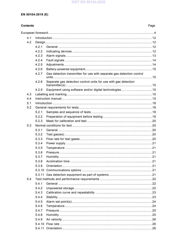
Contents Page
European foreword . 4
4.1 Introduction . 12
4.2 Design . 12
4.2.1 General . 12
4.2.2 Indicating devices . 12
4.2.3 Alarm signals . 13
4.2.4 Fault signals . 14
4.2.5 Adjustments . 14
4.2.6 Battery-powered equipment . 15
4.2.7 Gas detection transmitter for use with separate gas detection control
units . 15
4.2.8 Separate gas detection control units for use with gas detection
transmitter(s) . 15
4.2.9 Equipment using software and/or digital technologies . 15
4.3 Labelling and marking . 15
4.4 Instruction manual . 15
5.1 Introduction . 18
5.2 General requirements for tests . 18
5.2.1 Samples and sequence of tests . 18
5.2.2 Preparation of equipment before testing . 19
5.2.3 Mask for calibration and test . 20
5.3 Normal conditions for test . 20
5.3.1 General . 20
5.3.2 Test gas(es) . 20
5.3.3 Flow rate for test gases . 20
5.3.4 Power supply . 21
5.3.5 Temperature . 21
5.3.6 Pressure . 21
5.3.7 Humidity . 21
5.3.8 Acclimation time . 21
5.3.9 Orientation . 21
5.3.10 Communications options . 21
5.3.11 Gas detection equipment as part of systems . 21
5.4 Test methods and performance requirements . 22
5.4.1 General . 22
5.4.2 Unpowered storage . 22
5.4.3 Calibration curve and repeatability . 23
5.4.4 Stability . 23
5.4.5 Alarm set-point(s) . 24
5.4.6 Temperature . 24
5.4.7 Pressure . 25
5.4.8 Humidity . 25
5.4.9 Air velocity . 26
5.4.10 Flow rate . 26
5.4.11 Orientation . 26
5.4.12 Vibration . 27
5.4.13 Drop test. 28
5.4.14 Warm-up time . 29
5.4.15 Time of response . 29
5.4.16 Battery capacity . 29
5.4.17 Power supply variations . 30
5.4.18 Electromagnetic compatibility . 30
5.4.19 Addition of sampling probe . 30
5.4.20 Poisons and other gases . 31
5.4.21 Field calibration kit . 31
5.4.22 Operation at or below the lower limit of the measuring range . 31
5.4.23 Verification of software and digital components . 32
Annex A (informative) Significant changes between this edition and EN 50104:2010 . 33
Annex ZZ (informative) Relationship between this European standard and the essential
requirements of Directive 2014/34/EU aimed to be covered . 36
Table ZZ.1 — Correspondence between this European standard and Annex II of Directive
2014/34/EU . 36
Bibliography . 37
European foreword
This document (EN 50104:2019) has been prepared by CLC/TC 31, “Electrical apparatus for potentially
explosive atmospheres”.
The following dates are fixed:
• latest date by which this document has (dop) 2020-08-26
to be implemented at national level by
publication of an identical national
standard or by endorsement
• latest date by which the national (dow) 2022-08-26
standards conflicting with this document
have to be withdrawn
This document supersedes EN 50104:2010 and all of its amendments and corrigenda (if any).
The State of the Art is included in Annex A “Significant changes between this edition and EN 50104:2010”
which lists all changes to EN 50104:2010.
Attention is drawn to the possibility that some of the elements of this document may be the subject of
patent rights. CENELEC shall not be held responsible for identifying any or all such patent rights.
This document has been prepared under a mandate given to CENELEC by the European Commission
and the European Free Trade Association and covers essential requirements of EU Directive 2014/34/EU.
For the relationship with EU Directive(s), see informative Annex ZZ, which is an integral part of this
document.
1 Scope
This document specifies general requirements for design, testing and performance, and describes the test
methods that apply to portable, transportable and fixed equipment for the measurement of the oxygen
concentration in gas mixtures indicating up to 25 % (v/v). The equipment, or parts thereof, may be
intended for use in explosive atmospheres (see 4.1) and in mines susceptible to firedamp.
This document applies to equipment intended for monitoring oxygen deficiency and enrichment.
EXAMPLE Monitoring oxygen deficiency and/or enrichment includes:
— protection of human health and safety in potentially oxygen deficient atmospheres;
— fire protection by monitoring areas with reduced oxygen concentration;
— fire protection by monitoring oxygen concentrations exceeding that of normal ambient air.
This document also applies to equipment with an oxygen measuring function for explosion protection in
the case of monitoring inertisation.
NOTE 1 Inertisation is an explosion protection technique where a potentially explosive atmosphere is purged with
inert gas.
NOTE 2 Commonly used oxygen sensors in commercial equipment for industrial application are:
— electrochemical sensors (aqueous and solid electrolytes);
— paramagnetic sensors;
— zirconium dioxide sensors;
— tunable diode laser absorption spectroscopy sensors (TDLAS).
This document is applicable to equipment intended to measure reliably the oxygen concentration, to
provide an indication, alarm or other output function, the purpose of which is to give a warning of a
potential hazard and, in some cases, to initiate automatic or manual protective action(s), whenever the
level exceeds or falls below an alarm set point.
This document is applicable to equipment, including integral sampling systems of aspirated equipment,
intended to be used for commercial, industrial and non-residential safety applications.
This document does not apply to external sampling systems, or to equipment of laboratory or scientific
type, or to medical equipment, or to equipment used only for process monitoring and/or control purposes.
For equipment used for sensing the presence of multiple gases, this document applies only to the
measurement of oxygen.
This document is also applicable to equipment using optical principles (e.g. TDLAS), where the optical
transmitter and receiver or the optical transceiver (i.e. combined transmitter and receiver) and a suitable
reflector are not located in a common enclosure. However, in this case it will be necessary to modify the
test conditions described in Clause 5.3 and to introduce supplementary tests to Clause 5.4 of this
document. Such supplementary tests will include alignment, beam block fault, long range operation.
Guidance to appropriate modification of the test conditions and supplementary tests can be taken from
EN 60079-29-4. Modifications of the test conditions as well as modified and supplementary tests are
expected to be agreed between the manufacturer and test laboratory and identified and described in the
test report.
2 Normative references
The following documents are referred to in the text in such a way that some or all of their content
constitutes requirements of this document. For dated references, only the edition cited applies. For
undated references, the latest edition of the referenced document (including any amendments) applies.
EN 50270, Electromagnetic compatibility - Electrical apparatus for the detection and measurement of
combustible gases, toxic gases or oxygen
EN 50271, Electrical apparatus for the detection and measurement of combustible gases, toxic gases or
oxygen - Requirements and tests for apparatus using software and/or digital technologies
EN 60068-2-6, Environmental testing - Part 2-6: Tests - Test Fc: Vibration (sinusoidal)
EN 60079-29-2, Explosive atmospheres - Part 29-2: Gas detectors - Selection, installation, use and
maintenance of detectors for flammable gases and oxygen
3 Terms and definitions
For the purposes of this document, the following terms and definitions apply.
ISO and IEC maintain terminological databases for use in standardization at the following addresses:
• IEC Electropedia: available at http://www.electropedia.org/
• ISO Online browsing platform: available at http://www.iso.org/obp
3.1 Gas properties
3.1.1
ambient air
normal atmosphere surrounding the equipment
3.1.2
poison
substance that lead to temporary or permanent change of performance,
particularly loss of sensitivity of the sensing element
3.1.3
reference air
air, under normal ambient conditions, with an oxygen concentration of (21 ± 0,4) % (v/v)
3.1.4
standard test gas
test gas with a composition specified for each item of equipment to be used for all tests unless otherwise
stated
3.1.5
volume fraction
v/v
quotient of the volume of a specified component and the sum of the volumes of all components of a gas
mixture before mixing, all volumes referring to the pressure and the temperature of the gas mixture
Note 1 to entry: The volume fraction and volume concentration take the same value if, at the same state
conditions, the sum of the component volumes before mixing and the volume of the mixture are equal. However,
because the mixing of two or more gases at the same state conditions is usually accompanied by a slight contraction
or, less frequently, a slight expansion, this is not generally the case.
3.1.6
zero test gas
gas, such as nitrogen, which is free of oxygen, and interfering and contaminating substances
3.2 Types of equipment
3.2.1
alarm-only equipment
equipment with an alarm but not having an indication of measured value
3.2.2
aspirated equipment
equipment that samples the gas by drawing it to the gas sensor
Note 1 to entry: A hand operated or electric pump is often used to draw gas to the sensor.
3.2.3
automatically aspirated equipment
aspirated equipment with an integral pump or separate pump, which is connected directly to the
equipment
3.2.4
continuous duty equipment
equipment that is powered for long periods of time, but may have either continuous or intermittent sensing
Note 1 to entry: Within this document, all equipment is regarded as continuous duty.
3.2.5
diffusion equipment
equipment in which the transfer of gas from the atmosphere to the sensor takes place without aspirated
flow
3.2.6
fixed equipment
equipment fastened to a support, or otherwise secured in a specific location when energized
3.2.7
portable equipment
equipment intended to be carried by a person during operation
Note 1 to entry: Portable equipment is battery powered and includes, but is not limited to
a) hand-held equipment, typically less than 1 kg, which requires use of only one hand to operate,
b) personal monitors, similar in size and mass to the hand-held equipment, that are continuously operating (but not
necessarily continuously sensing) while they are attached to the user, and
c) larger equipment that can be operated by the user while it is carried either by hand, by a shoulder strap or carrying
harness and which may or may not have a hand directed probe.
3.2.8
transportable equipment
equipment not intended to be carried by a person during operation, nor intended for fixed installation
3.2.9
gas detection transmitter
fixed gas detection equipment that provide a conditioned electronic signal or output indication to a
generally accepted industry standard (such as 4-20 mA), intended to be utilized with separate gas
detection control units, or signal processing data acquisition, central monitoring and similar systems which
typically process information from various locations and sources including, but not limited to, gas detection
equipment
3.2.10
gas detection control unit
equipment intended to provide indications on a display, alarm functions, output contacts and/or alarm
signal outputs or any combinations when operated with remote sensor(s)
3.2.11
separate gas detection control unit
equipment intended to provide indications on a display, alarm functions, output contacts and/or alarm
signal outputs or any combination when operated with gas detection transmitter(s)
3.2.12
equipment with integral sensor(s)
equipment that provides indications on a display, alarm functions, output contacts and/or alarm signal
outputs using a sensor which is within or directly mounted to the equipment housing
3.2.13
accessory
component which can be fitted to the equipment for special purpose
EXAMPLE External gas pump, sampling probe, hoses, collecting cone, weather protection device
3.3 Sensors
3.3.1
sensing element
part of the sensor which is sensitive to the gas/vapour to be measured
3.3.2
sensor
assembly in which the sensing element is housed and that may also contain associated circuit
components
3.3.3
integral sensor
sensor which is within or directly assembled to the equipment housing
3.3.4
remote sensor
sensor which is installed separately, but is electrically connected to a gas detection control unit, gas
detection transmitter, or to transportable or portable equipment
3.3.5
measuring principle
type of physical or physico-chemical detection principle and the measurement procedure to determine the
measured value
3.4 Supply of gas to equipment
3.4.1
sample line
means by which the gas being sampled is conveyed to the sensor
Note 1 to entry: Accessories such as filter or water trap are often included in the sample line.
3.4.2
sampling probe
separate accessory sample line which is optionally attached to the equipment
Note 1 to entry: It is usually short (e.g. of the order of 1 m) and rigid, although it can be telescopic. In some cases it
is connected by a flexible tube to the equipment.
3.4.3
field calibration kit
means of presenting test gas to the equipment for the purpose of calibrating/adjusting or verifying the
operation of the equipment
Note 1 to entry: The field calibration kit can be used for verifying the operation of the alarms if the concentration of
the test gas is beyond the alarm set-point.
Note 2 to entry: A mask for calibration and test (see 3.4.4) is an example of a field calibration kit.
3.4.4
mask for calibration and test
device that can be attached to the equipment to present a test gas to the sensor in a reproducible manner
3.5 Signals and alarms
3.5.1
alarm set point
setting of the equipment at which the measured concentration will cause the equipment to initiate an
indication, alarm or other output function
3.5.2
latching alarm
alarm that, once activated, requires deliberate action to be deactivated
3.5.3
fault signal
audible, visible or other type of output, different from the alarm signal, permitting, directly or indirectly, a
warning or indication that the equipment is not working satisfactorily
3.5.4
repeatability
closeness of agreement between the results of successive measurements of the same measurand,
carried out under the same conditions of measurement, i.e.:
— by the same measurement procedure,
— by the same observer,
— with the same measuring instruments, used under the same conditions,
— in the same laboratory,
— at relatively short intervals of time.
3.5.5
special state
any state of the equipment other than those in which monitoring of gas concentration and/or alarming is
the intent
Note 1 to entry: Special state includes warm-up, calibration mode or fault condition.
3.5.6
measured value
calculated oxygen concentration that results from processing the sensor signal
Note 1 to entry: The measured value may be further processed before indication on output or display (e.g.
suppression of indication).
3.5.7
indication
representation of the measured value on an output or display
Note 1 to entry: The indication may be affected by suppression or filtering of the measured value.
3.6 Times
3.6.1
drift
variation in the equipment indication with time, at any fixed gas volume fraction under constant ambient
conditions
3.6.2
final indication
indication given by the equipment after stabilisation
3.6.3
stabilisation
state when three successive readings of an equipment at a constant gas volume fraction, taken at 2 min
intervals or twice the respective t(90), whichever is less, indicates no changes greater than ±1 % of the
measuring range
3.6.4
time of response
t(x)
time interval, with the equipment in a warmed-up condition, between the time when an instantaneous
variation in volume fraction is produced at the equipment inlet and the time when the response reaches a
stated percentage (x) of the difference between the initial and the final indication
3.6.5
warm-up time
time interval, with the equipment in a stated atmosphere, between the time when the equipment is
switched on and the time when the indication reaches and remains within the stated tolerances
Note 1 to entry: see Figure 1
Key
1 Indication
2 Power off in reference air or in zero test gas
3 Power on in reference air or in zero test gas
4 Indication of 20,9 % (v/v) of oxygen or indication of zero test gas
5 Warm-up time
6 Specified tolerance band of indication in reference air or zero test gas
7 Time
Figure 1 — Warm-up time in reference air or in zero test gas (typical)
3.7 Miscellaneous
3.7.1
special tool
tool required to gain access to or, to adjust the equipment controls or required to replace the sensor
Note 1 to entry: The design of the tool is intended to discourage unauthorised interference with the equipment.
3.7.2
calibration
procedure which establishes the relationship between a measured value and the concentration of a test
gas
Note 1 to entry: If the deviation at calibration is too high, usually an adjustment will be carried out subsequently.
3.7.3
adjustment
procedure carried out to minimize the deviation of the measured value from the test gas concentration
Note 1 to entry: When the equipment is adjusted to give an indication of zero in nitrogen, the procedure is called
’zero adjustment’.
4 General requirements
4.1 Introduction
In addition, parts of the gas detection equipment intended for use in explosive atmospheres shall employ
materials, and should comply with the construction and explosion protection as specified in the
appropriate regulations for explosion protection. The ambient temperature and pressure ranges of such
equipment conforming to this document shall not exceed the ambient temperature and pressure ranges of
the Type(s) of Protection.
4.2 Design
4.2.1 General
Gas detection equipment or parts thereof (e.g. remote sensors) specifically intended for use in the
presence of corrosive vapours or gases shall be constructed of materials known to be resistant to
corrosion by such substances.
The equipment shall be constructed in such a manner that regular functional checks can be easily
undertaken by the user and that it can be equipped with suitable devices for application of test gas (field
calibration kit).
All materials and components used in the construction of the equipment shall be used within the
manufacturer’s ratings or limitations unless otherwise specified by appropriate safety standards.
For aspirated equipment, inlet and outlet ports shall be unambiguously marked to ensure the correct
connection of any sample and exhaust lines.
Any malfunction of outputs from the gas detection equipment not relevant to safety or health shall not
adversely affect the functions of the equipment related to safety.
EXAMPLE Equipment with 4–20mA and Highway Addressable Remote Transducer (HART) Protocol
communication where only the 4–20 mA communication is defined in the instruction manual as related to safety. The
loss of HART communication is not related to safety.
4.2.2 Indicating devices
4.2.2.1 Indicators
Readily distinguishable indicators shall be provided to show that the equipment is energized, in alarm and
in a special state.
Portable equipment shall provide visual and audible indicators for both fault and alarms. The special state
“warm-up” shall be indicated by a visual and/or audible signal. The special states “calibration mode” and
“parameterization mode” shall be indicated by a visual signal.
Transportable or fixed equipment shall provide visual indicators for power, special states and for alarm
states. It is permitted for fixed equipment that the indications related to gas detection transmitters and
remote sensors are shown only at the (separate) gas detection control unit.
If audible indicators are provided for transportable or fixed equipment, alarms are required as a minimum.
If the equipment has more than one measuring range, the range selected shall be clearly identified.
4.2.2.2 Display and other devices for indication of measured values
For equipment with a display to indicate gas concentrations, the gas type, gas concentration and unit of
measurement shall be indicated. It is permissible to mark the gas and unit of measurement adjacent to
the display.
Within the measuring range, the resolution of the display and all other devices for indication of the
measured value shall be at least 1 % of the upper limit of the measuring range or 0,1 % (v/v) of oxygen,
whichever is smaller.
All devices for indication of the measured value shall present the same value within the resolution of each
device.
Any over-range measurements shall be clearly indicated.
For alarm-only equipment, the manufacturer shall identify suitable points for connecting indicating or
recording devices for the purpose of testing the compliance of the equipment with this document.
4.2.2.3 Suppression of indication and measured values below zero
It shall be possible to configure the equipment such that in measuring mode any kind of suppression of
the measured value is permanently disabled. In calibration mode any kind of suppression of the measured
value shall be automatically disabled.
Measured values within the measuring range shall be indicated. Suppression of indication is only
permitted according to the rules below.
Measured values below 2 % of the upper limit of the measuring range (values below zero included) shall
be indicated as:
a) zero,
b) another indication that the measured value is below 2 % of the upper limit of the measuring range or
c) the measured value.
All equipment shall indicate measured values below −2 % of the upper limit of the measuring range or
shall provide a fault signal. The equipment shall provide a fault signal prior to measured values below
−5 % of the upper limit of the measuring range.
Measured values within an interval of ± 0,5 % (v/v) of oxygen around the indication in reference air shall
be indicated as:
a) the indication in reference air,
b) the measured value.
4.2.2.4 Indicator light
If only one indicator light is provided for signalling alarms, special states and other indications, it shall be
coloured red. If separate indicator lights are used or if a multi-coloured indicator light is provided, the
colours shall be used in the following order of priority ((a) being highest priority):
a) alarms indicating the presence of gas beyond an alarm set point shall be coloured RED;
b) equipment special state indicators shall be coloured YELLOW;
c) power supply indicators shall be coloured GREEN.
If a multi-coloured indicator light is provided, the equipment shall provide an additional indication by means
other than colour.
If there is more than one indicator light of the same colour with different functions, the lights shall be
labelled to show their functions. Text, marks and icons on a screen display describing the indicator lights
are permissible in place of printed labels.
4.2.3 Alarm signals
4.2.3.1 Alarm settings
The audible and visual alarm settings for the equipment shall not be ambiguous.
Alarm set points shall not be adjustable outside the measuring range.
4.2.3.2 Alarm output functions
It is permitted that alarms are configurable to be latching or non-latching.
If alarms are not configurable to be latching or non-latching, the alarm with the highest relevance for
safety for each direction (activation at increasing or decreasing oxygen concentration, respectively) shall
be latching.
If alarms are configurable to be latching or non-latching, the alarm with the highest relevance for safety for
each direction (activation at increasing or decreasing oxygen concentration, respectively) shall be
configured latching as a factory default setting.
NOTE The factory setting at delivery can deviate from the factory default setting on user request.
Alarms shall remain in operation while the alarm condition is still present although an audible alarm may
be silenced if this audible alarm is not the only alarm.
If it is possible to de-activate alarm devices, output contacts or alarm signal outputs, this deactivation shall
be indicated by a signal. For fixed equipment, this shall include a contact or other transmittable output
signal. The output signal or contacts are not required if the alarms are automatically re-enabled within 15
min.
EXAMPLE It might be necessary to de-activate alarm devices for calibration purposes.
4.2.4 Fault signals
Externally powered equipment shall provide a fault signal in the event of failure of power to the equipment.
Externally powered equipment shall provide a fault signal when the supply voltage falls below the lower
supply voltage fault limit specified in the instruction manual.
A short circuit or open circuit in connections to any remote sensor or gas detection transmitter shall be
indicated by a fault signal.
Under the above conditions the equipment may also indicate alarm.
Measured values below zero (e.g. caused by drift) shall be indicated by a fault signal in accordance with
the conditions of 4.2.2.3.
Equipment where the sensor can be replaced without opening the housing shall provide a fault signal if
the sensor is not re-connected within 15 min.
Automatically aspirated equipment shall be provided with an integral flow-indicating device that produces a
fault signal in the event of low flow.
4.2.5 Adjustments
All adjustment functions shall be designed so as to discourage unauthorised or inadvertent interference
with the equipment.
EXAMPLE Procedural devices, in the case of a keyboard instrument, or mechanical devices such as a cover
requiring the use of a special tool.
Fixed explosion-protected equipment housed in explosion-protected enclosures shall be designed so that,
if any facilities for adjustments are necessary for routine recalibration and for resetting or like functions,
these facilities shall be externally accessible and shall not degrade the explosion protection of the
equipment.
The adjustments of the zero and sensitivity shall be designed so that:
a) adjustment of one will not affect the other; or
b) it shall not be possible to adjust only one and the sequence of adjustments shall ensure that the
affected one is adjusted second.
The equipment shall not perform an automatic adjustment of the indication in reference air during start-up.
If equipment prompts the user for adjustment during start-up and the user makes no selection, equipment
shall continue to start-up without adjustment, after a delay of no more than 15 s.
4.2.6 Battery-powered equipment
Equipment powered with integral batteries shall be provided with an indication of low battery condition.
4.2.7 Gas detection transmitter for use with separate gas detection control units
A specification shall be included in the instruction manual that describes the relationship the gas
concentration (detected by the equipment) has with the corresponding indication (transfer function). As a
minimum, the relationship between the gas concentrations at 0 %, 10 %, 30 %, 50 %, 70 %, 90 % and
100 % of the upper limit of the measuring range and the corresponding indications shall be defined. Full-
scale indication, status signals (e.g. fault, inhibit) and indications at over- and under range condition shall
also be specified.
4.2.8 Separate gas detection control units for use with gas detection transmitter(s)
A specification shall be included in the instruction manual that describes the relationship the input signal
has with the calculated gas concentration (transfer function). As a minimum, the relationship between the
input signals and the measured values at 0 %, 10 %, 30 %, 50 %, 70 %, 90 % and 100 % of the upper
limit of the measuring range shall be defined. Required inputs for full-scale indication, status signals (e.g.
fault, inhibit) and indication of over- and under range condition shall also be specified.
4.2.9 Equipment using software and/or digital technologies
The equipment shall fulfil the requirements of EN 50271.
4.3 Labelling and marking
The equipment shall be marked legibly and indelibly. The following minimum requirements apply:
a) name and address of the manufacturer;
b) certification marking;
c) designation of series or type;
d) serial number;
e) year of manufacture (may be encoded within the serial number);
f) “EN 50104” (to represent conformance with this document). If due to size constraints this information
cannot be put onto the equipment, it shall be included in the instruction manual.
4.4 Instruction manual
Each equipment shall be provided with an instruction manual that includes the following information:
a) complete instructions, drawings and diagrams for safe and proper installation, commissioning,
operation, maintenance and decommissioning of the equipment;
b) details for calibration/adjustment and/or maintenance which shall include the following:
1) calibration/adjustment procedures including ranges of concentration and humidity of the test
gases;
2) test gas application time for calibration;
2) if provided, instructions for the use of the field calibration kit including sample flow rate limits;
3) recommendations and requirements for initial checking and calibration of the equipment on a
routine basis, including the maximum time interval between calibrations;
4) for portable equipment the requirement and method for performing a functional check with gas
before each day of use and an instruction for calibration and adjustment when a functional check
has failed;
5) procedure to check the time taken to reach stable indication when calibration gas is applied;
6) a recommendation to users to read the procedures described in EN 60079-29-2 and other
recommended code(s) of practice for reference;
7) if applicable, instructions for the replacement of the sensor;
c) details of operational limitations, extended performance and special features claimed by the
manufacturer including, where applicable, the following:
1) intended use (detection of oxygen deficiency, oxygen enrichment, inertisation);
2) whether the equipment is intended to be used in potentially explosive atmospheres;
3) measuring principle;
4) times of response t(20) and t(90);
5) information on how times of response vary with temperature, humidity, and ambient air velocity or
flow rate of the aspirated gas;
6) temperature limits (performance and if applicable, explosion protection);
7) humidity limits and transient effects from humidity changes, if any;
8) pressure limits (performance and if applicable, explosion protection) and, if appropriate,
correction factors for pressure dependence;
9) supply voltage limits and supply voltage fault limit;
10) maximum power consumption;
11) relevant characteristics and construction details of required interconnecting cables;
12) for battery operated equipment, battery type(s) and operating time(s) until low battery condition
under normal operating conditions and nature and purpose of the signal of low battery condition;
13) nominal orientation and orientation limits (for fixed and transportable equipment);
14) warm-up time;
15) gas mixtures expressly prohibited by the manufacturer;
16) electromagnetic compatibility (e.g. shielded cable, transient suppression, special enclosure);
17) description of any suppression of indication(s) including default setting(s) and the method for its
enablement/disablement;
18) equipment drift;
19) performance under operating conditions outside the specification of this document, if applicable
(see 5.1);
20) the interface specification, cabling characteristics and maximum polling rate for each
communication port;
21) the largest and most complex system configuration.
d) details of storage life and limitations for the equipment, replacement parts and accessories, including,
where applicable, the following limits:
1) temperature;
2) humidity;
3) pressure;
4) time;
e) information on the adverse effects of poisons and interfering gases or substances on the proper
performance (and, in the case of oxygen-enriched atmospheres, on electrical safety) of the
equipment;
f) for aspirated equipment, indication of the minimum and maximum flow rates and pressure, or, for
automatically aspirated equipment, indication of the nominal flow rate and the flow rate where the flow
failure signal is set or, if adjustable, the range of flow rates where the flow failure signal can be set;
g) for aspirated equipment, tubing type, maximum length and size for proper operation;
h) for aspirated equipment, instructions for ensuring that the sample lines and the internal gas path are
intact and that proper flow is established;
i) specification and significance of all alarms and fault signals, the factory default setting of alarms, the
duration of such alarms and signals (if time-limited or non-latching), and any provisions that may be
made for silencing or resetting such alarms and signals, as applicable;
j) details of any method for the determination of the possible sources of a malfunction and any
corrective procedures (i.e. trouble-shooting procedures);
k) a statement that alarm devices, outputs or contacts are of the non-latching types, where applicable,
and the requirement that the alarms with the highest relevance for safety for each direction shall be
configured latching, if applicable;
l) Factory default settings of all parameters which can be configured by the user;
m) for battery-operated equipment, installation and maintenance instructions for the batteries;
n) a recommended replacement parts list;
o) where optional accessories (e.g. collecting cones, weather-protecting devices) are supplied, a list of
such accessories and their effects on the equipment characteristics (including time of response and
sensitivity), and means for their identification (e.g. part numbers). In addition, it shall be clearly
described for each accessory whether it is included in the performance certification;
p) details of performance certification, if any (e.g. issuing organization, date, measuring ranges,
accessories, etc.), and marking, and any special conditions of use;
q) if an ingress protection (IP) is claimed, such as EN 60529, the following statement shall be included:
1) IP ratings do not necessarily imply that the equipment will detect gas during and after exposure
to those conditions;
2) recommendations for determining appropriate calibration interval and maintenance requirements
if exposed to those conditions representative of the IP rating;
3) recommended accessories to those conditions representative of the IP rating;
r) for gas detection transmitter or separate gas detection control units, specification of the transfer
function, full scale input/output, all status signals (e.g. fault, inhibit) and inputs/outputs at over- and
under range condition;
s) for gas detection transmitter or separate ga
...