


EN IEC 63387-1:2026
(Main)Hybrid CPV/PV modules: General characteristics and measurement procedures - Part 1: Performance measurements and power rating - Irradiance and temperature
General Information
- Abstract
- Status
- Not Published
- Publication Date
- 01-Oct-2026
- Technical Committee
- CLC/TC 82 - Solar photovoltaic energy systems
- Drafting Committee
- IEC/TC 82 - IEC_TC_82
- Current Stage
- 5060 - Voting results sent to TC, SR - Formal Approval
- Start Date
- 10-Jul-2026
- Completion Date
- 10-Jul-2026

Overview
EN IEC 63387-1:2026 is an international standard developed by the International Electrotechnical Commission (IEC) and adopted as a European Standard by CENELEC (CLC). It provides comprehensive requirements and procedures for evaluating the performance and power rating of hybrid CPV/PV modules-modules integrating both Concentrator Photovoltaic (CPV) cells for concentrated sunlight and traditional Photovoltaic (PV) cells for diffuse or global light collection. Part 1 of this standard specifically addresses measurement of performance as a function of irradiance and temperature, and establishes methodologies to determine key parameters such as effective nominal power, field of view (FoV), and power response to angle of incidence (AOI).
The standard applies to hybrid modules with a geometrical concentration ratio above 3x for CPV cells. For modules with ratios of 3x or below, other standards such as IEC 60904-1 or IEC 61853 series should be used.
Key Topics
- Hybrid CPV/PV Module Definition: Modules incorporating both CPV and PV cells, potentially featuring bifacial or monofacial illumination, suitable for both direct and diffuse solar irradiance.
- Effective Nominal Power: Introduction and definition of the effective nominal power for hybrid modules, enabling performance comparison with conventional PV technology.
- Performance Measurement Procedures: Standardized approaches to measure power as a function of AOI, irradiance, and cell temperature.
- Field of View (FoV): Determination of the FoV for CPV cells in hybrid modules, including treatment of modules with integrated tracking systems.
- Test Sampling and Labelling: Detailed procedures for random sampling, labelling, and traceability to ensure robust quality assessment.
- Measurement Reporting: Minimum requirements for certified performance reports, including data on power characteristics, environmental conditions, test uncertainties, and conformity with manufacturer ratings.
- Collection Coefficients: Methods for determining angular power responsivity and the associated collection coefficients, facilitating accurate power rating under varying irradiance and temperature conditions.
Applications
EN IEC 63387-1:2026 is essential for stakeholders involved in the design, manufacturing, quality assurance, and certification of solar energy systems using hybrid CPV/PV technology. Typical applications include:
- Product Development: Offers manufacturers standardized measurement and rating procedures to benchmark hybrid modules and optimize designs.
- Quality Control & Certification: Serves as the reference for third-party testing laboratories to confirm compliance of hybrid CPV/PV modules, ensuring reliability and performance in field conditions.
- System Integration: Enables project designers, engineers, and investors to compare the annual energy yield of hybrid CPV/PV modules with standard PV modules under real-world climate and installation conditions.
- Market Adoption: By providing rigorous, harmonized definitions and testing methods, the standard supports confident adoption and deployment of innovative hybrid solar technologies across international and European markets.
Related Standards
EN IEC 63387-1:2026 references and complements other key standards in photovoltaic and solar energy engineering:
- IEC 60904-1 / IEC 60904-2 / IEC 60904-3 / IEC 60904-5: Fundamental series on photovoltaic device measurements and reference conditions.
- IEC TS 61836: Solar photovoltaic terms, definitions, and symbols.
- IEC 61853-2: PV module performance testing and energy rating, including spectral responsivity and module operating temperature.
- IEC 62670-1 / IEC 62670-3: Standards for CPV module performance testing and power rating.
- ISO 2859-1: Sampling procedures for product inspection.
This document is part of an evolving suite of standards tailored to the complexities of hybrid solar modules, ensuring accurate, comparable performance data for all stakeholders in the solar energy sector.
Keywords: EN IEC 63387-1:2026, Hybrid CPV/PV Modules, Solar Energy Standard, Performance Measurement, Power Rating, Irradiance, Temperature, Field of View, Effective Nominal Power, Photovoltaic Standards, Concentrator Photovoltaic, Quality Assurance, Solar Module Testing.
Relations
- Effective Date
- 08-Sep-2026
- Effective Date
- 08-Sep-2026
- Effective Date
- 08-Sep-2026
- Effective Date
- 08-Sep-2026
- Effective Date
- 08-Sep-2026
Get Certified
Connect with accredited certification bodies for this standard

DNV
DNV is an independent assurance and risk management provider.

Lloyd's Register
Lloyd's Register is a global professional services organisation specialising in engineering and technology.
DNV Energy Systems
Energy and renewable energy certification.
Sponsored listings
Frequently Asked Questions
EN IEC 63387-1:2026 is a draft published by CLC. Its full title is "Hybrid CPV/PV modules: General characteristics and measurement procedures - Part 1: Performance measurements and power rating - Irradiance and temperature". This standard covers: Hybrid CPV/PV modules: General characteristics and measurement procedures - Part 1: Performance measurements and power rating - Irradiance and temperature
Hybrid CPV/PV modules: General characteristics and measurement procedures - Part 1: Performance measurements and power rating - Irradiance and temperature
EN IEC 63387-1:2026 is classified under the following ICS (International Classification for Standards) categories: 27.160 - Solar energy engineering. The ICS classification helps identify the subject area and facilitates finding related standards.
EN IEC 63387-1:2026 has the following relationships with other standards: It is inter standard links to ISO 2859-1:2026, EN 62670-1:2014, IEC TS 61836:2016, EN 62670-3:2017, EN IEC 62108:2022. Understanding these relationships helps ensure you are using the most current and applicable version of the standard.
EN IEC 63387-1:2026 is available in PDF format for immediate download after purchase. The document can be added to your cart and obtained through the secure checkout process. Digital delivery ensures instant access to the complete standard document.
Standards Content (Sample)
SLOVENSKI STANDARD
oSIST prEN IEC 63387-1:2026
01-februar-2026
Hibridni CPV/PV moduli: Splošne značilnosti in merilni postopki - 1. del: Merjenje
zmogljivosti in nazivna moč - Sončna obsevanost in temperatura
Hybrid CPV/PV modules: General characteristics and measurement procedures - Part 1:
Performance measurements and power rating - Irradiance and temperature
Modules cpv/PV hybrides: Caractéristiques générales et procédures de mesure - Partie
1: Mesurages de performances et caractéristiques assignées de puissance - éclairement
et température
Ta slovenski standard je istoveten z: prEN IEC 63387-1:2025
ICS:
27.160 Sončna energija Solar energy engineering
oSIST prEN IEC 63387-1:2026 en,fr,de
2003-01.Slovenski inštitut za standardizacijo. Razmnoževanje celote ali delov tega standarda ni dovoljeno.
oSIST prEN IEC 63387-1:2026
oSIST prEN IEC 63387-1:2026
82/2520/CDV
COMMITTEE DRAFT FOR VOTE (CDV)
PROJECT NUMBER:
IEC 63387-1 ED1
DATE OF CIRCULATION: CLOSING DATE FOR VOTING:
2025-11-28 2026-02-20
SUPERSEDES DOCUMENTS:
82/2105/CD, 82/2136A/CC
IEC TC 82 : SOLAR PHOTOVOLTAIC ENERGY SYSTEMS
SECRETARIAT: SECRETARY:
United States of America Mr George Kelly
OF INTEREST TO THE FOLLOWING COMMITTEES: HORIZONTAL FUNCTION(S):
ASPECTS CONCERNED:
SUBMITTED FOR CENELEC PARALLEL VOTING NOT SUBMITTED FOR CENELEC PARALLEL VOTING
Attention IEC-CENELEC parallel voting
The attention of IEC National Committees, members of
CENELEC, is drawn to the fact that this Committee Draft
for Vote (CDV) is submitted for parallel voting.
The CENELEC members are invited to vote through the
CENELEC online voting system.
This document is still under study and subject to change. It should not be used for reference purposes.
Recipients of this document are invited to submit, with their comments, notification of any relevant patent rights of
which they are aware and to provide supporting documentation.
Recipients of this document are invited to submit, with their comments, notification of any relevant “In Some
Countries” clauses to be included should this proposal proceed. Recipients are reminded that the CDV stage is
the final stage for submitting ISC clauses. (SEE AC/22/2007 OR NEW GUIDANCE DOC).
TITLE:
Hybrid CPV/PV modules: General characteristics and measurement procedures - Part 1:
Performance measurements and power rating - Irradiance and temperature
PROPOSED STABILITY DATE: 2032
NOTE FROM TC/SC OFFICERS:
This project was discussed and supported by WG7 during their meeting in 2024-03.
electronic file, to make a copy and to print out the content for the sole purpose of preparing National Committee positions.
You may not copy or "mirror" the file or printed version of the document, or any part of it, for any other purpose without
permission in writing from IEC.
oSIST prEN IEC 63387-1:2026
IEC CDV 63387-1 © IEC 2025
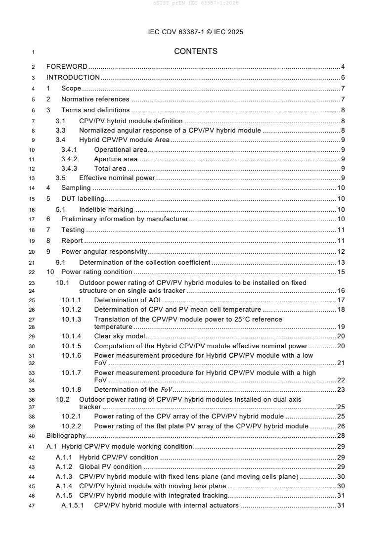
1 CONTENTS
2 FOREWORD . 4
3 INTRODUCTION . 6
4 1 Scope . 7
5 2 Normative references . 7
6 3 Terms and definitions . 8
7 3.1 CPV/PV hybrid module definition . 8
8 3.3 Normalized angular response of a CPV/PV hybrid module . 8
9 3.4 Hybrid CPV/PV module Area . 9
10 3.4.1 Operational area . 9
11 3.4.2 Aperture area . 9
12 3.4.3 Total area . 9
13 3.5 Effective nominal power . 9
14 4 Sampling . 10
15 5 DUT labelling . 10
16 5.1 Indelible marking . 10
17 6 Preliminary information by manufacturer . 10
18 7 Testing . 11
19 8 Report . 11
20 9 Power angular responsivity . 12
21 9.1 Determination of the collection coefficient . 13
22 10 Power rating condition . 15
23 10.1 Outdoor power rating of CPV/PV hybrid modules to be installed on fixed
24 structure or on single axis tracker . 16
25 10.1.1 Determination of AOI . 17
26 10.1.2 Determination of CPV and PV mean cell temperature . 18
27 10.1.3 Translation of the CPV/PV module power to 25°C reference
28 temperature . 19
29 10.1.4 Clear sky model . 20
30 10.1.5 Computation of the Hybrid CPV/PV module effective nominal power . 20
31 10.1.6 Power measurement procedure for Hybrid CPV/PV module with a low
32 FoV . 21
33 10.1.7 Power measurement procedure for Hybrid CPV/PV module with a high
34 FoV . 22
35 10.1.8 Determination of the FoV . 23
36 10.2 Outdoor power rating of CPV/PV hybrid modules installed on dual axis
37 tracker . 25
38 10.2.1 Power rating of the CPV array of the CPV/PV hybrid module . 25
39 10.2.2 Power rating of the flat plate PV array of the CPV/PV hybrid module . 26
40 Bibliography . 28
41 A.1 Hybrid CPV/PV module working condition . 29
42 A.1.1 Hybrid CPV/PV condition . 29
43 A.1.2 Global PV condition . 29
44 A.1.3 CPV/PV hybrid module with fixed lens plane (and moving cells plane) . 30
45 A.1.4 CPV/PV hybrid module with moving lens plane . 30
46 A.1.5 CPV/PV hybrid module with integrated tracking. 31
47 A.1.5.1 CPV/PV hybrid module with internal actuators . 31
oSIST prEN IEC 63387-1:2026
IEC CDV 63387-1 © IEC 2025
48 A.1.5.2 CPV/PV hybrid module with external actuators . 31
49 B.1 Transient test for hybride CPV/PV module with internal solar tracking . Error! Bookmark
50 not defined.
52 Figure 1 - Example of the Hybrid CPV/PV module power variation as a funtion of AOI,
53 compared with the cos(AOI) behaviour (after[1]) . 8
54 Figure 2 - Schematic of a Hybrid CPV/PV module . 9
55 Figure 3 - Schematic of the irradiance terms used in equation (4) for the general case
56 of a hybrid CPV/PV module mounted on a tilted fixed plane. . 13
57 Figure 4 – Example of fitting of equations (7) and (8) for the determination of the
58 collection coefficients : a) εPVθ, 25°, and b) γPVθ, 25°C. . 13
59 Figure 5 – Example of fitting of equations (9), with τ(AOI) =1 for the determination of
60 the collection coefficient φPVext . 14
61 Figure 6 – Example of the determination of the collection coefficient γCPVθ, 25°. . 15
62 Figure 7 - Schematic of the rear module illumination, when the hybrid CPV/PV module
63 adopts bifacial PV solar cells, after [3]. . 15
64 Figure 8. Schematic of sun and tracker angles for the AOI computation . 22
65 Figure 9. Schematic of AOI computation from output coordinates measured by the
66 point sensitive detector. . 23
67 Figure 10. Determination of the FoV from the normalized module power, in case of
68 symmetrical refraction; FoV=16°. . 24
69 Figure 11. Sequence for the determination of the effective nominal power . 24
70 Figure 12. Sequence for the determination of the collection coefficients. . 25
71 Figure 13 - Filtered (red circles) and unfiltered (black circles) front irradiance response
72 (Ifront/GNI) of the PV array of a hybrid CPV/PV module as a function of DNI/GNI.
73 Additionally, the inset shows that the fit to the unfiltered data agrees within 2% with the
74 fit to the filtered data (red line). Reproduced from [3] . 26
75 Figure 14 - Power output of the PV array of a hybrid CPV/PV module translated to STC
76 (blue circles) and SOC (red circles) as a function of BNI. The intercept of the linear fit
77 is fixed to the rated front power output (PPV_front), whereas the slope represents the
78 bifacial power gain (BiFi). Reproduced from [3]. . 27
79 Figure 15- Schematic of the working principle of a hybrid CPV/PV module . 29
80 Figure 16 - Example of a hybrid CPV/PV module power production during the day. The
81 hybrid CPV/PV module has an integrated 2D tracker and it is installed on a tilted roof . 30
82 Figure 17 – Example off a CPV/PV hybrid module with fixed lens plane and a moving
83 cells plane (after[2]) . 30
84 Figure 18 - Example of CPV/PV hybrid modules with moving lenses plane . 31
85 Figure 19 - CPV/PV hybrid module with integrated tracking. . 31
87 Table 1 – Standard test condition (TSC) and standard operating conditions (SOC) for
88 hybrid CPV/PV modules . 16
89 Table 2 – Filtering criteria . 16
oSIST prEN IEC 63387-1:2026
IEC CDV 63387-1 © IEC 2025
92 INTERNATIONAL ELECTROTECHNICAL COMMISSION
93 ____________
95 HYBRID CPV/PV MODULES: GENERAL CHARACTERISTICS AND
96 MEASUREMENT PROCEDURES
98 Part 1: Performance measurement and power rating- irradiance and
99 temperature
101 FOREWORD
102 1) The International Electrotechnical Commission (IEC) is a worldwide organization for standardization comprising
103 all national electrotechnical committees (IEC National Committees). The object of IEC is to promote international
104 co-operation on all questions concerning standardization in the electrical and electronic fields. To this end and
105 in addition to other activities, IEC publishes International Standards, Technical Specifications, Technical Reports,
106 Publicly Available Specifications (PAS) and Guides (hereafter referred to as “IEC Publication(s)”). Their
107 preparation is entrusted to technical committees; any IEC National Committee interested in the subject dealt with
108 may participate in this preparatory work. International, governmental and non-governmental organizations liaising
109 with the IEC also participate in this preparation. IEC collaborates closely with the International Organization for
110 Standardization (ISO) in accordance with conditions determined by agreement between the two organizations.
111 2) The formal decisions or agreements of IEC on technical matters express, as nearly as possible, an international
112 consensus of opinion on the relevant subjects since each technical committee has representation from all
113 interested IEC National Committees.
114 3) IEC Publications have the form of recommendations for international use and are accepted by IEC National
115 Committees in that sense. While all reasonable efforts are made to ensure that the technical content of IEC
116 Publications is accurate, IEC cannot be held responsible for the way in which they are used or for any
117 misinterpretation by any end user.
118 4) In order to promote international uniformity, IEC National Committees undertake to apply IEC Publications
119 transparently to the maximum extent possible in their national and regional publications. Any divergence between
120 any IEC Publication and the corresponding national or regional publication shall be clearly indicated in the latter.
121 5) IEC itself does not provide any attestation of conformity. Independent certification bodies provide conformity
122 assessment services and, in some areas, access to IEC marks of conformity. IEC is not responsible for any
123 services carried out by independent certification bodies.
124 6) All users should ensure that they have the latest edition of this publication.
125 7) No liability shall attach to IEC or its directors, employees, servants or agents including individual experts and
126 members of its technical committees and IEC National Committees for any personal injury, property damage or
127 other damage of any nature whatsoever, whether direct or indirect, or for costs (including legal fees) and
128 expenses arising out of the publication, use of, or reliance upon, this IEC Publication or any other IEC
129 Publications.
130 8) Attention is drawn to the Normative references cited in this publication. Use of the referenced publications is
131 indispensable for the correct application of this publication.
132 9) Attention is drawn to the possibility that some of the elements of this IEC Publication may be the subject of patent
133 rights. IEC shall not be held responsible for identifying any or all such patent rights.
134 IEC 63387-1 has been prepared by subcommittee WG7: CONCENTRATOR MODULS, of IEC
135 technical committee 82 SOLAR PHOTOVOLTAIC ENERGY SYSTEMS. It is an International
136 Standard.
137 The text of this International Standard, Technical Specification is based on the following
138 documents:
Draft Report on voting
XX/XX/FDIS XX/XX/RVD
140 Full information on the voting for its approval can be found in the report on voting indicated in
141 the above table.
142 The language used for the development of this International Standard is English.
oSIST prEN IEC 63387-1:2026
IEC CDV 63387-1 © IEC 2025
143 This document was drafted in accordance with ISO/IEC Directives, Part 2, and developed in
144 accordance with ISO/IEC Directives, Part 1 and ISO/IEC Directives, IEC Supplement, available
145 at www.iec.ch/members_experts/refdocs. The main document types developed by IEC are
146 described in greater detail at www.iec.ch/standardsdev/publications.
147 The committee has decided that the contents of this document will remain unchanged until the
148 stability date indicated on the IEC website under webstore.iec.ch in the data related to the
149 specific document. At this date, the document will be
150 • reconfirmed,
151 • withdrawn,
152 • replaced by a revised edition, or
153 • amended.
oSIST prEN IEC 63387-1:2026
IEC CDV 63387-1 © IEC 2025
155 INTRODUCTION
156 The IEC 61853 and IEC 62670 series establish requirements for evaluating respectively PV and
157 CPV module performances, based on power, energy, and performance ratio (PR). They are
158 applicable to most of PV and CPV technologies, but they do not work well for hybrid CPV/PV
159 modules whose performances can be a discontinuous function of the angle of incidence (AOI),
160 whose geometry can include PV “dead” area besides the module frame and appropriated
161 reference spectra for beam and diffuse components must be defined. The reasons prompting
162 the preparation of this document are therefore related to the need of defining specific terms
163 procedures for the performance measurement of CPV/PV hybrid modules. As some of the hybrid
164 CPV/PV modules consider integrated tracking actuators and internal moving parts, it is foreseen
165 to consider for such modules also specific qualification standard.
oSIST prEN IEC 63387-1:2026
IEC CDV 63387-1 © IEC 2025
168 HYBRID CPV/PV MODULES: GENERAL CHARACTERISTICS AND
169 MEASUREMENT PROCEDURES
171 Part 1: Performance measurement and power rating- irradiance and
172 temperature
175 1 Scope
176 This document specifies the requirements for evaluating CPV/PV hybrid module performance
177 in terms of power rating. Standard conditions for assessing the power produced by the module
178 and the procedures to measure the power as a function of AOI, irradiance, and temperature are
179 defined. A methodology for determining a set of characterization parameter values for the hybrid
180 CPV/PV module (FoV) is also included. In order to compare the performance of different hybrid
181 CPV/PV modules whose output is discontinuous and time-dependent the concept of effective
182 nominal power is introduced. This standard is written to be applicable to CPV/PV hybrid
183 modules which include both solar cells designed to collect concentrated light (CPV cells array)
184 and solar cells designed to collect diffuse or global light (PV cells array), the last ones, with
185 bifacial or monofacial illumination. This document applies for hybrid CPV/PV modules with
186 geometrical concentration ratio >3x to CPV cells. For lower geometrical concentration ratio (≤
187 3x), the IEC 60904-1 and IEC 61853 series apply.
188 2 Normative references
189 The following documents are referred to in the text in such a way that some or all of their content
190 constitutes requirements of this document. For dated references, only the edition cited applies.
191 For undated references, the latest edition of the referenced document (including any
192 amendments) applies.
193 IEC 60904-2, Photovoltaic devices - Part 2: Requirements for photovoltaic reference devices
194 IEC 60904-3, Photovoltaic devices - Part 3: Measurement principles for terrestrial photovoltaic
195 (PV) solar devices with reference spectral irradiance data
196 IEC 60904-5, Photovoltaic devices - Part 5: Determination of the equivalent cell temperature
197 (ECT) of photovoltaic (PV) devices by the open-circuit voltage method
198 IEC TS 61836, Solar photovoltaic energy systems - Terms, definitions and symbols
199 IEC 61853-2, Photovoltaic (PV) module performance testing and energy rating - Part 2: Spectral
200 responsivity, incidence angle and module operating temperature measurements
201 IEC 62670-1, Photovoltaic concentrators (CPV) – Performance testing – Part 1: Standard
202 conditions
203 IEC 62670-3, Photovoltaic concentrators (CPV) - Performance testing - Part 3: Performance
204 measurements and power rating
205 ISO 2859-1, Sampling procedures for inspection by attributes — Part 1: Sampling schemes
206 indexed by acceptance quality limit (AQL) for lot-by-lot inspection
oSIST prEN IEC 63387-1:2026
IEC CDV 63387-1 © IEC 2025
207 3 Terms and definitions
208 For the purposes of this document, the terms and definitions given in IEC 60050, IEC TS 60904-
209 1-2, IEC TS 61836, IEC 62108 and the following apply.
210 ISO and IEC maintain terminological databases for use in standardization at the following
211 addresses:
212 • IEC Electropedia: available at https://www.electropedia.org/
213 • ISO Online browsing platform: available at https://www.iso.org/obp
214 3.1 CPV/PV hybrid module definition
215 CPV/PV hybrid modules include both solar cells designed to collect concentrated light (CPV
216 cells array) and solar cells designed to collect diffuse or global light (PV cells array), with bifacial
217 or monofacial illumination.
218 3.2 Hybrid CPV/PV module field of view (FoV).
219 The Hybrid CPV/PV module FoV is the angles range within which the normalized angular power
220 value of the CPV cells remains within the 50% of its maximum value (see clause 3.3).
222 Note 1 to entry: this definition applies to Hybrid modules with fixed lens plane (and moving cells plane) see Annex
223 1.
225 Note 2 to entry: the FoV is different for the acceptance angle for CPV (as defined in IEC 62670-3). FoV is system
226 related to the optic and the tracking range
229 3.3 Normalized angular response of a CPV/PV hybrid module
The normalized angular response of a CPV/PV hybrid module is the CPV module angular
power normalized to the maximum power condition, computed according to equation (33).
Note 1 to entry: in cases of known asymmetrical refraction properties, the normalized module power shall be
computed along two orthogonal angular directions with respect to the module normal (“X” and “Y” directions).
Note 2 to entry: for CPV/PV hybrid module with integrated tracking, the angular response of a CPV/PV hybrid
module is a strong function of the AOI (see Figure 1 )
Figure 1 - Example of the Hybrid CPV/PV module power variation as a funtion of AOI,
compared with the cos(AOI) behaviour (after[1])
oSIST prEN IEC 63387-1:2026
IEC CDV 63387-1 © IEC 2025
232 3.4 Hybrid CPV/PV module Area
233 In the calculation of the hybrid CPV/PV module efficiency the following area’s definition shall
234 be considered.
235 Note 1 to entry: these definitions are introduced since the hybrid CPV/PV module can present areas which are
236 intentionally not utilized for PV conversion. These areas are found in the case the hybrid CPV/PV module which use
237 2D-3D integrated tracking.
239 3.4.1 Operational area
240 The operational area is the area designed for PV conversion. It concerns the lens area plus any
241 further area covered by solar cells. Referring to Figure 2:
𝑂𝑂𝑂𝑂𝑂𝑂𝑂𝑂𝑂𝑂𝑂𝑂𝑂𝑂𝑂𝑂𝑂𝑂𝑂𝑂𝑂𝑂 𝐴𝐴𝑂𝑂𝑂𝑂𝑂𝑂 =𝐴𝐴𝑂𝑂𝑂𝑂𝑂𝑂(𝐴𝐴) (1)
242 3.4.2 Aperture area
243 The aperture area of the DUT is measured from inside edge to inside edge of the DUT frame
244 (as in 62670-3). Referring to Figure 2:
( )
𝐴𝐴𝑂𝑂𝑂𝑂𝑂𝑂𝑂𝑂𝐴𝐴𝑂𝑂𝑂𝑂 𝐴𝐴𝑂𝑂𝑂𝑂𝑂𝑂 =𝐴𝐴𝑂𝑂𝑂𝑂𝑂𝑂𝐴𝐴 +𝐴𝐴𝑂𝑂𝑂𝑂𝑂𝑂(𝐵𝐵) (2)
245 3.4.3 Total area
246 Total module area is given by the aperture area plus the module frame area. Referring to Figure
247 2:
( ) ( )
𝑇𝑇𝑂𝑂𝑂𝑂𝑂𝑂𝑂𝑂 𝐴𝐴𝑂𝑂𝑂𝑂𝑂𝑂 =𝐴𝐴𝑂𝑂𝑂𝑂𝑂𝑂𝐴𝐴 +𝐴𝐴𝑂𝑂𝑂𝑂𝑂𝑂𝐵𝐵 +𝐴𝐴𝑂𝑂𝑂𝑂𝑂𝑂(𝐶𝐶) (3)
Figure 2 - Schematic of a Hybrid CPV/PV module
250 Note 1 to entry: in some CPV/PV hybrid modules the glass area is covered by silicon or thin film cells. In this case,
251 the hybrid CPV/PV module is said to have an “external” PV array and the area covered by the PV array is part of
252 the operational area.
254 3.5 Effective nominal power
255 The effective nominal power of the CPV/PV hybrid module is the nominal power of a PV module
256 whose performances are continuous function of AOI and that would produce the same yearly
oSIST prEN IEC 63387-1:2026
IEC CDV 63387-1 © IEC 2025
257 energy of the CPV/PV hybrid module under clear sky condition at reference temperature and
258 latitude, respectively of 25°C and of 45°.
260 Note 1 to entry: the concept of effective nominal power shall be applied to hybrid module with integrated solar tracker
261 (see Annex A). The effective nominal power of the CPV/PV hybrid module is computed according to equation (32).
264 4 Sampling
265 For performance qualification testing, three specimens shall be selected at random from a
266 production batch or batches in accordance with the procedure given in ISO 2859-1. For
267 prototype devices which are not from production, sampling shall not apply. This shall be noted
268 in the test report. When the results will be used for name-plate rating, the modules or
269 assemblies, hereafter referred to as device under test (DUT), shall have been manufactured
270 from specified materials and components in accordance with the relevant drawings and process
271 sheets and shall have been subjected to the manufacture’s normal inspection, quality control
272 and production acceptance procedures. The DUT shall be complete in every detail and shall be
273 accompanied by the manufacturer’s handling and final assembly instructions manual regarding
274 the recommended installation of any diodes, frames, brackets, etc.
276 5 DUT labelling
277 5.1 Indelible marking
278 Each module section shall carry the following clear and indelible markings:
279 – Name, monogram, or symbol of manufacturer.
280 – Type or model number.
281 – Serial number.
282 – Polarity of terminals or leads (colour coding is permissible).
283 – Maximum system voltage for which the module or assembly is suitable.
284 – Maximum output power and its tolerance at specified condition (AOI shall be specified
285 if different from zero)
286 – The date, place of manufacture, and cell materials shall be marked, or be traceable from
287 the serial number.
288 If representative samples are used, the same markings as on full-size products shall be included
289 for all tests, and the marking should be capable of surviving all test sequences.
292 6 Preliminary information by manufacturer
293 The necessary values shall be provided by the manufacturer to the test laboratory for the
294 purpose of measurement setup.
296 – Expected maximum power, maximum optical efficiency, Voc, and Isc at STC, (HSTC)
297 concentrator standard operating conditions (HSOC) (see Table.1) and effective nominal
298 power (see equation )).
299 – Field of View (FoV) (see clause 3) or acceptance angle (when the module is installed on
300 a dual axis tracker).
301 – where relevant, the angle range within which the CPV cell array is working. In case of
302 asymmetrical refraction properties, measurements should be taken along two
303 orthogonal angular directions with respect to the module normal
304 – Installation instruction.
305 – Area Ratio = Area(A)/total Area (see Figure 2).
306 – β(t), and γ(t) angles related to the tracker where the hybrid CPV/PV module is intended
307 to be installed (see clause 10.1.1 ))
oSIST prEN IEC 63387-1:2026
IEC CDV 63387-1 © IEC 2025
309 7 Testing
310 The modules shall be subjected to the power and irradiance as a function of AOI, as well of
311 temperature as defined in Section 10. In carrying out the tests, the tester shall observe the
312 manufacturer’s handling, mounting and connection instructions. If the manufacturer’s tracker is
313 not used, the details of the alignment and tracker must be documented in the test report.
316 8 Report
317 Following completion of the procedure, a certified report of the performance tests, with
318 measured power characteristics shall be prepared by the test agency. Each certificate or test
319 report shall include at least the following information.
320 - A title
321 - Name and address of the test laboratory and location (including latitude, longitude and
322 altitude) where the calibration or tests were carried out.
323 - Unique identification of the certification or report and of each page.
324 - Name and address of client, where appropriate.
325 - Description and identification of the item calibrated or tested.
326 - Characterization and condition of the calibration or test item.
327 - Date of receipt of test item and date(s) of calibration or test, where appropriate.
328 - Identification of calibration or test method used.
329 - Reference to sampling procedure, where relevant.
330 - Any deviations from, additions to or exclusions from the calibration or test method, and
331 any other information relevant to a specific calibration or test, such as environmental
332 conditions. Details of the test procedure including the bias (e.g. maximum power or open
333 circuit) maintained between test scans and how the data was filtered to meet the
334 specified criteria.
335 - Measurements, examinations and derived results, including as a minimum table for Isc,
336 Imax, Pmax, Voc, Vmax, Concentrator Nominal Operating Cell Temperature (CNOCT),
337 values of the module thermal coefficients (temperature coefficients of absolute
338 efficiency and power) the effective nominal power and the values for each of the three
339 test modules at all reference power conditions.
340 - A statement of the estimated uncertainty of the calibration or test result, including
341 uncertainty in CNOCT (where relevant).
342 - A statement as to whether the measured CSTC (HSTC), CSOC (HSOC) and nominal powers
343 agree with the manufacturer’s rated power range within the test laboratories
344 measurement uncertainty (if appropriate).
345 - A statement concerning the addition of any blocking diode for the CPV array
346 measurement to avoid damaging the CPV cells in case the current-voltage
347 measurements proceed on the fourth quadrant and whether the IV curve measurements
348 have been corrected for the voltage drop introduced by the blocking diode.
349 - A signature and title, or equivalent identification of the person(s) accepting responsibility
350 for the content of the certificate or report, and the date of issue.
351 - Where relevant, a statement to the effect that the results relate only to the items
352 calibrated or tested.
353 - A statement that the certificate or report shall not be reproduced except in full, without
354 the written approval of the laboratory.
355 - Identification of the tracker used, the tracker alignment sensor, and the documented
356 tracker error.
357 -- Identification of the wind sensor used, the location of the wind sensor, the calibration of
358 the wind sensor.
oSIST prEN IEC 63387-1:2026
IEC CDV 63387-1 © IEC 2025
359 - Identification of the pyrheliometer used and the calibration of the pyrheliometer.
360 - Identification of the pyrometer used and the calibration of the pyrometer.
361 - Identification of the current sensor used.
362 - Identification of the voltage sensor used.
363 - Indication of module alignment method used (as recommended by manufacturer).
364 - indication of the point sensitive detector (used to measure the AOI)
365 - Indication of distance between NIP and module.
366 - A copy of this report shall be kept by the manufacturer for reference purposes.
368 9 Power angular responsivity
369 The most general expression to characterize the power of the hybrid CPV/PV module is the
370 power angular responsivity , which should be preferred to the angular responsivity
371 measurement based on the Isc, in order to take into account to the possible mismatch effects.
373 For front illumination, it holds:
𝑃𝑃 (𝜃𝜃,𝑇𝑇) =𝜀𝜀 (𝜃𝜃,𝑇𝑇)∙𝐷𝐷𝐷𝐷𝐷𝐷𝐷𝐷𝑇𝑇𝐷𝐷(𝜃𝜃) +𝛾𝛾 (𝜃𝜃,𝑇𝑇)∙𝐷𝐷𝑇𝑇𝐷𝐷(𝜃𝜃) +𝜑𝜑 (𝜃𝜃,𝑇𝑇)∙𝐺𝐺𝑇𝑇𝐷𝐷(𝜃𝜃) +𝛾𝛾 (𝜃𝜃,𝑇𝑇)∙𝐷𝐷𝑇𝑇𝐷𝐷(𝜃𝜃)
(4)
𝑓𝑓𝑓𝑓𝑓𝑓𝑓𝑓𝑓𝑓 𝑃𝑃𝑃𝑃 𝑃𝑃𝑃𝑃 𝑃𝑃𝑃𝑃𝑃𝑃𝑃𝑃𝑓𝑓 𝐶𝐶𝑃𝑃𝑃𝑃
𝐷𝐷𝐷𝐷𝐷𝐷𝐷𝐷𝑇𝑇𝐷𝐷(𝜃𝜃) =𝐺𝐺𝑇𝑇𝐷𝐷(𝜃𝜃)−𝐷𝐷𝑇𝑇𝐷𝐷(𝜃𝜃) (5)
( ) ( )
𝐷𝐷𝑇𝑇𝐷𝐷𝜃𝜃 =𝐷𝐷𝐷𝐷𝐷𝐷 0 ∙ 𝑐𝑐𝑂𝑂𝑐𝑐θ (6)
374 Where:
( )
375 𝑃𝑃 𝜃𝜃,𝑇𝑇 is the power angular responsivity generated by the CPV/PV hybrid module,
𝑓𝑓𝑓𝑓𝑓𝑓𝑓𝑓𝑓𝑓
376 expressed in Watts (W), when the AOI is 𝜃𝜃
377 𝜃𝜃 is the Angle of incidence (AOI)
( )
378 𝜀𝜀 𝜃𝜃,𝑇𝑇 is the angular fraction of diffused light absorbed by the PV cells, the unit is in
𝑃𝑃𝑃𝑃
379 square metres (m )
380 𝛾𝛾 (𝜃𝜃,𝑇𝑇) is the angular fraction of direct light scattered or focused by lenses, absorbed
𝑃𝑃𝑃𝑃
381 by the PV cells, expressed in square metres (m ), respectively when θ is inside
382 or outside the FoV
383 𝜑𝜑 (𝜃𝜃,𝑇𝑇) is the angular fraction of global light absorbed by the external PV cells,
𝑃𝑃𝑃𝑃𝑃𝑃𝑃𝑃𝑓𝑓
384 expressed in square metres (m )
385 𝛾𝛾 (𝜃𝜃,𝑇𝑇) is the angular fraction of DNI light absorbed by the CPV cells, expressed in
𝐶𝐶𝑃𝑃𝑃𝑃
386 square metres (m )
( )
387 𝐷𝐷𝑇𝑇𝐷𝐷𝜃𝜃 is the direct tilted irradiance (component of the direct normal irradiance along
388 the module normal expressed in Watts per square metres (W/m ) on a tilted
389 module
390 𝐷𝐷𝐷𝐷𝐷𝐷(0) is the direct normal irradiance
391 𝐺𝐺𝑇𝑇𝐷𝐷(𝜃𝜃) is the global tilted irradiance, expressed in Watts per square metres (W/m ) on
392 a tilted module
393 𝐷𝐷𝐷𝐷𝐷𝐷𝐷𝐷𝑇𝑇𝐷𝐷(𝜃𝜃) is the diffused tilted irradiance, expressed in Watts per square metres (W/m ) on
394 a tilted module
395 𝑇𝑇 is the temperature of the cells
___________
If instead of the power angular responsivity, the power density angular responsivity is considered (which is
expressed in watts per square meters), the coefficients reported in equation (4) are efficiency terms.
oSIST prEN IEC 63387-1:2026
IEC CDV 63387-1 © IEC 2025
398 9.1 Determination of the collection coefficient
399 𝜀𝜀 (𝜃𝜃,𝑇𝑇), 𝛾𝛾 (𝜃𝜃,𝑇𝑇),𝜑𝜑 (𝜃𝜃,𝑇𝑇) and 𝛾𝛾 (𝜃𝜃,𝑇𝑇) are called collection coefficients. The power
𝑃𝑃𝑃𝑃 𝑃𝑃𝑃𝑃 𝑃𝑃𝑃𝑃𝑃𝑃𝑃𝑃𝑓𝑓 𝐶𝐶𝑃𝑃𝑃𝑃
400 angular responsivity is measured according to the procedures reported in clauses 10.1.6 and
401 10.1.7. The values are then translated to 25°C according to clause 10.1.3.
402 For the PV cells (inside the module), it holds:
𝑃𝑃 (𝜃𝜃,𝑇𝑇) 𝐷𝐷𝑇𝑇𝐷𝐷(𝜃𝜃)
𝑓𝑓𝑓𝑓𝑓𝑓𝑓𝑓𝑓𝑓,𝑃𝑃𝑃𝑃
(7)
= �𝛾𝛾 (𝜃𝜃,𝑇𝑇)−𝜀𝜀 (𝜃𝜃,𝑇𝑇)� +𝜀𝜀 (𝜃𝜃,𝑇𝑇)
𝑃𝑃𝑃𝑃 𝑃𝑃𝑃𝑃 𝑃𝑃𝑃𝑃
( ) ( )
𝐺𝐺𝑇𝑇𝐷𝐷𝜃𝜃 𝐺𝐺𝑇𝑇𝐷𝐷𝜃𝜃
𝐷𝐷𝑇𝑇𝐷𝐷(𝜃𝜃)
TILT
407 Figure 3 - Schematic of the irradiance terms used in equation (4) for the general case of
408 a hybrid CPV/PV module mounted on a tilted fixed plane
409 The following equations apply for front illumination, and θ inside the FoV (i.e. for hybrid CPV/PV
410 condition, see annex A)
( )
411 The collection coefficient for diffused radiation, 𝜀𝜀 𝜃𝜃,𝑇𝑇 , can be considered almost constant (as
𝑃𝑃𝑃𝑃
412 it is very weakly dependent on AOI) and it can be computed at normal incidence from the fitting
413 of equation ) by assuming in first approximation 𝛾𝛾 (𝜃𝜃,𝑇𝑇) = 0. Once 𝑃𝑃 is translated to 25°C
𝑃𝑃𝑃𝑃 𝑓𝑓𝑓𝑓𝑓𝑓𝑓𝑓𝑓𝑓,𝑃𝑃𝑃𝑃
414 and given 𝜀𝜀 (𝜃𝜃 = 0°, 25°), the approximated value of 𝛾𝛾 (𝜃𝜃, 25°𝐶𝐶) can then be computed by
𝑃𝑃𝑃𝑃 𝑃𝑃𝑃𝑃
415 rearranging Equation ), and getting a polynomial fitting of equation (8):
𝑃𝑃 (𝜃𝜃, 25°𝐶𝐶) 𝐺𝐺𝑇𝑇𝐷𝐷(𝜃𝜃) (8)
𝑓𝑓𝑓𝑓𝑓𝑓𝑓𝑓𝑓𝑓,𝑃𝑃𝑃𝑃
( ) ( )
𝛾𝛾 𝜃𝜃, 25°𝐶𝐶 = +𝜀𝜀 𝜃𝜃 = 0°, 25°𝐶𝐶 �1− �
𝑃𝑃𝑃𝑃 𝑃𝑃𝑃𝑃
( ) ( )
𝐷𝐷𝑇𝑇𝐷𝐷𝜃𝜃 𝐷𝐷𝑇𝑇𝐷𝐷𝜃𝜃
a) b)
416 Figure 4 – Example of fitting of equations (7) and (8) for the determination of the
( ) ( )
417 collection coefficients : a) 𝜺𝜺 𝜽𝜽,𝟐𝟐𝟐𝟐° , and b) 𝜸𝜸 𝜽𝜽,𝟐𝟐𝟐𝟐°𝑪𝑪
𝑷𝑷𝑷𝑷 𝑷𝑷𝑷𝑷
oSIST prEN IEC 63387-1:2026
IEC CDV 63387-1 © IEC 2025
( )
418 𝜑𝜑 𝜃𝜃,𝑇𝑇 can be computed through a polynomial fitting of equation (9)
𝑃𝑃𝑃𝑃𝑃𝑃𝑃𝑃𝑓𝑓
( )
𝑃𝑃 𝜃𝜃,𝑇𝑇
𝑓𝑓𝑓𝑓𝑓𝑓𝑓𝑓𝑓𝑓,𝑃𝑃𝑃𝑃𝑓𝑓
(9)
𝜑𝜑 (𝜃𝜃,𝑇𝑇) =𝜑𝜑 ·𝜏𝜏(𝜃𝜃) =
𝑃𝑃𝑃𝑃𝑃𝑃𝑃𝑃𝑓𝑓 𝑃𝑃𝑃𝑃𝑃𝑃𝑃𝑃𝑓𝑓
( )
𝐺𝐺𝑇𝑇𝐷𝐷𝜃𝜃
420 where 𝜏𝜏(𝜃𝜃) is transmission coefficient reported in equation 5 of IEC 61853-2, with a =0,18.
r
−𝑐𝑐𝑂𝑂𝑐𝑐𝐴𝐴𝑂𝑂𝐷𝐷
1−𝑂𝑂𝑒𝑒𝑂𝑂� �
𝑂𝑂
𝑓𝑓
𝜏𝜏(𝐴𝐴𝑂𝑂𝐷𝐷) =
(10)
−1
1−𝑂𝑂𝑒𝑒𝑂𝑂� �
𝑂𝑂
𝑓𝑓
( )
421 Once 𝑃𝑃 𝜃𝜃,𝑇𝑇 is translated to 25°C and by considering the measurements performed in a
𝑓𝑓𝑓𝑓𝑓𝑓𝑓𝑓𝑓𝑓,𝑃𝑃𝑃𝑃𝑓𝑓
422 reduced AOI range, 𝜑𝜑 can be computed by the polynomial fitting of equation (9) by
𝑃𝑃𝑃𝑃𝑃𝑃𝑃𝑃𝑓𝑓
423 assuming 𝜏𝜏(𝐴𝐴𝑂𝑂𝐷𝐷) =1 . The value of 𝜑𝜑 (𝜃𝜃,𝑇𝑇) is then simply computed by multiplying 𝜑𝜑
𝑃𝑃𝑃𝑃𝑃𝑃𝑃𝑃𝑓𝑓 𝑃𝑃𝑃𝑃𝑃𝑃𝑃𝑃𝑓𝑓
424 by 𝜏𝜏(𝜃𝜃) , given by equation (10).
425 Figure 5 – Example of fitting of equations (9), with 𝝉𝝉(𝑨𝑨𝑨𝑨𝑨𝑨) =1 for the determination of the
426 collection coefficient 𝝋𝝋
𝑷𝑷𝑷𝑷𝑷𝑷𝑷𝑷𝑷𝑷
427 For the CPV cells, it holds:
( ) ( ) ( )
𝑃𝑃 𝜃𝜃,𝑇𝑇 =𝛾𝛾 𝜃𝜃,𝑇𝑇 ∙𝐷𝐷𝑇𝑇𝐷𝐷𝜃𝜃 (11)
𝑓𝑓𝑓𝑓𝑓𝑓𝑓𝑓𝑓𝑓,𝐶𝐶𝑃𝑃𝑃𝑃 𝐶𝐶𝑃𝑃𝑃𝑃
431 𝛾𝛾 (𝜃𝜃,𝑇𝑇) can be obtained from a (four grade) polynomial fitting of Equation (11). Once
𝐶𝐶𝑃𝑃𝑃𝑃
432 𝑃𝑃 (𝜃𝜃,𝑇𝑇) is translated to 25°C, the polynomial fitting of equation (11) gives 𝛾𝛾 (𝜃𝜃, 25°𝐶𝐶).
𝑓𝑓𝑓𝑓𝑓𝑓𝑓𝑓𝑓𝑓,𝐶𝐶𝑃𝑃𝑃𝑃 𝐶𝐶𝑃𝑃𝑃𝑃
433 For front illumination, and for 𝜃𝜃 >𝐷𝐷𝑂𝑂𝐹𝐹 (i.e for Global PV condition, see annex A), for the inner
( ) ( )
434 PV cells 𝛾𝛾 𝜃𝜃,𝑇𝑇 can be computed by fitting Equation(12), by assuming 𝜀𝜀 𝜃𝜃,𝑇𝑇 equal to the
𝑃𝑃𝑃𝑃 𝑃𝑃𝑃𝑃
435 value determined for θ
𝑃𝑃 (𝜃𝜃,𝑇𝑇) ( )
𝐷𝐷𝑇𝑇𝐷𝐷𝜃𝜃
𝑓𝑓𝑓𝑓𝑓𝑓𝑓𝑓𝑓𝑓,𝑃𝑃𝑃𝑃
= �𝛾𝛾 (𝜃𝜃,𝑇𝑇)−𝜀𝜀 (𝜃𝜃,𝑇𝑇)� +𝜀𝜀 (𝜃𝜃,𝑇𝑇) (12)
𝑃𝑃𝑃𝑃 𝑃𝑃𝑃𝑃 𝑃𝑃𝑃𝑃
𝐺𝐺𝑇𝑇𝐷𝐷(𝜃𝜃) 𝐺𝐺𝑇𝑇𝐷𝐷(𝜃𝜃)
( )
439 𝑃𝑃 𝜃𝜃,𝑇𝑇 can be computed according to equation (9). A reproducible moving plane position has to
𝑓𝑓𝑓𝑓𝑓𝑓𝑓𝑓𝑓𝑓,𝑃𝑃𝑃𝑃𝑓𝑓
440 found also for AOI out of the FoV, (where the inner tracker control could not be operative) to assure
441 reproducible measurement on the inner PV array.
oSIST prEN IEC 63387-1:2026
IEC CDV 63387-1 © IEC 2025
( )
444 Figure 6 shows an example of how to determine the collection coefficient 𝛾𝛾 𝜃𝜃, 25 .
𝐶𝐶𝑃𝑃𝑃𝑃
( )
446 Figure 6 – Example of the determination of the collection coefficient 𝜸𝜸 𝜽𝜽,𝟐𝟐𝟐𝟐°
𝑪𝑪𝑷𝑷𝑷𝑷
448 For back (rear) illumination, only the PV cells convert the solar light:
𝑃𝑃 (𝜃𝜃,𝑇𝑇) =𝜌𝜌 (𝜃𝜃,𝑇𝑇)∙𝐺𝐺𝐷𝐷 (𝜃𝜃,𝜆𝜆) (13)
𝑓𝑓𝑃𝑃𝑟𝑟𝑓𝑓 𝑃𝑃𝑃𝑃 𝑓𝑓𝑃𝑃𝑟𝑟𝑓𝑓
450 Figure 7 - Schematic of the rear module illumination, when the hybrid CPV/PV module
451 adopts bifacial PV solar cells, after [3]
452 10 Power rating condition
453 While hybrid CPV/PV modules convert the global irradiance, power rating conditions have to be
454 differentiated according to the optical losses associated with the AOI and depending on the
455 module electrical layout (number of output terminals). The present power rating procedure
456 applies to hybrid CPV/PV modules where the I-V curves of the CPV cells and of the PV cells
457 can be measured independently. The standard test conditions (STC) and the standard operating
458 conditions (SOC) for hybrid CPV/PV modules with regard to the reference DNI (DNI ) and
ref
459 reference diffuse irradiance (DIFF ) intensity and spectrum, as well as the wind speed (V )
ref wind
460 and cell temperature (Tcell) or ambient temperature (Tamb) are given in Table 1. When hybrid
461 CPV/PV modules are installed on dual axis tracker, the former are identical to those used for
462 flat plate PV modules as given in IEC 60904-3. The latter are identical to the CSOC of CPV
463 modules as given in IEC 62670-1 with the exception that the spectral distribution corresponds
464 to the reference AM1.5 global spectrum scaled to 90% and not to the reference AM1.5 direct
465 spectrum. The same STC are applied when hybrid CPV/PV modules are installed on fixed
466 structures or on single axis trackers, however, in this case, the maximum power is determined
oSIST prEN IEC 63387-1:2026
IEC CDV 63387-1 © IEC 2025
467 instead of the nominal power. The effective nominal power, that keeps into account the optical
468 losses associated with the AOI, is determined as reported in clause 10.1.5.
469 Table 1 – Standard test condition (TSC) and standard operating conditions (SOC) for
470 hybrid CPV/PV modules
Cell Nominal
Direct Wind
Diffuse Irradiance temperat Power/
irradiance speed
Installation Reference
ure Maximum
-2
W·m
Condition -2 -1
power
W·m m·s
°C
AM1.5d AM1.5g-AM1.5d 25 0 Nominal
900 100 Power
HSTC
measured at
AOI=0
On dual
axis tracker
0.9·AM1.5d 0.9·(AM1.5g-AM1.5d) 20 2 Nominal
Power
810 90
HSOC
measured at
AOI=0
AM1.5d AM1.5g-AM1.5d 25 0 Maximum
900 100 Power
HSTC
measured at
On fixed
AOI=0 (*)
structure or
on single
0.9·AM1.5d 0.9·(AM1.5g-AM1.5d) 20 2 Maximum
axis tracker
810 90 Power
HSOC
measured at
AOI=0 (*)
471 (*) or at AOI where the optical efficiency reaches the maximum.
472 10.1 Outdoor power rating of CPV/PV hybrid modules to be installed on fixed
473 structure or on single axis tracker
474 To compare the performance of different hybrid modules whose output is discontinuous and
475 time-dependent the concept of effective nominal power is introduced and computed according
476 to the following procedures. As described in Note 2, in case the CPV/PV hybrid module is
477 installed on a single axis tracker, the module manufacture shall provide the β(t), and γ(t)
478 dependence to be introduced in equation (20) and the effective nominal power will be
479 associated to the behaviour of these tracker related angles. The determination of the effective
480 nominal power foresees the following steps: i) experimental determination of the module power
481 as a function of AOI, while the solar irradiance and ambient condition comply (or are filtered)
482 with the reference condition reported in Table 2, ii) translation of the module power at 25°C, iii)
483 computation of the collection coefficients as a function of AOI @ 25°C, iv) application of a clear
484 sky-model.
485 Table 2 – Filtering criteria
Parameter Data retaining criteria (AOI<𝑭𝑭𝑭𝑭𝑷𝑷) Data retaining criteria (AOI>𝑭𝑭𝑭𝑭𝑷𝑷)
-2 -2 -2 -2
Direct or Global irradiance 600 W·m
ΔDNI <40% ΔGNI <40%
(t-30 min) (t-30 min)
ΔDNI <10% ΔGNI <10%
(t-10 min) (t-10 min)
ΔDNI <1% ΔGNI <1%
(IV-sweep) (IV-sweep)
DNI/GNI>0.6 DNI/GNI>0.2
Direct spectrum 0.97
x-y
Global spectrum 0.97
1-2
Ambient temperature 0°C
amb amb
ΔT <5°C ΔT <5°C
amb(t-30 min) amb(t-30 min)
-1 -1 -1 -1
Wind speed 0.5 m·s
wind(5 min agv) wind(5 min agv)
486 Note: 1) Subscripts in SMR enumerate the component cells in decreasing order of bandgaps. For example, for a
487 InGaP/InGaAs/Ge solar cell, InGaP=1, InGaAs=2, Ge = 3. 2) filtering symmetrically around 20° ambient temperature
488 can be requested by the manufacturer to limit variation in lens performance
...