


prEN IEC 61850-7-4:2026
(Main)Communication networks and systems for power utility automation - Part 7-4: Basic communication structure - Compatible logical node classes and data object classes
General Information
- Abstract
- Status
- Not Published
- Publication Date
- 06-Sep-2027
- Technical Committee
- CLC/TC 57 - Power systems management and associated information exchange
- Current Stage
- 4060 - Enquiry results established and sent to TC, SR, BTTF - Enquiry
- Start Date
- 08-May-2026
- Completion Date
- 08-May-2026

Overview
prEN IEC 61850-7-4:2026 is a core part of the internationally recognized IEC 61850 series for communication networks and systems for power utility automation. This standard, developed by CLC and IEC Technical Committee 57, establishes the basic communication structure through the definition of compatible logical node classes and data object classes. The framework set by this standard is essential for achieving interoperability between intelligent electronic devices (IEDs) in substations, distribution systems, and broader power utility automation environments.
The key practical value of IEC 61850-7-4 lies in its consistent information modeling, supporting efficient, reliable, and standardized data exchange across equipment and systems used in electric power transmission and distribution.
Key Topics
- Logical Node Classes: Definitions and categorization of logical node classes for power utility automation, including abstract, administrative, and system-related logical nodes.
- Data Object Classes: Specification and semantics of data object classes associated with logical nodes for consistent modeling and communication.
- Naming Conventions: Sets rules for normative naming, supporting unambiguous identification and extension, while avoiding incompatible, private extensions.
- Interoperability: Ensures strong, well-defined syntax and semantics for data objects, forming a solid foundation for IED interoperability.
- Device and Function Modeling: Provides models applicable to a wide range of equipment and applications, such as substations, feeders, control centers, distributed generation, and renewable resources.
- Annexes and Namespace Evolution: Addresses compatibility between different revisions, deprecated elements, rules for element presence, statistical calculations, and namespace evolution resulting from the modularization of the standard.
Applications
The scope of IEC 61850-7-4 covers a broad spectrum of power automation networks and systems, supporting:
- Substation and Feeder Equipment: Standardizes communication models for IEDs used in substations and feeders.
- Inter-Substation and Substation-to-Control Center Communication: Facilitates seamless exchange of operational data.
- Power Plant-to-Control Center Communication: Ensures uniform information modeling for integration of power plants into grid management.
- Distributed Generation & DER Integration: Supports renewable resources, such as wind and hydro power plants, with unified data object and node structures.
- Metering and Telecontrol: Enables reliable telemetering and control, crucial for modern smart grid applications.
- Device Configuration and System Description: Underpins tools and engineering processes for system configuration using the Substation Configuration Language (SCL) as specified in IEC 61850-6.
By providing detailed definitions of logical node and data object classes, the standard forms the backbone for IEC 61850-based digital substations and intelligent grids, supporting functions like protection, control, monitoring, and automation.
Related Standards
prEN IEC 61850-7-4:2026 is part of a modular standard series. For a comprehensive automation solution, it should be used in conjunction with the following related standards:
- IEC 61850-7-1: Basic principles and models
- IEC 61850-7-2: Abstract communication service interface (ACSI)
- IEC 61850-7-3: Common data classes
- IEC 61850-6: Substation Configuration Language (SCL)
- IEC 61850-9-2: Sampled values over communication networks
- IEC TS 61850-2: Glossary and terminology
- IEC 61850-7-40, 7-43, 7-44, 7-400, 7-401, 7-440: Domain-specific logical node extensions (e.g., primary equipment, instrument transformers, protection, power quality)
Adopting prEN IEC 61850-7-4:2026 assures future-proof interoperability, streamlined engineering, and robust integration across power utility automation projects worldwide, forming the core data modeling foundation for modern communication in electric power systems.
Relations
- Effective Date
- 23-Sep-2025
- Effective Date
- 23-Sep-2025
Get Certified
Connect with accredited certification bodies for this standard

ANCE
Mexican certification and testing association.

Intertek Slovenia
Intertek testing, inspection, and certification services in Slovenia.

LNE (Laboratoire National de Métrologie et d'Essais)
French national laboratory for metrology and testing.
Sponsored listings
Frequently Asked Questions
prEN IEC 61850-7-4:2026 is a draft published by CLC. Its full title is "Communication networks and systems for power utility automation - Part 7-4: Basic communication structure - Compatible logical node classes and data object classes". This standard covers: Communication networks and systems for power utility automation - Part 7-4: Basic communication structure - Compatible logical node classes and data object classes
Communication networks and systems for power utility automation - Part 7-4: Basic communication structure - Compatible logical node classes and data object classes
prEN IEC 61850-7-4:2026 is classified under the following ICS (International Classification for Standards) categories: 33.200 - Telecontrol. Telemetering. The ICS classification helps identify the subject area and facilitates finding related standards.
prEN IEC 61850-7-4:2026 has the following relationships with other standards: It is inter standard links to EN 61850-7-4:2010, EN 61850-7-4:2010/A1:2020. Understanding these relationships helps ensure you are using the most current and applicable version of the standard.
prEN IEC 61850-7-4:2026 is associated with the following European legislation: Standardization Mandates: M/490. When a standard is cited in the Official Journal of the European Union, products manufactured in conformity with it benefit from a presumption of conformity with the essential requirements of the corresponding EU directive or regulation.
prEN IEC 61850-7-4:2026 is available in PDF format for immediate download after purchase. The document can be added to your cart and obtained through the secure checkout process. Digital delivery ensures instant access to the complete standard document.
Standards Content (Sample)
SLOVENSKI STANDARD
01-april-2026
Komunikacijska omrežja in sistemi za avtomatizacijo porabe električne energije - 7
-4. del: Osnovna komunikacijska struktura - Združljivi logični vozliščni in
podatkovni razredi
Communication networks and systems for power utility automation - Part 7-4: Basic
communication structure - Compatible logical node classes and data object classes
Kommunikationsnetze und -systeme für die Automatisierung in der elektrischen
Energieversorgung - Teil 7-4: Grundlegende Kommunikationsstruktur - Kompatible
Logikknoten- und Datenklassen
Réseaux et systèmes de communication pour l'automatisation des systèmes électriques
- Partie 7-4: Structure de communication de base - Classes de noeuds logiques et
classes d'objets de données compatibles
Ta slovenski standard je istoveten z: prEN IEC 61850-7-4:2026
ICS:
29.240.30 Krmilna oprema za Control equipment for electric
elektroenergetske sisteme power systems
33.200 Daljinsko krmiljenje, daljinske Telecontrol. Telemetering
meritve (telemetrija)
2003-01.Slovenski inštitut za standardizacijo. Razmnoževanje celote ali delov tega standarda ni dovoljeno.
57/2870/CDV
COMMITTEE DRAFT FOR VOTE (CDV)
PROJECT NUMBER:
IEC 61850-7-4 ED3
DATE OF CIRCULATION: CLOSING DATE FOR VOTING:
2026-02-13 2026-05-08
SUPERSEDES DOCUMENTS:
57/2824/RR
IEC TC 57 : POWER SYSTEMS MANAGEMENT AND ASSOCIATED INFORMATION EXCHANGE
SECRETARIAT: SECRETARY:
Germany Mr Heiko Englert
OF INTEREST TO THE FOLLOWING COMMITTEES: HORIZONTAL FUNCTION(S):
ASPECTS CONCERNED:
Digital content,Electricity transmission and distribution
SUBMITTED FOR CENELEC PARALLEL VOTING NOT SUBMITTED FOR CENELEC PARALLEL VOTING
Attention IEC-CENELEC parallel voting
The attention of IEC National Committees, members of
CENELEC, is drawn to the fact that this Committee Draft for Vote
(CDV) is submitted for parallel voting.
The CENELEC members are invited to vote through the
CENELEC online voting system.
This document is still under study and subject to change. It should not be used for reference purposes.
Recipients of this document are invited to submit, with their comments, notification of any relevant patent rights of which t hey are
aware and to provide supporting documentation.
Recipients of this document are invited to submit, with their comments, notification of any relevant “In Some Countries” clau ses to be
included should this proposal proceed. Recipients are reminded that the CDV stage is the final stage for submitting ISC c lauses. (SEE
AC/22/2007 OR NEW GUIDANCE DOC).
TITLE:
Communication networks and systems for power utility automation – Part 7-4: Basic communication structure –
Compatible logical node classes and data object classes – Core
PROPOSED STABILITY DATE: 2027
NOTE FROM TC/SC OFFICERS:
electronic file, to make a copy and to print out the content for the sole purpose of preparing National Committee positions.
You may not copy or "mirror" the file or printed version of the document, o r any part of it, for any other purpose without
permission in writing from IEC.
IEC CDV 61850-7-4 © IEC 2026
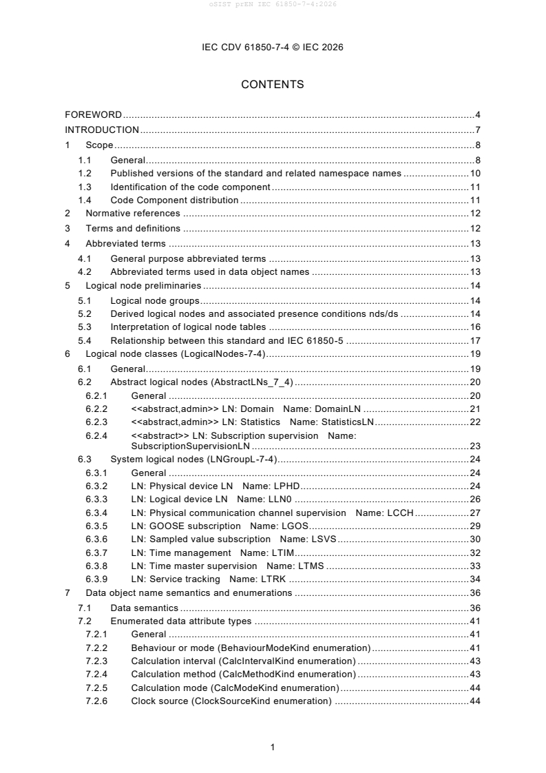
CONTENTS
FOREWORD . 4
INTRODUCTION . 7
1 Scope . 8
1.1 General . 8
1.2 Published versions of the standard and related namespace names . 10
1.3 Identification of the code component . 11
1.4 Code Component distribution . 11
2 Normative references . 12
3 Terms and definitions . 12
4 Abbreviated terms . 13
4.1 General purpose abbreviated terms . 13
4.2 Abbreviated terms used in data object names . 13
5 Logical node preliminaries . 14
5.1 Logical node groups . 14
5.2 Derived logical nodes and associated presence conditions nds/ds . 14
5.3 Interpretation of logical node tables . 16
5.4 Relationship between this standard and IEC 61850-5 . 17
6 Logical node classes (LogicalNodes-7-4) . 19
6.1 General . 19
6.2 Abstract logical nodes (AbstractLNs_7_4) . 20
6.2.1 General . 20
6.2.2 <> LN: Domain Name: DomainLN . 21
6.2.3 <> LN: Statistics Name: StatisticsLN . 22
6.2.4 <> LN: Subscription supervision Name:
SubscriptionSupervisionLN . 23
6.3 System logical nodes (LNGroupL-7-4) . 24
6.3.1 General . 24
6.3.2 LN: Physical device LN Name: LPHD . 24
6.3.3 LN: Logical device LN Name: LLN0 . 26
6.3.4 LN: Physical communication channel supervision Name: LCCH . 27
6.3.5 LN: GOOSE subscription Name: LGOS . 29
6.3.6 LN: Sampled value subscription Name: LSVS . 30
6.3.7 LN: Time management Name: LTIM . 32
6.3.8 LN: Time master supervision Name: LTMS . 33
6.3.9 LN: Service tracking Name: LTRK . 34
7 Data object name semantics and enumerations . 36
7.1 Data semantics . 36
7.2 Enumerated data attribute types . 41
7.2.1 General . 41
7.2.2 Behaviour or mode (BehaviourModeKind enumeration) . 41
7.2.3 Calculation interval (CalcIntervalKind enumeration) . 43
7.2.4 Calculation method (CalcMethodKind enumeration) . 43
7.2.5 Calculation mode (CalcModeKind enumeration) . 44
7.2.6 Clock source (ClockSourceKind enumeration) . 44
IEC CDV 61850-7-4 © IEC 2026
7.2.7 Clock synchronisation (ClockSyncKind enumeration) . 45
7.2.8 Clock synchronisation locking (ClockSyncLockingKind enumeration) . 45
7.2.9 Health (HealthKind enumeration) . 45
7.2.10 Leap Second Consideration (LeapSecondKind enumeration) . 45
7.2.11 Start Week Day (StrWeekDayKind enumeration) . 46
Annex A (normative) Interpretation of mode and behaviour . 47
Annex B (normative) Local / Remote concept . 50
Annex C (informative) Deprecated logical node classes . 52
C.1 General . 52
C.2 LN: Metering statistics Name: MSTA . 52
Annex D (normative) Statistical calculation . 53
D.1 Statistical calculation basis . 53
D.2 Time interval definitions (relating to statistical calculation) . 54
D.2.1 General . 54
D.2.2 Examples . 55
D.3 Calculation start . 56
D.3.1 General . 56
D.3.2 The three possible start conditions available in the model . 56
Annex E (informative) Conditions for element presence . 58
Annex F (normative) Compatibility of the different revisions of the standard . 60
F.1 General . 60
F.2 List of the modifications to consider for backward / forward compatibility . 60
F.3 List of modifications requiring specific treatment . 63
Annex G (normative) Namespace Evolution . 65
G.1 General . 65
G.2 Namespaces dependencies . 65
G.2.1 Basic Namespaces dependencies . 65
G.2.2 Other namespaces dependencies . 66
G.3 Use case scenarios examples for clarifying the namespace evolution . 68
G.3.1 General . 68
G.3.2 Logical Device namespace attribute . 68
G.3.3 Logical Device basic namespace attribute . 68
G.3.4 Logical Node namespace attribute . 68
G.3.5 Evolution of the Namespace in Device implementation . 68
Bibliography . 70
Figure 1 – Overview of this standard and relation of 7-4, 7-4n and 7-4nn series . 9
Figure 2 – Overview of the annexes in 7-4, 7-4n and 7-4nn series . 10
Figure 3 – Class diagram LogicalNodes-7-4::LogicalNodesGroups-7-4 . 19
Figure 4 – Class diagram LogicalNodes-7-4::TopLevelLogicalNodes-7-4 . 20
Figure 5 – Class diagram AbstractLNs_7_4::AbstractLNs-7-4 . 21
Figure 6 – Class diagram LNGroupL-7-4::LNGroupL-7-4 . 24
Figure 7 – State machine of LN LGOS . 29
Figure 8 – State machine of LN LSVS . 31
Figure 9 – Behaviour values as a function of mode . 42
IEC CDV 61850-7-4 © IEC 2026
Figure D.1 – Statistical calculation of a vector . 54
Figure D.2 – Examples of statistical calculations . 56
Figure G.3 - Basic namespaces dependencies . 65
Figure G.4 - IEC 61850 standard series dependencies . 66
Figure G.5 - Other namespaces dependencies . 66
Figure G.6 - Evolution of Namespace in a Device . 69
Table 1 – Tracking information of IEC 61850-7-4:2025A namespace building-up . 6
Table 2 - Published version . 10
Table 3 – Attributes of IEC 61850-7-4:2025A namespace . 11
Table 4 – List of logical node groups . 14
Table 5 – Interpretation of logical node tables . 16
Table 6 – Logical nodes mappings . 17
Table 7 – Data objects of DomainLN . 21
Table 8 – Data objects of StatisticsLN . 22
Table 9 – Data objects of SubscriptionSupervisionLN . 23
Table 10 – Data objects of LPHD . 25
Table 11 – Data objects of LLN0 . 26
Table 12 – Data objects of LCCH . 27
Table 13 – Data objects of LGOS . 29
Table 14 – Data objects of LSVS . 31
Table 15 – Data objects of LTIM . 32
Table 16 – Data objects of LTMS . 33
Table 17 – Data objects of LTRK . 35
Table 18 – Name and description of data objects defined in classes of LogicalNodes -7-
4 package . 36
Table 19 – Literals of BehaviourModeKind . 43
Table 20 – Literals of CalcIntervalKind . 43
Table 21 – Literals of CalcMethodKind . 43
Table 22 – Literals of CalcModeKind . 44
Table 23 – Literals of ClockSourceKind. 44
Table 24 – Literals of ClockSyncKind . 45
Table 25 – Literals of ClockSyncLockingKind . 45
Table 26 – Literals of HealthKind . 45
Table 27 – Literals of LeapSecondKind . 46
Table 28 – Literals of StrWeekDayKind . 46
Table A.1 – Values of mode and behaviour . 48
Table A.2 – Definition of mode and behaviour . 49
Table B.1 – Relationship between Loc/Rem data objects and control authority . 51
Table 2 – Conditions for presence of elements within a context . 58
IEC CDV 61850-7-4 © IEC 2026
INTERNATIONAL ELECTROTECHNICAL COMMISSION
_____________
COMMUNICATION NETWORKS AND
SYSTEMS FOR POWER UTILITY AUTOMATION –
Part 7-4: Basic communication structure –
Compatible logical node classes and data object classes –
Core
FOREWORD
1) The International Electrotechnical Commission (IEC) is a worldwide organization for standardization comprising
all national electrotechnical committees (IEC National Committees). The object of IEC is to promote international
co-operation on all questions concerning standardization in the electrical and electronic fields. To this end and
in addition to other activities, IEC publishes International Standards, Technical Specifications, Technical Reports,
Publicly Available Specifications (PAS) and Guides (hereafter referred to as “IEC Publication(s)”). Their prepa-
ration is entrusted to technical committees; any IEC National Committee interested in the subject dealt with may
participate in this preparatory work. International, governmental and non-governmental organizations liaising with
the IEC also participate in this preparation. IEC collaborates closely with the International Organization for Stand-
ardization (ISO) in accordance with conditions determined by agreement between the two organizations.
2) The formal decisions or agreements of IEC on technical matters express, as nearly as possible, an international
consensus of opinion on the relevant subjects since each technical committee has representation from all inter-
ested IEC National Committees.
3) IEC Publications have the form of recommendations for international use and are accepted by IEC National
Committees in that sense. While all reasonable efforts are made to ensure that the technical content of IEC
Publications is accurate, IEC cannot be held responsible for the way in which they are used or for any misinter-
pretation by any end user.
4) In order to promote international uniformity, IEC National Committees undertake to apply IEC Publications trans-
parently to the maximum extent possible in their national and regional publications. Any divergence between any
IEC Publication and the corresponding national or regional publication shall be clearly indicated in the latter.
5) IEC itself does not provide any attestation of conformity. Independent certification bodies provide conformity
assessment services and, in some areas, access to IEC marks of conformity. IEC is not responsible for any
services carried out by independent certification bodies.
6) All users should ensure that they have the latest edition of this publication.
7) No liability shall attach to IEC or its directors, employees, servants or agents including individual experts and
members of its technical committees and IEC National Committees for any personal injury, property damage or
other damage of any nature whatsoever, whether direct or indirect, or for costs (including legal fees) and ex-
penses arising out of the publication, use of, or reliance upon, this IEC Publication or any other IEC Publications.
8) Attention is drawn to the Normative references cited in this publication. Use of the referenced publications is
indispensable for the correct application of this publication.
9) Attention is drawn to the possibility that some of the elements of this IEC Publication may be the subject of patent
rights. IEC shall not be held responsible for identifying any or all such patent rights.
International Standard IEC 61850-7-4 has been prepared by IEC technical committee 57: Power
systems management and associated information exchange.
IEC CDV 61850-7-4 © IEC 2026
The IEC 61850-7-4 Edition 2.1 is re-organized into the following parts of “Basic communication
structure – Compatible logical node classes and data object classes”, each hereinafter referred
to by the specialized title indicated below:
• IEC 61850-7-4:2025 Edition 3 – Core part (– this document)
• IEC 61850-7-40:2025 Edition 1 – Common part
• IEC 61850-7-43:2025 Edition 1 – Primary equipment
• IEC 61850-7-44:2025 Edition 1 – Instrument transformers
• IEC 61850-7-400:2025 Edition 1 – Substation automation
• IEC 61850-7-401:2025 Edition 1 – Protection
• IEC 61850-7-440:2025 Edition 1 – Power quality and metering
Further in this document these are referenced as 7-4, 7-4n and 7-4nn.
This structure of IEC 61850-7-4 Edition 2.1 has been changed into several parts (7-4, 7-4n and
7-4nn) which allows to update individual parts without requiring a new edition to the core part.
This enables the standard to meet time to market requirements more quickly.
As a consequence, the annexes of former IEC 61850-7-4 Edition 2.1 are now distributed ac-
cording to their purpose. This document includes the following Annexes:
• Annex A (former Annex A) - Interpretation of mode and behaviour
• Annex B (former Annex B) - Local / Remote concept
• Annex C (former Annex C) - Deprecated logical node classes. All deprecated logical node
classes from IEC 61850-7-4 Edition 2.1 are found in this document.
• Annex D (former Annex F) - Statistical calculation
• Annex E (former Annex I) - Conditions for element presence
• Annex F (former Annex J) - Compatibility of the different revisions of the standard.
• Annex G (new Annex) – Namespace Evolution. Describtion of namespace changes intro-
duced by the splitting of IEC 61850-7-4.
IEC 61850-7-4 Edition 2.1 will not be subject to any further improvements with this series being
published.
The new series cancels and replaces IEC 61850-7-4 Edition 2.1 which was last published in
2020 as a consolidated version.
Clauses 4 through 7 and their subclauses (except for 5.1, 5.2, and 5.3) are automatically gen-
erated from the UML model.
The text of this standard is based on the following documents:
FDIS Report on voting
57/XXXX/FDIS 57/XXXX/RVD
This publication has been drafted in accordance with the ISO/IEC Directives, Part 2. This IEC
standard includes Code Components i.e. components that are intended to be directly processed
by a computer.
The purchase of this IEC standard carries a copyright license for the purchaser to sell software
containing Code Components from this standard to end users either directly or via distributors,
subject to IEC software licensing conditions, which can be found at: http://www.iec.ch/CCv1.
IEC CDV 61850-7-4 © IEC 2026
Table 1 shows all tracking information of IEC 61850-7-4:2025A namespace building-up
Table 1 – Tracking information of IEC 61850-7-4:2025A namespace building-up
Attribute Content
Namespace IEC specific information
Version of the UML model used for gener- WG10built18
ating the document (informative)
Date of the UML model used for generating
2025-12-12
the document (informative)
Autogeneration software name and ver- j61850DocBuilder 02.05b based on jCleanCim beta9.4 (derived
sion(informative) from jCleanCim 02-02)
A list of all parts of the IEC 61850 series under the general title Communication networks and
systems for power utility automation, can be found on the IEC website.
The committee has decided that the contents of the base publication and its amendment will
remain unchanged until the stability date indicated on the IEC web site under "http://web-
store.iec.ch" in the data related to the specific publication. At this date, the publication will be
reconfirmed,
withdrawn,
replaced by a revised edition, or
amended.
A bilingual version of this publication may be issued at a later date.
IMPORTANT – The 'colour inside' logo on the cover page of this publication indicates that it
contains colours which are considered to be useful for the correct understanding of its con-
tents. Users should therefore print this document using a colour printer.
IEC CDV 61850-7-4 © IEC 2026
1 INTRODUCTION
2 This part of IEC 61850 is part of a set of standards, the IEC 61850 series. IEC 61850 defines
3 communication networks and systems for power utility automation, and more specifically the
4 communication architecture for subsystems such as substation automation systems. The sum
5 of all subsystems can result also in the description of the communication architecture for the
6 overall power system management. The defined architecture provided in specific parts of
7 IEC 61850-7-n gives both a power utility specific data model and a substation domain specific
8 data model with abstract definitions of data objects classes and services independently from
9 the specific protocol stacks, implementations, and operating systems. The mapping of these
10 abstract classes and services to communication stacks is outside the scope of IEC 61850-7-n
11 and can be found in IEC 61850-8-n and in IEC 61850-9-n.
12 IEC 61850-7-1 gives an overview of the basic communication architecture to be used for all
13 applications in the power system domain. IEC 61850-7-3 defines common attribute types and
14 common data classes related to all applications in the power system domain. The attributes of
15 the common data classes can be accessed using services defined in IEC 61850-7-2. These
16 common data classes are used in this part to define the compatible data object classes.
17 To reach interoperability, all data objects in the data model need a strong definition with regard
18 to syntax and semantics. The semantics of the data objects is mainly provided by names as-
19 signed to common logical nodes defined in this part and the data objects they contain, as de-
20 fined in this basic part, and dedicated logical nodes defined in domain specific parts such as
21 for hydro power control systems. Interoperability is easiest if as many as possible of the data
22 objects are defined as mandatory. Because of different approaches and technical features,
23 some data objects, especially settings, were declared as optional in IEC 61850-7-4:2010 and
24 its following editions. There are also data objects which were declared as conditional, i.e. they
25 will become mandatory under some well-defined conditions. After some experience has been
26 gained with this standard, this decision can be reviewed in the next edition of this part of
27 IEC 61850-7.
28 It is noted that data objects with full semantics are only one of the elements required to achieve
29 interoperability. The standardized access to the data objects is defined in compatible, power
30 utility and domain specific services (see IEC 61850-7-2). Since data objects and services are
31 hosted by devices (IED), a proper device model is also needed. To describe both the device
32 capabilities and the interaction of the devices in the related system, a configuration language
33 is also needed, as defined in IEC 61850-6 by the substation configuration description language
34 (SCL).
35 The compatible logical node name and data object name definitions found in this part and the
36 associated semantics are fixed. The syntax of the type definitions of all data objects classes is
37 governed by abstract definitions provided in IEC 61850-7-2 and IEC 61850-7-3. Not all features
38 of logical nodes are listed in this part; for example, data sets and logs are covered in
39 IEC 61850-7-2.
IEC CDV 61850-7-4 © IEC 2026
42 COMMUNICATION NETWORKS AND
43 SYSTEMS FOR POWER UTILITY AUTOMATION –
45 Part 7-4: Basic communication structure –
46 Compatible logical node classes and data object classes –
47 Core part
48 1 Scope
49 1.1 General
50 This part of IEC 61850 specifies the information model of devices and functions generally re-
51 lated to common use regarding applications in systems for power utility automation. In particu-
52 lar, it specifies the compatible logical node names and data object names for communication
53 between intelligent electronic devices (IED). This includes the relationship between logical
54 nodes and data objects.
55 The logical node names and data object names defined in this document are part of the class
56 model introduced in IEC 61850-7-1 and defined in IEC 61850-7-2. These names are used to
57 build the hierarchical object references applied for communicating with IEDs in systems for
58 power utility automation and, especially, with IEDs in substations and on distribution feeders.
59 The naming conventions of IEC 61850-7-2 are applied in this part.
60 To avoid private, incompatible extensions, this part specifies normative naming rules for multi-
61 ple instances and private, compatible extensions of logical node (LN) classes and data object
62 names. Any definition is based on IEC 61850 or on referenced well identified public documents.
63 This section does not include tutorial material. It provides content that assumes prior knowledge
64 of IEC 61850-5 and IEC 61850-7-1, together with IEC 61850-7-3 and IEC 61850-7-2.
65 This standard and its direct counterparts (7-4, 7-4n and 7-4nn) are applicable to describe device
66 models and functions for:
67 • substation and feeder equipment,
68 • substation-to-substation information exchange,
69 • substation-to-control centre information exchange,
70 • power plant-to-control centre information exchange,
71 • information exchange for distributed generation,
72 • information exchange for distributed energy resources,
73 • information exchange for metering,
74 • information exchanged for hydro power plants, or
75 • information exchange for wind generation plants.
76 Figure 1 provides a general overview of this standard, the groups of logical nodes and the new
77 structure after the split. For convenience, the logical nodes are defined below in alphabetical
78 order within its part.
79 Figure 2 gives an overview of the annexes used in the series of 7-4, 7-4n and 7-4nn.
IEC CDV 61850-7-4 © IEC 2026
82 Figure 1 – Overview of this standard and relation of 7-4, 7-4n and 7-4nn series
IEC CDV 61850-7-4 © IEC 2026
84 Figure 2 – Overview of the annexes in 7-4, 7-4n and 7-4nn series
85 1.2 Published versions of the standard and related namespace names
86 Table 2 provides a reference between all published editions, amendments or corrigenda of this
87 document and the full name of the namespace.
88 Table 2 - Published version
Edition Publication date Webstore Namespace
Edition 1.0 2003-05 IEC 61850-7-4:2003 IEC 61850-7-4:2003
Edition 2.0 2010-03 IEC 61850-7-4:2010 IEC 61850-7-4:2007
Amendment 1 of Edition 2018 IEC 61850-7-4:2010/AMD1:2018 IEC 61850-7-4:2007B
2.0
Edition 2.1 2018 IEC 61850-7-4:2010+AMD1:2018 CSV IEC 61850-7-4:2007B
Edition 2025 20nn-nn IEC 61850-7-4:20nn IEC 61850-7-4:2025A3
IEC CDV 61850-7-4 © IEC 2026
90 1.3 Identification of the code component
92 Table 3 shows all attributes of IEC 61850-7-4:2025A namespace.
93 Table 3 – Attributes of IEC 61850-7-4:2025A namespace
Attribute Content
Namespace nameplate
Namespace Identifier IEC 61850-7-4
Version 2025
Revision A
Release 3
Full Namespace Name IEC 61850-7-4:2025A
Full Code Component Name IEC_61850-7-4.NSD.2025A.Full
Light Code Component Name IEC_61850-7-4.NSD.2025A.Light
Namespace Type basic
Namespace dependencies
dependsOn IEC 61850-7-3:2007B version :2007 revision :B
95 1.4 Code Component distribution
96 Each Code Component is a ZIP package containing the electronic representation of the Code
97 Component itself, with a file describing the content of the package (IECManifest.xml).
98 The life cycle of a code component is not restricted to the life cycle of the related publication.
99 The publication life cycle goes through two stages, Version (corresponding to an edition) and
100 Revision (corresponding to an amendment). A third publication stage (Release) allows publica-
101 tion of Code Component in case of urgent fixes of InterOp Tissues, thus without need to publish
102 an amendment.
103 Consequently, new releases of the Code Component might be released, which supersedes the
104 previous release, and will be distributed through the IEC TC57 web site at:
105 https://www.iec.ch/tc57/supportdocuments
106 The code component associated to this document is a nsd file. It is available as a full version
107 and a light version. The light version is freely accessible on the IEC website for download at
108 https://www.iec.ch/tc57/supportdocuments, but the usage remains under the licensing condi-
109 tions.
110 The latest version/release of the code component will be found by selecting the file for the code
111 component with the highest value for VersionStateInfo, e.g. IEC_61850-6-
112 100.XSD.{VersionStateInfo}.full.zip
113 In case of any differences between the downloadable code component and the IEC pdf pub-
114 lished content, the downloadable code component is the valid one; it might be subject to up-
115 dates. See included history files.
IEC CDV 61850-7-4 © IEC 2026
119 2 Normative references
120 The following documents are referred to in the text in such a way that some or all of their content
121 constitutes requirements of this document. For dated references, only the edition cited applies.
122 For undated references, the latest edition of the referenced document (including any amend-
123 ments) applies.
124 IEC TS 61850-2, Communication networks and systems for power utility automation - Part 2:
125 Glossary
126 IEC 61850-5, Communication networks and systems for power utility automation - Part 5: Com-
127 munication requirements for functions and device models
128 IEC 61850-7-1:2020, Communication networks and systems for power utility automation - Part
129 7-1: Basic communication structure - Principles and models
130 IEC 61850-7-2:2020, Communication networks and systems for power utility automation - Part
131 7-2: Basic information and communication structure - Abstract communication service interface
132 (ACSI)
133 IEC 61850-7-3:2020, Communication networks and systems for power utility automation - Part
134 7-3: Basic communication structure - Common data classes
135 IEC 61850-9-2, Communication networks and systems for power utility automation - Part 9-2:
136 Specific communication service mapping (SCSM) - Sampled values over ISO/IEC 8802-3
137 IEEE C37.2:2022, Electrical Power System Device Function Numbers and Contact Designation
138 3 Terms and definitions
139 For the purposes of this document, the terms and definitions given in IEC 61850-2:2019,
140 IEC 61850-7-2:2020 and IEC 61850-7-4:2020, as well as the following, apply.
141 ISO and IEC maintain terminological databases for use in standardization at the following ad-
142 dresses:
143 • IEC Electropedia: available at http://www.electropedia.org/
144 • ISO Online browsing platform: available at http://www.iso.org/obp
145 3.1 <> logical node class
146 abstract logical node class which is never instantiated, used to group common data objects into
147 a semantically meaningful entity and reuse them in a logical node class through inheritance
148 3.2 <> logical node class
149 abstract logical node class with one special rule for changing the presence condition of some
150 of its data objects when they are inherited in the derived statistics (“ds”) context: in a logical
151 node that does not inherit from statistics logical node (i.e., Group L), the inherited “ds” presence
152 condition is not applicable (‘na’)
153 3.3 deprecated element
154 element still maintained in this edition of the standard, for backwards compatibility purpose, but
155 which is intended to be phased out in the future
156 Note 1 to entry: A deprecated element by definition indicates what should be used instead.
157 3.4 presence condition
158 condition which specifies the occurance rules of data objects of logical node classes in
159 LNinstances of implementations
160 Note 2 to entry: Annex I shows an overview about possibles presence conditions.
IEC CDV 61850-7-4 © IEC 2026
161 3.5 scheduled entity
162 data object of one of the following common data classes APC, ASG, INS, ING SPC, SPG, ENC
163 or ENG where the control output or the value of the setting may be determined by the scheduling
164 system
165 3.6 scheduling system
166 collection containing a schedule controller and the schedules to which the schedule controller
167 refers
168 Note 3 to entry: The scheduling system is associated to a scheduled entity (by reference in the schedule controller)
169 and determines the behaviour of the scheduled entity.
170 4 Abbreviated terms
171 4.1 General purpose abbreviated terms
ds derived statistics
LD logical device
LN logical node
PresCond presence condition
nds not derived statistics
RMS root mean square
172 4.2 Abbreviated terms used in data object names
173 Abbreviated terms are used to build concatenated data object names. For example, ChNum is
174 constructed by using two terms "Ch" which stands for "Channel" and "Num" which stands for
175 "Number". Thus the concatenated name represents a "channel number". The abbreviation terms
176 used in the model specified by this document are visible in the following :
177 • the full code component distributed with this document
178 • the yearly updated and circulated INF - IEC 61850 Roadmap and Schedule
179 • the file accessible on the UCA IUG for download at :
IEC CDV 61850-7-4 © IEC 2026
182 5 Logical node preliminaries
183 5.1 Logical node groups
184 Logical nodes are grouped according to the logical node groups listed in Table 4. The names
185 of logical nodes shall begin with the character representing the group to which the logical node
186 belongs. For modelling per phase (for example switches or instrument transformers), one in-
187 stance per phase shall be created; for modelling protection per zone or level, one instance per
188 zone or level shall be created also.
189 Table 4 – List of logical node groups
Group indicator Logical node groups
A Automatic control
B Reserved
C Supervisory control
D Distributed energy resources
E Thermal power plant ("Enthalpy")
F Functional blocks
G Generic function references
H Hydro power
I Interfacing and archiving
J Reserved
K Mechanical and non-electrical primary equipment
L System logical nodes
M Metering and measurement
N Reserved
O Reserved
P Protection functions
Q Power quality events detection related
R Protection related functions
S Supervision and monitoring
T Instrument transformer and sensors
U Reserved
V Reserved
W Wind power
X Switchgear
Y Power transformer and related functions
Z Further (power system) equipment
191 5.2 Derived logical nodes and associated presence conditions nds/ds
192 IEC 61850-7-1 introduces the concept of derived logical nodes for statistical calculation pur-
193 pose, as explained in Annex D. These principles have however some direct impacts on whether
194 to accept the presence of data objects in selected logical nodes.
195 IEC 61850-7-3 already includes a stereotype to "tag" the CDCs on which "derived" statistical
196 calculation may apply, by using the <> prefix in front of the sections dealing with
197 these CDC which may support this derivation capability (a needed condition), i.e. may be pre-
198 sent in the context of derived LNs instances for statistical purpose.
IEC CDV 61850-7-4 © IEC 2026
199 This part of IEC 61850 goes further by indicating explicitly for each data object, which presence
200 condition applies in the context of derived LN, for statistical purposes.
201 Two contexts are then introduced in the tables presenting the LN contents:
202 • nds is the common context of Non Derived Statistical case
203 • ds is the specific context where the LN instance is derived from another one (Derived Sta-
204 tistical) of same class, to expose the result of one calculation method (expressed in the
205 ClcMth object and all other objects associated to specify the parameters of the method) on
206 some selected objects derived from the original one.
207 Then for each data object the column of the LN table, which title is "PresCond nds/ds", two
208 fields are present:
209 • a first field expressing the presence condition of the corresponding data object in case of
210 nds context – chosen among the presence conditions expressed in Clause 5 of IEC 61850-
211 7-3:2020.
212 • a second field expressing the presence condition of the same object in case of ds context –
213 chosen among the presence conditions expressed in Clause 5 of IEC 61850-7-3:2020.
214 For example, consider the LN class STMP. A first instance of STMP (thereafter STMP1) is
215 expecting to expose:
216 • the Temperature measurement
217 • the Trip information, based on a selected threshold
218 with no specific statistical calculation method indicated. This LN is not derived from any other
219 source of information.
220 The table specifying LN class STMP indicates that CDCs and presence conditions (PresCond
221 nds/ds) are respectively
222 • "MV" with "O/O" for Tmp
223 • "SPS" with "O/F" for Trip
224 • "ENG" with "O/M" for ClcMth
225 • "ORG" with "F/M" for ClcSrc
226 Then in compliance with the standard, this instance of STMP may contain (among other) Tmp,
227 and Trip, and ClcMth may be absent. ClcSrc shall not be present (F – forbidden).
228 Let us now consider the need for getting the average on a sliding time interval of one hour, of
...