


EN 16564:2014
(Main)Machines and plants for mining and tooling of natural stone - Safety - Requirements for bridge type sawing/milling machines, included numerical control (NC/CNC) versions
General Information
- Abstract
This European Standard deals with all significant hazards, hazardous situations and events, as listed in Clause 4, which are relevant to bridge type machines: sawing, sawing and milling, milling, included numerical control (NC/CNC) versions, designed to saw and mill natural stone and engineered/agglomerated stone as defined by EN 14618:2009, when they are used as intended and under conditions of misuse which are reasonably foreseeable by the manufacturer (see Clause 4).
This European Standard specifies the appropriate technical measures to eliminate or reduce risks arising from the significant hazards.
This European Standard deals with the foreseeable lifetime of the machinery including the phases of transport, assembly, dismantling, disabling and scrapping.
This European Standard also applies to machines fitted with the following facilities/devices:
— mechanical, pneumatic, hydraulic or vacuum workpiece clamping;
— automatic tool change;
— loading and unloading conveyor system;
— tilting and/or rotating head axis;
— rotating workpiece support(s);
— tilting workpiece support(s) when loading;
— lathe unit;
— undercut grooving unit;
— axes operating in accordance with an NC work programme.
This European Standard does not apply to:
— machines intended for operation in a potentially explosive atmosphere;
— machines operating in severe environmental conditions (e.g. extreme temperatures, corrosive environment);
— machines intended for outdoor operation;
— machines which are manufactured before the date of its publication as EN.
- Status
- Withdrawn
- Publication Date
- 02-Dec-2014
- Withdrawal Date
- 22-Sep-2026
- Technical Committee
- CEN/TC 151 - Construction equipment and building material machines - Safety
- Current Stage
- 9960 - Withdrawal effective - Withdrawal
- Start Date
- 18-Nov-2020
- Completion Date
- 23-Sep-2026

Relations
- Effective Date
- 08-Jun-2022
- Effective Date
- 25-Aug-2026
- Effective Date
- 25-Aug-2026
- Effective Date
- 09-Feb-2026
- Effective Date
- 09-Feb-2026
- Refers
EN 60825-1:2007 - Safety of laser products - Part 1: Equipment classification and requirements - Effective Date
- 09-Feb-2026
- Effective Date
- 09-Feb-2026
- Effective Date
- 09-Feb-2026
- Effective Date
- 09-Feb-2026
- Effective Date
- 28-Jan-2026
- Effective Date
- 28-Jan-2026
- Effective Date
- 28-Jan-2026
- Effective Date
- 28-Jan-2026
- Effective Date
- 28-Jan-2026
- Effective Date
- 28-Jan-2026
Get Certified
Connect with accredited certification bodies for this standard

DVS-ZERT GmbH
German welding certification society.

Bureau Veritas Chile
Bureau Veritas certification services in Chile.
Bureau Veritas Peru
Bureau Veritas certification services in Peru.
Sponsored listings
Frequently Asked Questions
EN 16564:2014 is a standard published by the European Committee for Standardization (CEN). Its full title is "Machines and plants for mining and tooling of natural stone - Safety - Requirements for bridge type sawing/milling machines, included numerical control (NC/CNC) versions". This standard covers: This European Standard deals with all significant hazards, hazardous situations and events, as listed in Clause 4, which are relevant to bridge type machines: sawing, sawing and milling, milling, included numerical control (NC/CNC) versions, designed to saw and mill natural stone and engineered/agglomerated stone as defined by EN 14618:2009, when they are used as intended and under conditions of misuse which are reasonably foreseeable by the manufacturer (see Clause 4). This European Standard specifies the appropriate technical measures to eliminate or reduce risks arising from the significant hazards. This European Standard deals with the foreseeable lifetime of the machinery including the phases of transport, assembly, dismantling, disabling and scrapping. This European Standard also applies to machines fitted with the following facilities/devices: — mechanical, pneumatic, hydraulic or vacuum workpiece clamping; — automatic tool change; — loading and unloading conveyor system; — tilting and/or rotating head axis; — rotating workpiece support(s); — tilting workpiece support(s) when loading; — lathe unit; — undercut grooving unit; — axes operating in accordance with an NC work programme. This European Standard does not apply to: — machines intended for operation in a potentially explosive atmosphere; — machines operating in severe environmental conditions (e.g. extreme temperatures, corrosive environment); — machines intended for outdoor operation; — machines which are manufactured before the date of its publication as EN.
This European Standard deals with all significant hazards, hazardous situations and events, as listed in Clause 4, which are relevant to bridge type machines: sawing, sawing and milling, milling, included numerical control (NC/CNC) versions, designed to saw and mill natural stone and engineered/agglomerated stone as defined by EN 14618:2009, when they are used as intended and under conditions of misuse which are reasonably foreseeable by the manufacturer (see Clause 4). This European Standard specifies the appropriate technical measures to eliminate or reduce risks arising from the significant hazards. This European Standard deals with the foreseeable lifetime of the machinery including the phases of transport, assembly, dismantling, disabling and scrapping. This European Standard also applies to machines fitted with the following facilities/devices: — mechanical, pneumatic, hydraulic or vacuum workpiece clamping; — automatic tool change; — loading and unloading conveyor system; — tilting and/or rotating head axis; — rotating workpiece support(s); — tilting workpiece support(s) when loading; — lathe unit; — undercut grooving unit; — axes operating in accordance with an NC work programme. This European Standard does not apply to: — machines intended for operation in a potentially explosive atmosphere; — machines operating in severe environmental conditions (e.g. extreme temperatures, corrosive environment); — machines intended for outdoor operation; — machines which are manufactured before the date of its publication as EN.
EN 16564:2014 is classified under the following ICS (International Classification for Standards) categories: 25.080.20 - Boring and milling machines; 25.080.60 - Sawing machines; 73.120 - Equipment for processing of minerals. The ICS classification helps identify the subject area and facilitates finding related standards.
EN 16564:2014 has the following relationships with other standards: It is inter standard links to EN 16564:2020, ISO 7490:1990, ISO 8598:1996, EN 82079-1:2012, EN 60529:1991, EN 60825-1:2007, EN 61496-1:2013, EN 50370-1:2005, EN 61439-1:2011, EN ISO 11145:2008, EN 1037:1995+A1:2008, EN ISO 11200:2014, EN ISO 14119:2013, EN 2286:1989, EN ISO 4414:2010. Understanding these relationships helps ensure you are using the most current and applicable version of the standard.
EN 16564:2014 is associated with the following European legislation: EU Directives/Regulations: 2006/42/EC; Standardization Mandates: M/396. When a standard is cited in the Official Journal of the European Union, products manufactured in conformity with it benefit from a presumption of conformity with the essential requirements of the corresponding EU directive or regulation.
EN 16564:2014 is available in PDF format for immediate download after purchase. The document can be added to your cart and obtained through the secure checkout process. Digital delivery ensures instant access to the complete standard document.
Standards Content (Sample)
2003-01.Slovenski inštitut za standardizacijo. Razmnoževanje celote ali delov tega standarda ni dovoljeno.1&&1&Maschinen und Anlagen zur Gewinnung und Bearbeitung von Naturstein - Sicherheit - Anforderungen an Brücken-Säge-/Fräsmaschinen einschließlich numerischer Steuerungsversionen (NC/CNC)Machines et équipements pour l'exploitation et l'usinage de pierres naturelles - Sécurité - Prescriptions relatives aux machines à scier/fraiseuses de type pont, y compris les versions à commande numérique (NC/CNC)Machines and plants for mining and tooling of natural stone - Safety - Requirements for bridge type sawing/milling machines, included numerical control (NC/CNC) versions73.120Oprema za predelavo rudninEquipment for processing of minerals25.080.60Strojne žageSawing machines25.080.20FrezalnikiBoring and milling machinesICS:Ta slovenski standard je istoveten z:EN 16564:2014SIST EN 16564:2015en,fr,de01-februar-2015SIST EN 16564:2015SLOVENSKI
STANDARD
EUROPEAN STANDARD NORME EUROPÉENNE EUROPÄISCHE NORM
EN 16564
December 2014 ICS 25.080.20; 25.080.60; 73.120 English Version
Machines and plants for mining and tooling of natural stone - Safety - Requirements for bridge type sawing/milling machines, included numerical control (NC/CNC) versions
Machines et équipements pour l'exploitation et l'usinage de pierres naturelles - Sécurité - Prescriptions relatives aux machines à scier/fraiseuses de type pont, y compris les versions à commande numérique (NC/CNC)
Maschinen und Anlagen zur Gewinnung und Bearbeitung von Naturstein - Sicherheit - Anforderungen an Brücken-Säge-/Fräsmaschinen einschließlich numerischer Steuerungsversionen (NC/CNC) This European Standard was approved by CEN on 13 September 2014.
CEN members are bound to comply with the CEN/CENELEC Internal Regulations which stipulate the conditions for giving this European Standard the status of a national standard without any alteration. Up-to-date lists and bibliographical references concerning such national standards may be obtained on application to the CEN-CENELEC Management Centre or to any CEN member.
This European Standard exists in three official versions (English, French, German). A version in any other language made by translation under the responsibility of a CEN member into its own language and notified to the CEN-CENELEC Management Centre has the same status as the official versions.
CEN members are the national standards bodies of Austria, Belgium, Bulgaria, Croatia, Cyprus, Czech Republic, Denmark, Estonia, Finland, Former Yugoslav Republic of Macedonia, France, Germany, Greece, Hungary, Iceland, Ireland, Italy, Latvia, Lithuania, Luxembourg, Malta, Netherlands, Norway, Poland, Portugal, Romania, Slovakia, Slovenia, Spain, Sweden, Switzerland, Turkey and United Kingdom.
EUROPEAN COMMITTEE FOR STANDARDIZATION
COMITÉ EUROPÉEN DE NORMALISATION EUROPÄISCHES KOMITEE FÜR NORMUNG
CEN-CENELEC Management Centre:
Avenue Marnix 17,
B-1000 Brussels © 2014 CEN All rights of exploitation in any form and by any means reserved worldwide for CEN national Members. Ref. No. EN 16564:2014 ESIST EN 16564:2015
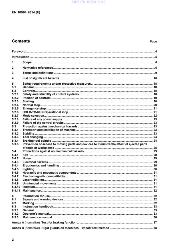
Test for braking function . 37 Annex B (normative)
Rigid guards on machines – Impact test method . 38 SIST EN 16564:2015
Noise Test Code . 41 Annex ZA (informative)
Relationship between this European standard and the essential requirements Of EU Directive 2006/42/EC . 53 Bibliography . 54
EN 166:2001, Personal eye-protection - Specifications EN 349:1993+A1:2008, Safety of machinery - Minimum gaps to avoid crushing of parts of the human body SIST EN 16564:2015
Safeguarding devices are not illustrated Key 1 tool holder head (tilting version) A direction of the tilting movement of the head 2 diamond disk B direction of the tilting movement of the head 3 bridge C direction of the rotating movement of the head 4 carriage W direction of the rotating movement of the workpiece support(s) 5 slide rail X longitudinal movement of the head along the carriage 6 tilting and rotating workpiece support(s) Y transverse movement of the bridge along the slide rail
Z vertical movement of the head Figure 1 — Example of a bridge sawing machine upper tilting head, rotating workpiece support SIST EN 16564:2015
Safeguarding devices are not illustrated Figure 2 — Example of a lathe unit 3.2 bridge sawing and milling machine integrated fed machine designed for sawing, milling and boring workpieces (see Figure 3) by the use of a diamond disk and by a milling tool water cooled installed in the same head unit equipped with a single or double spindle having at least three squared axes (XYZ) Note 1 to entry: This machine can be equipped with the following facilities: a) loading and unloading conveyor system; b) tilting (A/B) and/or rotating (C) head axis; c) rotating workpiece support (s); d) tilting workpiece support(s) when loading; e) lathe unit; f) workpiece vacuum moving system; g) undercut grooving unit; h) mechanical, pneumatic, hydraulic, or vacuum workpieces clamping; i) axes operating in accordance with an NC work programme. SIST EN 16564:2015
Safeguarding devices are not illustrated Key 1 main drive – diamond disk C direction of the rotating movement of the head 2 milling unit X longitudinal movement of the head along the carriage 3 bridge Y transverse movement of the bridge along the slide rail 4 carriage Z vertical movement of the head 5 slide rail
6 tilting and rotating workpiece support (s)
Figure 3 — Example of a bridge sawing and milling machine with double spindle 3.3 numerical control bridge sawing/milling machine integrated fed machines provided with automatic tool change designed for machining of workpieces (see Figure 4) by the use of milling/boring tools and/or diamond disks water cooled with at least three square axes programmable by the user (X, Y, Z) for positioning and/or machining and axes operated in accordance with an NC work programme Note 1 to entry: This machine can be equipped with the following facilities: a) loading and unloading conveyor system; b) tilting (A/B) and/or rotating (C) head axis; c) rotating workpiece support (s); d) tilting workpiece support(s) when loading; e) lathe unit; SIST EN 16564:2015
Safeguarding devices are not illustrated Key 1 tool holder head 7 tool magazine 2 tool 8 PC for numerical control 3 bridge X longitudinal movement of the head along the carriage 4 carriage Y transverse movement of the bridge along the slide rail 5 slide rail Z vertical movement of the head 6 tilting and rotating workpiece support(s)
Figure 4 — Example of a numerical control bridge sawing and milling machine 3.4 manual machining mode of operation manual operation of the machine with the facility for manual or automatic loading/unloading of workpieces 3.5 bumper pressure-sensitive protective device comprising: a) sensor(s) which generate(s) a signal when pressure is applied to part of its outer surface, where: 1) the cross section throughout the pressure-sensitive area may be regular or irregular; 2) the sensor is intended to detect a person or a part of his body (head, arm, leg, etc.) when entering the protected zone; SIST EN 16564:2015
Note 1 to entry: See EN 60204–1:2006, 3.44 and EN ISO 12100:2010, 6.2.12.4. 3.20 monitoring safety function which ensures that a safety measure is initiated if the ability of a component or an element to perform its function is diminished, or if the process conditions are changed in such a way that hazards are generated 3.21 unbraked run-down time time elapsed from the actuation of the stop control, but not the braking device (if fitted) up to spindle standstill 3.22 braked run-down time time elapsed from the actuation of the stop control and the brake device up to spindle standstill 3.23 information of the supplier statements, sales literature, leaflets or other documents where a manufacturer (supplier) declares either the compliance of the characteristics of e.g. a material or product or the conformity of a material or a product to a relevant standard 3.24 peripheral enclosure combination of fixed and moveable guards which enclose the machine danger zone preventing access to it and also form a means of safeguarding against ejected parts which may or may not have a ceiling 3.25 safety function function of the machine whose failure can result in an immediate increase of the risk(s) [SOURCE: EN ISO 12100:2010, 3.30] 3.26 safety-related part of a control system
SRP/CS part of a control system that responds to safety-related input signals and generates safety-related output signals [SOURCE: EN ISO 13849-1:2008, 3.1.1] Note 1 to entry: The combined safety-related parts of a control system start at the point where the safety-related input signals are initiated (including for example, the actuating cam and the roller of the position switch) and end at the output of the power control elements (including, for example, the main contacts of the contactor). Note 2 to entry: If monitoring systems are used for diagnostics, they are also considered as SRP/CS. SIST EN 16564:2015
PL discrete level used to specify the ability of safety-related parts of control systems to perform a safety function under foreseeable conditions [SOURCE: EN ISO 13849-1:2008, 3.1.23, 4.5.1] 3.28 power enabling control device control device that enables providing power to machines actuators Note 1 to entry: E.g. powering auxiliary circuit. 4 List of significant hazards This clause contains all the significant hazards, hazardous situations and events, as indicated in EN ISO 12100:2010, Annex B, identified by risk assessment as significant for this type of machinery and which require action to eliminate or reduce the risk. Table 1 — List of significant hazards Type or group Origin Potential consequences Subclause of this document Mechanical hazards Approach of a moving element to a fixed part Crushing Impact 5.2.7, 5.2.8, 5.2.9, 5.3.5, 5.4.11 Cutting parts Cutting and shearing 5.3.3, 5.3.4, 5.3.5, 5.4.11 Elastic elements Crushing Impact 5.4.11 Gravity Falling objects Impact 5.3.1, 5.3.2 Instability Crushing Impact Being run over 5.3.1, 5.3.2 Kinetic energy Impact Being thrown 5.3.1, 5.3.3, 5.3.4, 5.3.5 Sharp edge Cutting and shearing 5.3.1, 5.3.3, 5.3.4, 5.3.5, 5.4.11 Moving elements Drawing-in Entanglement Being thrown 5.4.11 Rotating elements Cutting, Abrasion, Entanglement, Being thrown 5.3.3, 5.3.4, 5.3.5, 5.4.11 Vacuum Crushing Impact 5.3.5.6 SIST EN 16564:2015
5.4.4 Location of indicators and control devices Discomfort Fatigue Stress Impact Human error 5.4.4 Hazards associated with the environment in which the machine is used
Electromagnetic disturbance Unexpected Start/Stop Break Command failure 5.2.1, 5.2.2, 5.2.3, 5.2.4, 5.2.5, 5.2.6, 5.2.7, 5.2.8, 5.2.9, 5.4.7, 5.4.8 SIST EN 16564:2015
for power enabling: PL = c (see 5.2.3);
for normal stop (braking function excluded): PL = c (see 5.2.4);
for emergency stop (braking function excluded): PL = c (see 5.2.5);
for standstill monitoring: PL = c (see 5.2.6 and 5.2.8);
for tool release: PL = c or two independent systems PL = b (see 5.3.3);
for interlocking with guard locking: PL = c (see 5.2.6, 5.2.7, 5.3.3, 5.3.5.2 and 5.3.5.6);
for hold-to-run control or limited movement control: PL = c or with an enabling device in accordance with EN 60204-1:2006, 9.2.5.2, conforming to PL = c (see 5.2.7.3); SIST EN 16564:2015
for workpiece powered clamping: PL = b (see 5.3.5.6);
for mode selection: PL = c (see 5.2.7);
for trip device: PL = c (see 5.3.5.2, 5.3.5.3 and 5.3.5.4);
for braking function PL = b with additional requirements (see 5.3.4). Verification: By checking the relevant drawings and/or circuit diagrams, calculation and inspection of the machine. 5.2.2 Position of controls 5.2.2.1 General The main electrical control devices that are main interrupter, enabling controls, power enabling, operational/normal stop, emergency stop, mode selection shall be located at the operator's position adjacent to the control display (at the main control panel) at a distance of at least 600 mm and not exceeding 1 800 mm from the floor level. Any safeguarding equipment reset control device shall be located outside the protected zone and shall not be effective if actuated from inside the protected zone (see 5.3.5). The emergency stop device shall be provided at each working station and in particular: a) at the main control panel; b) at the mobile control panel, connected by cable or wireless system (if provided); c) adjacent to all hold-to-run controls; d) adjacent to all limited movement controls; e) at the workpiece loading and unloading area; f) close to or inside the tool magazine, where this is separated from the machining area; g) inside any enclosure fitted with access door if the operator does not have a clear view of the complete machining area from the control position; h) adjacent to all cycle start control devices. Verification: By checking the relevant drawings and/or circuit diagrams, inspection of the machine and functional testing of the machine. 5.2.2.2 Hand-held control sets Additional control devices for cycle starting, operational/normal stopping (if provided) may be duplicated/provided on hand-held control sets with or without cable connection taking account of the requirements of 5.2.5 for emergency stop. No reset function control devices, no power enabling control devices (see 5.2.3) shall be permitted on wireless control sets or control sets with cable connection. When on a wireless control set the connection between the set and the machine is lost, an emergency stop according to 5.2.5 shall be automatically activated. SIST EN 16564:2015
stop the axes movements;
stop spindle rotation; SIST EN 16564:2015
for machines equipped with powered workpiece clamping: maintain workpiece clamping until the machine has come to a complete and safe stop. If the intervention in the machine is allowed only with a change of mode of operation, the features of the control circuit shall be as described in 5.2.7. Verification: By checking the relevant drawings and/or circuit diagrams, inspection of the machine and functional testing of the machine. 5.2.7 Mode selection 5.2.7.1 General Where machines are designed to be operated during setting with the interlocking guards and/or protective devices disabled, a mode selection switch shall be provided to select between the machining and setting modes of operation and the following conditions shall be met: a) the mode selection switch shall be lockable in each position (e.g. by key or password) and shall be located outside the hazards zone, e.g. on the main control panel (see 5.2.2 for location of control devices); b) the control system for mode selection shall be at least PL = c in accordance with the requirements of EN ISO 13849-1:2008; c) the mode selection switch shall not allow more than one mode to be active at any one time; d) the safeguarding requirements given in 5.2.7.2 and 5.2.7.3 shall be effective in their respective mode of operation; e) selecting any of the modes shall not initiate any movement of the machine; f) it shall not be possible to change from automatic to setting mode before the machine has been brought to a complete stop in accordance with 5.2.4. Verification: By checking the relevant drawings and/or circuit diagrams, inspection and functional testing of the machine. 5.2.7.2 Machining mode of operation In machining mode, movement shall only be possible when the interlocking guards (for definition see EN ISO 14119:2013, 3.2 and 3.5) and/or protective devices are in place and functional. The safety-related maximum speed of axes movement shall fulfil the requirements of 5.3.5.3 for speed monitoring and control. Verification: By checking the relevant drawings and/or circuit diagrams and inspection and functional testing of the machine. 5.2.7.3 Machine setting mode of operation In machine setting mode of operation when the moveable guards are open and/or protective devices disabled, any hazardous movement shall only be possible when the following requirements are met: a) tool rotation shall not be possible; b) any single axis (physical or virtual) movement shall be contro
...