


EN 1459:1998+A3:2012
(Main + Amendment)Safety of industrial trucks - Self-propelled variable reach trucks
General Information
- Abstract
1.1 This standard applies to self-propelled seated rider operated variable reach trucks intended to handle loads of all kinds using one of the attachments listed in 3.10 - 3.11 - 3.13 - 3.14 - 3.15 - 3.16 - 3.19 - 3.20. It does not cover the lifting of persons by any attachments, in particular by work platforms. Machines with variable length load suspension elements (chains, ropes etc) from which the load may swing freely in all directions are not covered in this standard. It applies to the handling of series 1 freight containers of length superior or equal to 6 m with the dimensional and securing characteristics as specified in ISO 668 and ISO 3874.
1.2 For the purpose of this standard, self-propelled seated rider operated variable reach trucks (hereinafter referred to as trucks) are counterbalanced lift trucks with one or more articulated arms, telescopic or not, non-slewing, as defined in 4.13.2.2.2 of ISO 5053:1987 used for stacking loads. The load handling means may be mounted directly on the lifting means or on an auxiliary mast fixed at the end of the lifting means. Lifting means shall be non-slewing or have slewing movement not greater than 5° either side of the longitudinal axis of the truck.
1. Vertical Pivoting axis
Figure 1
1.3 Two types of variable reach trucks are covered in this standard:
- industrial trucks for operation on substantially firm smooth, level and prepared surfaces;
- rough terrain trucks for operation on unimproved natural terrain and disturbed terrain or areas.
1.4 Trucks may be equipped with fork arms for normal industrial duties, or attachments for specific applications such as handling freight containers. Trucks may be equipped with stabilisers, axle locking or lateral levelling devices.
1.5 This standard covers all specific hazards which could occur during operation and maintenance of trucks. For hazards occurring during construction, transportation, commissioning, decommissioning and disposal, reference should be
- Status
- Withdrawn
- Publication Date
- 31-Jan-2012
- Withdrawal Date
- 22-Sep-2026
- Technical Committee
- CEN/TC 150 - Industrial trucks - Safety
- Drafting Committee
- CEN/TC 150/WG 2 - Variable reach trucks
- Current Stage
- 9960 - Withdrawal effective - Withdrawal
- Start Date
- 13-Sep-2017
- Completion Date
- 23-Sep-2026
- Directive
- Harmonized Standard2006/42/EC - Directive 2006/42/EC of the European Parliament and of the Council of 17 May 2006 on machinery, and amending Directive 95/16/EC (recast)OJ Ref: C, C 87 OJ Date: 23-Mar-2012

Relations
- Merged From
EN 1459:1998+A2:2010/FprA3 - Safety of industrial trucks - Self-propelled variable reach trucks - Effective Date
- 18-Jan-2023
- Merged From
EN 1459:1998+A2:2010 - Safety of industrial trucks - Self-propelled variable reach trucks - Effective Date
- 12-Nov-2011
- Effective Date
- 08-Jun-2022
- Effective Date
- 08-Jun-2022
- Effective Date
- 25-Aug-2026
- Effective Date
- 25-Aug-2026
- Effective Date
- 25-Aug-2026
- Effective Date
- 25-Aug-2026
- Effective Date
- 25-Aug-2026
- Effective Date
- 25-Aug-2026
- Effective Date
- 25-Aug-2026
- Effective Date
- 25-Aug-2026
- Effective Date
- 25-Aug-2026
- Effective Date
- 25-Aug-2026
- Refers
ISO 6292:1996 - Powered industrial trucks and tractors — Brake performance and component strength - Effective Date
- 09-Feb-2026
Frequently Asked Questions
EN 1459:1998+A3:2012 is a standard published by the European Committee for Standardization (CEN). Its full title is "Safety of industrial trucks - Self-propelled variable reach trucks". This standard covers: 1.1 This standard applies to self-propelled seated rider operated variable reach trucks intended to handle loads of all kinds using one of the attachments listed in 3.10 - 3.11 - 3.13 - 3.14 - 3.15 - 3.16 - 3.19 - 3.20. It does not cover the lifting of persons by any attachments, in particular by work platforms. Machines with variable length load suspension elements (chains, ropes etc) from which the load may swing freely in all directions are not covered in this standard. It applies to the handling of series 1 freight containers of length superior or equal to 6 m with the dimensional and securing characteristics as specified in ISO 668 and ISO 3874. 1.2 For the purpose of this standard, self-propelled seated rider operated variable reach trucks (hereinafter referred to as trucks) are counterbalanced lift trucks with one or more articulated arms, telescopic or not, non-slewing, as defined in 4.13.2.2.2 of ISO 5053:1987 used for stacking loads. The load handling means may be mounted directly on the lifting means or on an auxiliary mast fixed at the end of the lifting means. Lifting means shall be non-slewing or have slewing movement not greater than 5° either side of the longitudinal axis of the truck. 1. Vertical Pivoting axis Figure 1 1.3 Two types of variable reach trucks are covered in this standard: - industrial trucks for operation on substantially firm smooth, level and prepared surfaces; - rough terrain trucks for operation on unimproved natural terrain and disturbed terrain or areas. 1.4 Trucks may be equipped with fork arms for normal industrial duties, or attachments for specific applications such as handling freight containers. Trucks may be equipped with stabilisers, axle locking or lateral levelling devices. 1.5 This standard covers all specific hazards which could occur during operation and maintenance of trucks. For hazards occurring during construction, transportation, commissioning, decommissioning and disposal, reference should be
1.1 This standard applies to self-propelled seated rider operated variable reach trucks intended to handle loads of all kinds using one of the attachments listed in 3.10 - 3.11 - 3.13 - 3.14 - 3.15 - 3.16 - 3.19 - 3.20. It does not cover the lifting of persons by any attachments, in particular by work platforms. Machines with variable length load suspension elements (chains, ropes etc) from which the load may swing freely in all directions are not covered in this standard. It applies to the handling of series 1 freight containers of length superior or equal to 6 m with the dimensional and securing characteristics as specified in ISO 668 and ISO 3874. 1.2 For the purpose of this standard, self-propelled seated rider operated variable reach trucks (hereinafter referred to as trucks) are counterbalanced lift trucks with one or more articulated arms, telescopic or not, non-slewing, as defined in 4.13.2.2.2 of ISO 5053:1987 used for stacking loads. The load handling means may be mounted directly on the lifting means or on an auxiliary mast fixed at the end of the lifting means. Lifting means shall be non-slewing or have slewing movement not greater than 5° either side of the longitudinal axis of the truck. 1. Vertical Pivoting axis Figure 1 1.3 Two types of variable reach trucks are covered in this standard: - industrial trucks for operation on substantially firm smooth, level and prepared surfaces; - rough terrain trucks for operation on unimproved natural terrain and disturbed terrain or areas. 1.4 Trucks may be equipped with fork arms for normal industrial duties, or attachments for specific applications such as handling freight containers. Trucks may be equipped with stabilisers, axle locking or lateral levelling devices. 1.5 This standard covers all specific hazards which could occur during operation and maintenance of trucks. For hazards occurring during construction, transportation, commissioning, decommissioning and disposal, reference should be
EN 1459:1998+A3:2012 is classified under the following ICS (International Classification for Standards) categories: 53.060 - Industrial trucks. The ICS classification helps identify the subject area and facilitates finding related standards.
EN 1459:1998+A3:2012 has the following relationships with other standards: It is inter standard links to EN 1459:1998+A2:2010/FprA3, EN 1459:1998+A2:2010, EN ISO 3691-2:2016, EN 1459-1:2017, ISO 2330:1995, ISO 6055:1997, ISO 9533:1989, ISO 3449:1992, ISO 5053:1987, ISO 3471:1994, ISO 3164:1992, ISO 2867:1994, ISO 3795:1989, ISO 3874:1997, ISO 6292:1996. Understanding these relationships helps ensure you are using the most current and applicable version of the standard.
EN 1459:1998+A3:2012 is associated with the following European legislation: EU Directives/Regulations: 2006/42/EC; Standardization Mandates: M/396. When a standard is cited in the Official Journal of the European Union, products manufactured in conformity with it benefit from a presumption of conformity with the essential requirements of the corresponding EU directive or regulation.
EN 1459:1998+A3:2012 is available in PDF format for immediate download after purchase. The document can be added to your cart and obtained through the secure checkout process. Digital delivery ensures instant access to the complete standard document.
Standards Content (Sample)
2003-01.Slovenski inštitut za standardizacijo. Razmnoževanje celote ali delov tega standarda ni dovoljeno.Sicherheit von Flurförderzeugen - Kraftbetriebene Stapler mit veränderlicher ReichweiteSécurité des chariots de manutention - Chariots automoteurs à portée variableSafety of industrial trucks - Self-propelled variable reach trucks53.060Industrijski tovornjakiIndustrial trucksICS:Ta slovenski standard je istoveten z:EN 1459:1998+A3:2012SIST EN 1459:1999+A3:2012en,fr,de01-julij-2012SIST EN 1459:1999+A3:2012SLOVENSKI
STANDARDSIST EN 1459:1999+A2:20101DGRPHãþD
EUROPEAN STANDARD NORME EUROPÉENNE EUROPÄISCHE NORM
EN 1459:1998+A3
February 2012 ICS 53.060 Supersedes EN 1459:1998+A2:2010 English Version
Safety of industrial trucks - Self-propelled variable reach trucks Sécurité des chariots de manutention - Chariots automoteurs à portée variable
Sicherheit von Flurförderzeugen - Kraftbetriebene Stapler mit veränderlicher Reichweite This European Standard was approved by CEN on 27 November 1998 and includes Corrigendum 1 issued by CEN on 27 September 2006, Amendment 1 approved by CEN on 27 July 2006, Amendment 2 approved by CEN on 19 October 2009 and Amendment 3 approved by CEN on 3 December 2011.
CEN members are bound to comply with the CEN/CENELEC Internal Regulations which stipulate the conditions for giving this European Standard the status of a national standard without any alteration. Up-to-date lists and bibliographical references concerning such national standards may be obtained on application to the CEN-CENELEC Management Centre or to any CEN member.
This European Standard exists in three official versions (English, French, German). A version in any other language made by translation under the responsibility of a CEN member into its own language and notified to the CEN-CENELEC Management Centre has the same status as the official versions.
CEN members are the national standards bodies of Austria, Belgium, Bulgaria, Croatia, Cyprus, Czech Republic, Denmark, Estonia, Finland, France, Germany, Greece, Hungary, Iceland, Ireland, Italy, Latvia, Lithuania, Luxembourg, Malta, Netherlands, Norway, Poland, Portugal, Romania, Slovakia, Slovenia, Spain, Sweden, Switzerland, Turkey and United Kingdom.
EUROPEAN COMMITTEE FOR STANDARDIZATION
COMITÉ EUROPÉEN DE NORMALISATION EUROPÄISCHES KOMITEE FÜR NORMUNG
Management Centre:
Avenue Marnix 17,
B-1000 Brussels © 2012 CEN All rights of exploitation in any form and by any means reserved worldwide for CEN national Members. Ref. No. EN 1459:1998+A3:2012: ESIST EN 1459:1999+A3:2012
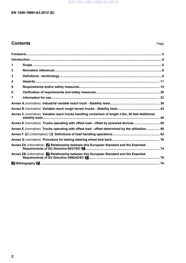
Industrial variable reach truck - Stability tests . 38Annex B (normative)
Variable reach rough terrain trucks - Stability tests . 43Annex C (normative)
Variable reach trucks handling containers of length ≥ 6m, 20 feet-Additional stability tests . 48Annex D (normative)
Trucks operating with offset load - offset by powered devices . 55Annex E (normative)
Trucks operating with offset load - offset determined by the utilisation . 59Annex F ˜(informative)™
Definitions of load handling operations . 63Annex G (normative)
Procedure for testing steering wheel kick back . 70Annex ZA (informative)
####Relationship between this European Standard and the Essential Requirements of EU Directive 98/37/EC$$$$ . 74Annex ZB (informative)
####Relationship between this European Standard and the Essential Requirements of EU Directive 2006/42/EC$$$$ . 75####Bibliography$$$$ . 76 SIST EN 1459:1999+A3:2012
Acknowledging that, at the time of publication, the requirements included in this amendment do not represent the state of the art, a transition period of 12 months is permitted after the date of publication, such that manufacturers can develop their products sufficiently to meet the requirements of this amendment. Attention is drawn to the possibility that some of the elements of this document may be the subject of patent rights. CEN [and/or CENELEC] shall not be held responsible for identifying any or all such patent rights. This European Standard was approved by CEN on 27 November 1998 and includes Corrigendum 1 issued by CEN on 27 September 2006, Amendment 1 approved by CEN on 27 July 2006, Amendment 2 approved by CEN on 19 October 2009 and Amendment 3 approved by CEN on 2011-12-03. This document supersedes %EN 1459:1998+A2:2010&. The start and finish of text introduced or altered by amendment is indicated in the text by tags
!", # $ and %&. The modifications of the related CEN Corrigendum have been implemented at the appropriate places in the text and are indicated by the tags ˜ ™. This European Standard has been prepared under a mandate given to CEN by the European Commission and the European Free Trade Association, and supports essential requirements of EU Directive(s). #For relationship with EU Directive(s), see informative Annexes ZA and ZB, which are integral parts of this document.$ This European Standard is one of a series of European Standards for the safety of Industrial trucks. The complete series is as follows: EN 1726
Safety of Industrial trucks Self propelled trucks up to and including 10,000 kg capacity and tractors with a drawbar pull up to and including 20,000 N. EN 1726-1
Part 1: General requirements EN 1726-2 Part 2: Additional requirements for trucks with elevating operator positions and trucks specifically designed to travel with elevated loads. EN 1551
Safety of Industrial trucks Self propelled trucks over 10,000 kg capacity EN 1459
Safety of Industrial trucks Self propelled variable reach trucks EN 1757
Safety of Industrial trucks Pedestrian propelled trucks SIST EN 1459:1999+A3:2012
Part 1: Stacker trucks EN 1757-2
Part 2: Pallet trucks EN 1757-3
Part 3: Platform trucks EN 1757-4
Part 4: Scissor lift pallet trucks EN 1525
Safety of Industrial trucks Driverless trucks and their systems EN 1175
Safety of Industrial trucks Electrical requirements
EN 1175-1
Part 1: General requirements for battery powered trucks EN 1175-2
Part 2: General requirements for internal combustion engine powered trucks EN 1175-3 Part 3: Specific requirements for the electrical power transmission systems of internal combustion engine powered trucks EN 1526
Safety of Industrial trucks Additional requirements for automated functions on trucks EN 1755
Safety of Industrial trucks Operation in potentially explosive atmospheres: use in flammable gas, vapour mist and dust EN 12053
Safety of Industrial trucks Test methods for measuring noise emissions EN 13564
Safety of Industrial trucks Test methods for measuring visibility from self propelled trucks EN 13059
Safety of Industrial trucks Test methods for measuring vibration EN 12895
Safety of Industrial trucks Electromagnetic compatibility According to the CEN/CENELEC Internal Regulations, the national standards organizations of the following countries are bound to implement this European Standard: Austria, Belgium, Bulgaria, Croatia, Cyprus, Czech Republic, Denmark, Estonia, Finland, France, Germany, Greece, Hungary, Iceland, Ireland, Italy, Latvia, Lithuania, Luxembourg, Malta, Netherlands, Norway, Poland, Portugal, Romania, Slovakia, Slovenia, Spain, Sweden, Switzerland, Turkey and United Kingdom.
1. Vertical Pivoting axis Figure 1
(ISO 13849-2)& ISO 2330:1995, Fork lift trucks — Fork arms — Technical characteristics and testing ISO 2867:1994, Earth moving machinery — Access systems ISO 3164:1992, Earth-moving machinery, roll over and falling object protective structure — Specification for the deflection limiting volume ISO/DIS 3287, Powered industrial trucks — Control systems ISO 3449:1992, Earth moving machinery — Falling object laboratory tests and performance requirements ISO 3471:1994, Earth moving machinery — Roll over protective structures — Test and performances requirements !deleted text" ISO 3795:1989, Road vehicles, and tractors and machinery for agriculture and forestry — Determination of burning behaviour of interior materials ISO 5053:1987, Powered industrial trucks — Terminology ISO 6055:1997, High lift rider trucks — Overhead guards — Specifications and testing ISO 6292:1996, Powered industrial trucks and tractors — Brake performance and component strength ISO/DIS 13284:1997, Fork lift trucks — Fork arm extensions and telescopic fork arms — Technical specifications and strength requirements ISO 9533:1989, Earth moving machinery — Machine mounted forward and reverse audible warning alarm — Sound test method SIST EN 1459:1999+A3:2012
Figure 2 — Parameters for the designation of the rated capacity of the truck 3.2 standard lift height height “H” from the ground to the upper face of the fork blades or to the underside of the load. The standard heights are as follows: H = 3,3 m for trucks with capacities of 10 000 kg or less H = 5,0 m for trucks with capacities of 10 000 kg 3.3 standard load centre distance distance “D” in mm from the centre of gravity “G” of the load measured horizontally to the front face of the fork shanks and vertically to the upper face of the fork blades as specified in table 1. SIST EN 1459:1999+A3:2012
Rated Standard load centre distance D (in mm) load Q (in Kg) 400 500 600 900 1200 1500
<
1 000 X + +
≥
1 000 <
5 000
X +
≥
5 000 ≤ 10 000
X
> 10 000 < 20 000
X X X
≥ 20 000 < 25 000
X X
≥ 25 000
X X NOTE The standard load centre distances D are designated by X.
The load centre distances designated by + are optional.
Trucks may be rated for special applications with load centres related to those applications. 3.4 nominal reach (d) between two vertical parallel planes, one plane is tangent to the front of the outside diameter of the front tyres. The other plane is tangent to the curve described by ‘g’ moving from position ‘H’ to its lowest position. Point ‘g’ is the vertical projection of the centre of gravity ‘G’ onto the plane of the top surface of the fork arm blades 3.5 actual capacity of truck maximum load in kg (depending on lift height “H”, attachment, load centre distance and maximum reach), permitted by the manufacturer, taking into account the stability test results, which the truck is capable of transporting or lifting under specific conditions 3.6 rated capacity of removable attachments maximum load in kg that the attachment is permitted by its manufacturer to handle in normal operation under specified conditions 3.7 axle locking mechanism designed to stop oscillation of the rear axle for improving truck stability during stacking and destacking operations 3.8 stabiliser extendible mechanical supports used to improve stability of a stationary truck 3.9 lateral levelling changing the angular relationship between the chassis and the load axle normally in order to adjust the chassis to horizontal when the truck is standing on a side slope and to ensure the boom operates in a vertical plane 3.10 forks a device including two or more solid fork arms (hook-mounted or shaft mounted) which is fitted on the carriage and usually spread manually 3.11 fork extensions devices fitted over the forks to increase their length SIST EN 1459:1999+A3:2012
4.1 Mechanical hazards
4.1.1 Crushing, shearing or entanglement
4.1.1.1 With truck lifting mechanism 5.6.5 Protection at operator position 4.1.1.2 Within attachment mechanism 5.6.5 Protection on attachment 4.1.1.3 Between truck and obstacles 5.6.1 Operator position : dimensions 4.1.1.4 Between truck and road wheels 5.6.3 Protection from road wheels 4.1.1.5 Within engine compartment 5.4.4 Lockable engine access 4.1.2 Impact by collision
4.1.2.1 When truck is being driven 5.2 Service brakes
5.3.1 Travel controls
5.3.2 Steering controls
5.4.5 Pressure vessel design
5.8.3 Audible warnings
5.5.7.6 Visibility through attachment
5.9 Visibility through operator position
5.10.1.5 Visibility through cab windows
4.1.2.2 When truck is unattended 5.1.2.1 Parking brake 4.1.2.3 Due to mechanical failure 5.2 Brake control system 4.1.3 Impact from falling objects
4.1.3.1 Due to mechanical failure 5.5.1 Lift chains and wire ropes
6 Structural type test
4.1.3.2 Due to unintended load carrier
5.3.3 Load handling control
movement 5.5.2 Lift system leakage
5.5.3.3 Non-return device
4.1.3.3 Due to failure or unintended movement
5.5.4 Fork arms
of fork arms or extensions 5.5.5 Fork extensions
4.1.3.4 Due to unintended movement of load
5.5.5 Fork extensions : retention
handling means 5.5.6 Fork carrier stops
5.5.7.1 Attachment : retention
5.5.7.3 Attachment : fastening device
Hazards Corresponding requirements
4.1.3.5 Due to unstable or insecure loads 5.5.7.2 Load clamping device
5.5.7.7 Spreader twistlock interlock
5.5.8 Load stability
5.8.1 Overhead guard
5.8.2 Protective structure
5.10.1.1/2/3 Cab structure
4.1.3.6 When lifting or transporting the truck 5.10.2 Protection during transport 4.1.4 High pressure hazard
4.1.4.1 Due to hydraulic hose failure 5.5.3.1 Hose burst pressure 4.1.4.2 Due to excessive hydraulic pressure 5.5.3.2 Pressure relief valve
4.1.5 Material ejection from road wheels 5.6.3 Protection from road wheels 4.1.6 Slip, trip, fall
4.1.6.1 During access to operator position 5.6.2 Operator access 4.2 Electrical hazards from contact 5.4.6 Electrical requirements 4.3 Thermal hazards for the operator 5.6.4 Protection from burning
5.10.1.1 Protection from cab heater 4.4 Noise hazards
4.4.1 Hearing loss for the operator 5.10.3.1 Operator noise limitation 4.4.2 Interference with communication 5.10.3.1 Environmental noise limitation 4.5 Vibration hazards 5.6.1 Seat
5.10.3.2 Vibration 4.6 Hazards generated by radiation
Not applicable 4.7 Hazards due to substances
4.7.1 Inhalation of engine exhaust emission 5.4.1 Exhaust port arrangement
4.7.2 Fire or explosion
4.7.2.1 From engine fuel systems 5.4.3 Fuel tanks
5.4.5 LPG requirements 4.7.2.2 From battery electrolyte 5.4.6 Electro technical requirements 4.7.2.3 In hazardous atmospheres 7.1 Instructions for use 4.8 Hazards due to neglect of ergonomic principles
4.8.1 Unhealthy postures 3.21 Definition of normal driving position:
5.6.1 Seat adjustment
5.8.1 Overhead guard : Headroom
5.8.2 Protective structure : Headroom
5.10.1.2 Cab headroom 4.8.2 Inadequate local lighting 5.9.2 Truck lighting 4.8.3 Stress due to operator discomfort 5.4.2 Engine cooling : Air flow
5.10.1.4 Cab : ventilation 4.8.4 Human error
4.8.4.1 During truck operation 5.3 Controls
Annex F Symbols 4.8.4.2 Prior to initial use 6.2 Functional test
7.1 Instruction handbook 4.9 Hazard combinations
Hazards Corresponding requirements
4.10 Hazards due to functional disorders
4.10.1 Hydraulic failure causing load to drop 5.5.3.3 Truck hydraulic system
4.10.2 Control disorder causing uncontrollable movement 5.5.7.4/5 Attachment hydraulic system 4.10.3 Unexpected start-up
4.10.3.1 When truck is unattended 5.1.2.1 Parking brake 4.10.3.2 Due to unauthorised use 5.1.1 Key switch 4.10.3.3 Due to unintended traction 5.1.2.2 Neutral start switch
5.1.2.3/4 Direction and accelerator control
5.1.2.5 Seat or pedal switches 4.10.4 Overturn of truck 5.4.6 Electro technical requirements 4.10.4.1 During truck operation 5.6.6 Safety belt
5.7 Stability tests
5.8.2 Protective structure
5.8.4 Longitudinal stability indicator
5.10.1.6 Cabs : emergency exit 4.10.4.2 When load handling 5.3.4 Other controls
5.5.2 Load lowering speed
7.2.2 Capacity plate 4.10.4.3 When truck is unattended 5.5.2 Hydraulic tilt leakage
4.10.5 Failure of control response 5.5.3.1 Hydraulic burst pressure 4.11 Hazards due to missing or incorrectly positioned safety means
Hazards due to mobility The whole of article 5 4.12 Inadequate lighting of moving/work area 5.9.2 Auxiliary lights 4.13 Hazards due to sudden movement, 5.1 Start up and travel
instability etc. during handling 5.2 Brakes
5.7 Stability - annexes A to E
5.8.1 Overhead guard - ROPS - FOPS
5.10 Environment condition
5.2 ˜6.2 Functionality Structural test™
7.1 Instruction handbook 4.14 Inadequate/in ergonomic design of 5.3 Controls
driving position 5.10 Environmental conditions
4.14.1 Hazards due to dangerous 5.4.5.3 Equipment
environments (contact with moving 5.6.3 Protection from road wheels
parts, exhaust gases etc.) 5.6.4 Protection from burning
5,6.5 Protection of the operator against crushing, 4.14.2 Inadequate visibility from drivers/
shearing and trapping
operators position 5.9 Visibility ˜deleted text™
4.14.3 Inadequate seat/seating (seat index 5.61 Seat
point)
Hazards Corresponding requirements
4.14.4 Inadequate ergonomic/design/ 5.1 Start up and travel
positioning of controls 5.3 Controls
4.14.5 -starting/moving of self propelled 5.1.2 Protection against unintended movement
machinery 5.1.2.5 Transmission isolation
4.14.6 - road traffic of self propelled
Not covered in this standard
machinery
4.14.7 - movement of pedestrian controlled
Not applicable
machinery
4.15 Mechanical hazards
4.15.1 Hazards to exposed persons due to 5.1 Start up and travel
uncontrolled movement
4.15.2 Hazards due to break-up and/or
5.5.3.1 Hydraulic circuit
ejection of parts 5.5.3.3 Failure of energy supply or hydraulic circuit
4.15.3 Hazards due to rolling over (deflection limiting volume; DLV) 5.8.2 Protection against falling objects and overturning
4.15.4 Hazards due to falling objects (DLV) 5.5.7 Load handling attachment
5.8.1 Overhead guard
5.10.1 Operators cab
5.10.2 Protection during transporting, loading and
unloading
7.1 Instruction handbook
4.15.5 Inadequate means of access 5.6.2 Operator access
4.15.6 Hazards caused due to towing,
7.1 Instruction handbook
coupling, connecting, transmission etc.
4.15.7 Hazards due to batteries, fire,
5.1.2.4 Battery powered trucks
emissions etc. 5.4.1/5.4.2Exhaust and cooling systems
5.4.3 Fuel tanks
5.4.5.1 Containers
5.4.5.2 LPG piping
7.1 Instruction handbook Hazards due to lifting Whole clause 5 4.16.1 Lack of stability 5.7 Stability
7.1 Instruction handbook
Annexes A to E 4.16.2 Derailment of machinery
4.16.3 Loss of mechanical strength of
5.5.1.1 Chains
machinery and lifting accessories 5.5.1.2 Ropes
5.5.2 Hydraulic lifting system
6.1.1 Static loading
Hazards Corresponding requirements
4.16.4 Hazards caused by uncontrolled 5.1 Start up and travel
movement 5.2 Brakes
5.3 Controls
5.5.2.1 Load handling
5.5.2.2 Max load lowering speed
5.5.2.3 Limitation of stroke
5.5.3.2 Pressure relief valve
5.5.7 Load handling attachment 4.17 Inadequate view of trajectories of the 5.9 Visibility
moving parts
Annex G 4.18 Hazards caused by lighting
Not applicable 4.19 Hazards due to loading/unloading 5.5.1.1 Chains
5.5.1.2 Ropes
5.5.2 Hydraulic lifting systems
5.5.3.2 Pressure relief valves
5.5.3.3 Failure of energy supply
5.5.7 Load handling attachment
5.8.4 Longitudinal stability indicator
5.8.5 Loading control
6.1.1 Proof testing
7.1 Instruction handbook
5 Requirements and/or safety measures % 5.1 Starting/moving 5.1.1 Unauthorised starting All trucks shall be designed in a way that they cannot be started without a key, a code, a magnetic card or other equivalent device. 5.1.2 Unintended movement Trucks shall be fitted with a device which prevents the engine being started whilst the drive-system is engaged. When the drive system direction control is in neutral, provisions shall be made to locate and maintain it in its neutral position. 5.1.3 Parking brake A parking brake shall be provided complying with 5.2.1 5.1.4 Uncontrolled motion On level ground the truck shall not move from rest until the drive system has been engaged SIST EN 1459:1999+A3:2012
Application of the parking brake shall apply neutral travel control. NOTE "Application of the parking brake shall apply neutral travel control” does not apply to trucks with hydro-static transmission because this transmission system achieves the same objective. 5.1.7 Non-activation of the parking brake A warning shall be activated when the operator is not at the normal operator’s positioonn and the parking brake has not been applied.&
5.2 Brakes 5.2.1 Service and parking brakes shall comply with ISO 6292. 5.2.2 For trucks with capacities greater than 50 000 kg, brake shall also comply with ISO/DIS 6292. 5.2.3 Electromechanical brakes shall be applied mechanically and released electrically, they shall meet the requirements of 5.6 of EN 1175-1:1998. Failure of the power supply for automatically acting brakes shall not result in loss of braking. 5.3 Controls Controls shall, where practicable, be consistent with the truck motions being operated and shall be confined within the plan view outline of the truck. 5.3.1 Travel and braking controls 5.3.1.1 Pedal operated travel and braking controls These shall be in accordance with EN 281:1988. 5.3.1.2 Differential locking pedal If the truck is fitted with a differential lock which is pedal operated, depression of the pedal shall lock the differential. 5.3.1.3 Hand operated direction control lever The movement of a direction control lever shall correspond to the required direction of travel. SIST EN 1459:1999+A3:2012
If other control methods are used, they shall follow the same logic. 5.3.5 Marking Controls shall be legibly and indelibly marked with graphic symbols in accordance with ISO/DIS 3287 (see annex F). # 5.3.6 Multiple operating positions If additional operating positions are fitted, the use of the controls of one operating position shall preclude the use of the controls of the other operating positions at the same time, except the emergency disconnect switch, which shall be operable from all positions.$ 5.4 Power systems and accessories 5.4.1 Exhaust system The exhaust system shall be so designed that the health of the operator is not impaired by temperature rises or exhaust gases. In particular, the exhaust pipe shall have its outlet so arranged as to cause the minimum discomfort to personnel. 5.4.2 Cooling system The air flow through cooling system shall be arranged in such a manner that the health of the operator is not impaired. 5.4.3 Fuel tanks 5.4.3.1 If a fuel tank is within or contiguous to the engine compartment and if the temperature could cause ignition of fuel, the tank and/or filling arrangements shall be isolated from the electrical and exhaust systems by suitable protection such as separate enclosure or baffles. The tank location and facilities for filling shall be such that spillage or leakage will drain to the ground and not into the engine or operator’s compartment or onto electrical or exhaust system parts. 5.4.3.2 Fuel spillage shall not be possible under normal operating conditions. SIST EN 1459:1999+A3:2012
The gas shall be led away safely. See also 5.4.5.3 d). 2) A fixed maximum-level-indicating device. Where containers are fitted inside compartment of vehicles the discharge side of any maximum-level-indicator which relies on bleeding gas to atmosphere shall terminate at a readily visible position on the outside of the vehicle: Maximum-level-indicating devices which rely on bleeding to atmosphere shall be designed so that the bleed hole is not larger than 1,5 mm in diameter and also that the parts of the device cannot be completely withdrawn in normal gauging operations. SIST EN 1459:1999+A3:2012
If a liquid-level-gauge is fitted, it shall not vent to atmosphere. h) If containers are installed in a compartment, this compartment shall have permanent openings at the very bottom. The total surface area of these ventilation openings shall be at least 200 cm2 allowing adequate ventilation to the outside atmosphere and without risk for the operator. i) When containers are removable, their fastenings shall permit easy handling and checking of the installation after the exchange of containers. j) Removable containers which incorporate a safety pressure relief valve shall be so positioned on the truck that the safety pressure relief valve opening is always in communication with the vapour space at the top of the container. This may be accomplished by an indexing pin which positions the container when it is properly installed. k) If a spare or additional container is carried on the truck shall be secured in accordance with the 2nd and 3rd paragraphs of 5.4.5.1. l) Containers shall be positioned in such a way that they are not exposed to the damaging effects of heat, particularly heat from the engine and the exhaust system. It shall be possible to fit a heat-shield which shall not inhibit ventilation under any circumstances. m) Containers shall be fitted on the truck in such a way that they are not exposed to abrasion or shock nor to corrosive action of the products handled by the truck. 5.4.5.2 LPG piping a) Connecting piping and all associated parts shall be easily accessible, protected against damage and wear, and flexible enough to withstand vibration and deformation in service. 1) Piping shall be so arranged that damage or leaks are easily detectable. 2) Piping shall be installed in such a way that it cannot be damaged by the hot parts of the engine. Fully rigid pipes shall not be used for connecting the container to equipment on the engine. 3) High pressure flexible hoses (above 1 bar) shall be supported at least every 500 mm. Rigid pipes shall be supported at least every 600 mm. b) Hoses, pipes and all connections operating at pressures above one bar shall be suitable for a working pressure of 25 bar and shall withstand without bursting a test pressure of 75 bar. c) Hoses, pipes and all connections below one bar shall withstand without bursting a test pressure of five times the maximum pressure likely to be encountered in service. d) Containers and their piping shall be installed in such a way that there are no projections outside the overall contour of the truck. Container connections shall be protected by a rigid guard. e) Excessive pressure shall be avoided in any section of pipe-work containing LPG between two shut-off valves which may be closed; a pressure-relief valve or other suitable means may be used if necessary.
...