


prEN 843-9
(Main)Advanced technical ceramics - Mechanical properties of monolithic ceramics at room temperature - Part 9: Test method for the determination of edge-chip resistance
General Information
- Abstract
This document specifies two test methods for the determination of the resistance of the edges of brittle ceramic materials to be damaged by chipping.
This document is applicable to homogeneous monolithic ceramics with flat surfaces and straight sharp or chamfered edges.
- Status
- Not Published
- Publication Date
- 26-Sep-2027
- Technical Committee
- CEN/TC 184 - Advanced technical ceramics
- Drafting Committee
- CEN/TC 184/WG 3 - Monolithic ceramics
- Current Stage
- 4060 - Closure of enquiry - Enquiry
- Start Date
- 20-Aug-2026
- Due Date
- 03-Aug-2026
- Completion Date
- 20-Aug-2026

Overview
prEN 843-9: Advanced Technical Ceramics - Mechanical Properties of Monolithic Ceramics at Room Temperature - Part 9: Test Method for the Determination of Edge-Chip Resistance is a draft European Standard developed by CEN/TC 184. This standard specifies two practical laboratory test methods for assessing the resistance of homogeneous, monolithic ceramics to edge chipping. These tests are particularly crucial for brittle ceramics with flat surfaces and sharp or chamfered straight edges, and provide quantifiable measures of edge-chip resistance.
The standard updates and supersedes CEN/TS 843-9:2010, with significant editorial and technical revisions, including updated terminology and reference documents. It is intended for use by manufacturers, laboratories, and quality assurance professionals working with advanced ceramic materials.
Key Topics
Edge-Chip Resistance Testing:
The standard describes two complementary methods for determining the susceptibility of ceramic edges to damage:- Method A: Direct Force Application
An indenter applies a steadily increasing load near the edge of the material until chipping occurs, recording the peak force. - Method B: Sliding Force Application
A constant force is applied via a sliding indenter which is moved towards the edge until a chip forms, measuring the distance at which the chip occurs.
- Method A: Direct Force Application
Test Apparatus and Preparation:
- Mechanical testing machines or scratch testers with appropriate force calibration and displacement control.
- Specific sample holding fixtures to ensure correct alignment and positioning for repeatable results.
- Well-prepared ceramic samples with flat surfaces and carefully finished edges (either sharp or chamfered).
- Use of diamond indenters (Rockwell, Vickers, or Knoop geometry) for reliable fracture initiation.
Data Analysis:
- The standard defines the calculation of edge-chip resistance as the applied force divided by the effective distance (for both methods).
- Averaging and standard deviation methods are outlined for comprehensive result analysis.
Reporting Requirements:
- Detailed documentation of all test parameters, materials, and results is mandated, following EN ISO/IEC 17025, ensuring confidence and traceability in measurement in line with international standards.
Applications
Quality Assurance for Advanced Ceramics:
Assessing edge-chip resistance provides essential data on the mechanical reliability of advanced ceramics, widely used in high-performance applications such as electronics, aerospace, automotive, and industrial cutting tools.Material Selection and Design:
Enables comparative evaluation of different ceramic compositions, microstructures, and edge preparations to optimize product performance and durability.Manufacturing Process Validation:
Supports process optimization by evaluating the impact of machining, edge finishing, and chamfering on edge strength and overall component integrity.Failure Analysis and R&D:
Facilitates root cause analysis of component failure due to edge chipping and guides research and development to improve material formulations and surface treatments.
Related Standards
EN 843 Series:
prEN 843-9 is part of the EN 843 series, covering various mechanical properties of monolithic ceramics at room temperature.EN ISO 7500-1
Metallic materials - Calibration and verification of static uniaxial testing machines.EN ISO/IEC 17025
General requirements for competence of testing and calibration laboratories.EN ISO 14705 and EN ISO 20502
Related to hardness testing and scratch testing for ceramic materials.EN 623-4
Determination of surface roughness for monolithic ceramics.
By following prEN 843-9, stakeholders can ensure advanced ceramic components meet stringent durability and reliability standards, leading to safer, higher performance, and longer-lasting products in critical applications. This standard is essential for any industry or laboratory focused on advanced technical ceramics and their mechanical evaluation.
Relations
- Effective Date
- 18-Jun-2025
Frequently Asked Questions
prEN 843-9 is a draft published by the European Committee for Standardization (CEN). Its full title is "Advanced technical ceramics - Mechanical properties of monolithic ceramics at room temperature - Part 9: Test method for the determination of edge-chip resistance". This standard covers: This document specifies two test methods for the determination of the resistance of the edges of brittle ceramic materials to be damaged by chipping. This document is applicable to homogeneous monolithic ceramics with flat surfaces and straight sharp or chamfered edges.
This document specifies two test methods for the determination of the resistance of the edges of brittle ceramic materials to be damaged by chipping. This document is applicable to homogeneous monolithic ceramics with flat surfaces and straight sharp or chamfered edges.
prEN 843-9 is classified under the following ICS (International Classification for Standards) categories: 81.060.30 - Advanced ceramics. The ICS classification helps identify the subject area and facilitates finding related standards.
prEN 843-9 has the following relationships with other standards: It is inter standard links to CEN/TS 843-9:2010. Understanding these relationships helps ensure you are using the most current and applicable version of the standard.
prEN 843-9 is available in PDF format for immediate download after purchase. The document can be added to your cart and obtained through the secure checkout process. Digital delivery ensures instant access to the complete standard document.
Standards Content (Sample)
SLOVENSKI STANDARD
01-julij-2026
Sodobna tehnična keramika - Mehanske lastnosti monolitske keramike pri sobni
temperaturi - 9. del: Preskusna metoda za ugotavljanje odpornosti proti krušenju
robov
Advanced technical ceramics - Mechanical properties of monolithic ceramics at room
temperature - Part 9: Test method for the determination of edge-chip resistance
Hochleistungskeramik - Mechanische Eigenschaften monolithischer Keramik bei
Raumtemperatur - Teil 9: Prüfverfahren zur Bestimmung der Kantenbeständigkeit gegen
Abplatzung
Céramiques techniques avancées - Propriétés mécaniques des céramiques
monolithiques à température ambiante - Partie 9 : Méthode d'essai pour la détermination
de la résistance à l'écaillage des bords
Ta slovenski standard je istoveten z: prEN 843-9
ICS:
81.060.30 Sodobna keramika Advanced ceramics
2003-01.Slovenski inštitut za standardizacijo. Razmnoževanje celote ali delov tega standarda ni dovoljeno.
DRAFT
EUROPEAN STANDARD
NORME EUROPÉENNE
EUROPÄISCHE NORM
May 2026
ICS 81.060.30 Will supersede CEN/TS 843-9:2010
English Version
Advanced technical ceramics - Mechanical properties of
monolithic ceramics at room temperature - Part 9: Test
method for the determination of edge-chip resistance
Céramiques techniques avancées - Propriétés Hochleistungskeramik - Mechanische Eigenschaften
mécaniques des céramiques monolithiques à monolithischer Keramik bei Raumtemperatur - Teil 9:
température ambiante - Partie 9 : Méthode d'essai pour Prüfverfahren zur Bestimmung der
la détermination de la résistance à l'écaillage des bords Kantenbeständigkeit gegen Abplatzung
This draft European Standard is submitted to CEN members for enquiry. It has been drawn up by the Technical Committee
CEN/TC 184.
If this draft becomes a European Standard, CEN members are bound to comply with the CEN/CENELEC Internal Regulations
which stipulate the conditions for giving this European Standard the status of a national standard without any alteration.
This draft European Standard was established by CEN in three official versions (English, French, German). A version in any other
language made by translation under the responsibility of a CEN member into its own language and notified to the CEN-CENELEC
Management Centre has the same status as the official versions.
CEN members are the national standards bodies of Austria, Belgium, Bulgaria, Croatia, Cyprus, Czech Republic, Denmark, Estonia,
Finland, France, Germany, Greece, Hungary, Iceland, Ireland, Italy, Latvia, Lithuania, Luxembourg, Malta, Netherlands, Norway,
Poland, Portugal, Republic of North Macedonia, Romania, Serbia, Slovakia, Slovenia, Spain, Sweden, Switzerland, Türkiye and
United Kingdom.
Recipients of this draft are invited to submit, with their comments, notification of any relevant patent rights of which they are
aware and to provide supporting documentation.
Warning : This document is not a European Standard. It is distributed for review and comments. It is subject to change without
notice and shall not be referred to as a European Standard.
EUROPEAN COMMITTEE FOR STANDARDIZATION
COMITÉ EUROPÉEN DE NORMALISATION
EUROPÄISCHES KOMITEE FÜR NORMUNG
CEN-CENELEC Management Centre: Rue de la Science 23, B-1040 Brussels
© 2026 CEN All rights of exploitation in any form and by any means reserved Ref. No. prEN 843-9:2026 E
worldwide for CEN national Members.
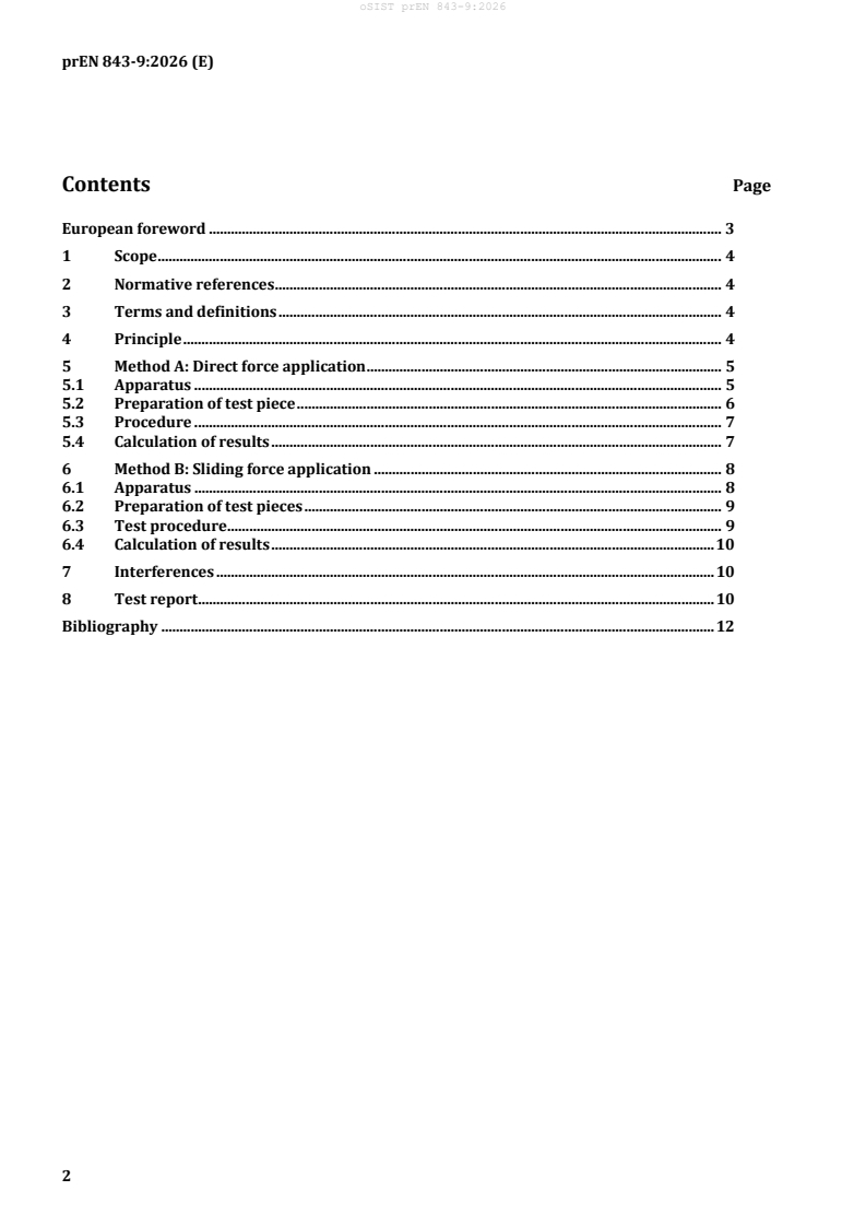
Contents Page
European foreword . 3
1 Scope . 4
2 Normative references . 4
3 Terms and definitions . 4
4 Principle . 4
5 Method A: Direct force application . 5
5.1 Apparatus . 5
5.2 Preparation of test piece . 6
5.3 Procedure . 7
5.4 Calculation of results . 7
6 Method B: Sliding force application . 8
6.1 Apparatus . 8
6.2 Preparation of test pieces . 9
6.3 Test procedure . 9
6.4 Calculation of results . 10
7 Interferences . 10
8 Test report . 10
Bibliography . 12
European foreword
This document (prEN 843-9:2026) has been prepared by Technical Committee CEN/TC 184 “Advanced
technical ceramics”, the secretariat of which is held by DIN.
This document is currently submitted to the CEN Enquiry.
This document will supersede CEN/TS 843-9:2010.
prEN 849-9:2026 includes the following significant technical changes with respect to
CEN/TS 843-9:2010:
a) conversion into a European Standard;
b) update of the normative references;
c) revised definitions of edge-chip and flake;
d) editorial revision.
A list of all parts in the EN 843 series, published under the general title Advanced technical ceramics —
Mechanical properties of monolithic ceramics at room temperature, can be found on the CEN website.
1 Scope
This document specifies two test methods for the determination of the resistance of the edges of brittle
ceramic materials to be damaged by chipping.
This document is applicable to homogeneous monolithic ceramics with flat surfaces and straight sharp
or chamfered edges.
2 Normative references
The following documents are referred to in the text in such a way that some or all of their content
constitutes requirements of this document. For dated references, only the edition cited applies. For
undated references, the latest edition of the referenced document (including any amendments) applies.
EN ISO 7500-1, Metallic materials — Calibration and verification of static uniaxial testing machines —
Part 1: Tension/compression testing machines — Calibration and verification of the force-measuring system
(ISO 7500-1)
EN ISO/IEC 17025, General requirements for the competence of testing and calibration laboratories
(ISO/IEC 17025)
3 Terms and definitions
For the purposes of this document, the following terms and definitions apply.
ISO and IEC maintain terminology databases for use in standardization at the following addresses:
— ISO Online browsing platform: available at https://www.iso.org/obp/
— IEC Electropedia: available at https://www.electropedia.org/
3.1
edge-chip
recessed defect at the edge of a component or test piece caused by localised stress or impact
3.2
flake
detached piece of material from the edge of a component or test piece
3.3
edge chipping
process of producing an edge-chip from the edge of a component or test piece by localised loading or
impact
3.4
edge chip resistance
edge toughness
measure of the resistance of the edge of a component or test piece to chipping determined by dividing
the force applied by the maximum thickness of the edge-chip or the distance of the centre of the applied
force from the edge at which it is formed
4 Principle
Localized loading near the edge of a ceramic component can lead to spalling of the edge, and hence to loss
of function of the component. The test methods in this document provide means of quantifying the
resistance of a ceramic product to edge damage, either by applying a monotonically increasing force to
an indenter positioned a fixed distance from the edge (Method A), or by applying a predetermined force
to an indenter positioned remotely from the edge and dragging it towards the edge (Method B). In the
case of method A, the force required to cause an edge-chip to form at a pre-determined position is
recorded while in the case of Method B, the distance from the edge at which the edge-chip is formed under
a pre-determined force is measured. In both cases (see Figure 1), the force applied, F, divided by the
distance from the edge at which the edge-chip is formed, d, commonly known as the ‘edge toughness’, is
then a measure of edge-chip resistance.
This test can also be used to determine the effectiveness of chamfers placed on edges. A chamfer prevents
direct loading near the edge. The size of the chamfer required for the component to withstand a given
near-edge loading can be determined by this test.
a) b)
Key
F indenter applying force normal to plane
d maximum edge-chip depth into bulk
w maximum edge-chip width on face
Figure 1 — Schematic of indentation near an edge using a hard indenter (a) cross-sectional view
of an edge-chip formed at an edge, and (b) edge-chip shape viewed from edge side
5 Method A: Direct force application
5.1 Apparatus
The force required shall be applied by any suitable mechanical testing machine which operates in a
constant displacement rate mode. The machine shall drive an indenter (5.1.3) into the surface of a
component or test piece at a pre-determined location near the edge until the edge-chip forms.
NOTE The mechanism of edge-chip formation is thought be the preferred extension of those radial cracks
emanating from the indentation which are roughly parallel with the edge. Owing to the lack of elastic constraint
near the edge, these propagate sideways and into the material to form a shell-shaped crack, which once past a
certain size becomes unstable and forms a detached flake.
5.1.1 Test machine. A mechanical testing machine shall be used, which is capable of applying a force
to the test jig at a constant displacement rate. The test machine shall be equipped for recording the load
applied to the test jig at any point in time, and preferably of capturing the peak force applied. The accuracy
of the test machine shall be in accordance with EN ISO 7500-1, Grade 1 (1 % of indicated load), and shall
be capable of recording to a sensitivity of better than 1 % of the maximum load employed.
5.1.2 Test piece holder. The test-piece shall be held in a clamping device which enables the test piece
or test item to be held in a fixed position in the testing machine (Figure 2). Preferably the clamping device
incorporates two orthogonal means of adjusting position so that the location of the indenter (5.1.3) can
be adjusted precisely, e.g. using an X-Y micrometer screw table which can be locked when indenting.
NOTE It is convenient to see the indentation position by sighting normal to the indentation surface using a
microscope or other suitable device, e.g. by moving the indenter out of the line of sight. Such an arrangement permits
the indenter to be positioned an exact distance from the edge of the test piece.
Key
1 load cell
2 indenter
3 test piece or test item
4 X-Y lockable table
Figure 2 — Schematic of indentation technique for Method A
5.1.3 Indenter. A sharp or a blunt diamond indenter shall be used for this test, as appropriate to
requirements.
It is recommended that for reliability, especially in high force tests, a Rockwell geometry diamond (see
EN ISO 14705) with a tip radius of 0,2 mm and manufactured from polycrystalline diamond is employed.
If a Vickers or Knoop diamond is used, ensure that the diagonal length of the indentation is consistently
aligned with the edge of the test piece.
5.2 Preparat
...